P5AB56Wireless Mouse
ARESON Technology Corp.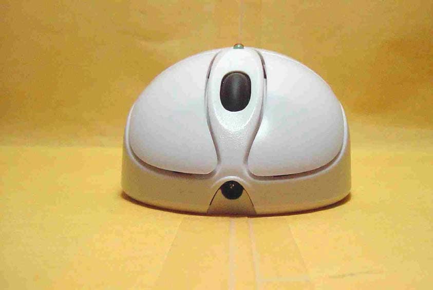
Click to zoom
Application Details
- Equipment Class
- DXX - Part 15 Low Power Communication Device Transmitter
- Date of Grant
- Nov 28, 2002
- Application Purpose
- Original Equipment
- Date of Application
- Nov 28, 2002
- Equipment Note
- Wireless Mouse
- Frequency Range
- 27.04500000 - 27.04500000
- Company
- ARESON Technology Corp.
- Country
- Taiwan
Documents & Files
Document Text
Text extracted from the exhibit documents filed with the FCC. Open a document above to read the original.
Users Manual
Information to User Notice 1 You are cautioned that changes or modifica tions not expressly approved by the part responsible for compliance could void the user’s authority to operate the equipment. Notice 2 This equipment has been tested and found to comply with the limits for a Class B digital device, pursuant to part 15 of the FCC rules. These limits are designed to provide reasonable protection against harmful interference in a residential installation. This equipment generates, us es and can radiate radio frequency energy and, if not installed and used in accordan ce with the instructi ons, may cause harmful interference to radio communications.
Block Diagram
X Y Z Axis Input RB LB Input MCU D+ , CLK D- , DATA RF MOUSE BLOCK DIAGRAM X’TAL 4MHz RF TX Module X’TAL 27.045MHz RF RX Module MCU X’TAL 26.590MHz
Cover Letter(s)
From: Eva Kao [[email protected]] Sent: Thursday, November 28, 2002 5:59 PM To: Mike Kuo Cc: Vincent Subject: Fw: ARESON Technology Corp., FCC ID:P5AB56, AN02T2404 Resend ----- Original Message ----- From: "Eva Kao" <[email protected]> To: "Mike Kuo" <[email protected]> Sent: Friday, November 22, 2002 7:11 PM Subject: Re: ARESON Technology Corp., FCC ID:P5AB56, AN02T2404 > Hi Mike, > > Answer #1: Please find the attached is revised test report. > > Answer #2: Please find the attachment are External and Internal photos to > added DC connector. > > Thanks a lot. > Eva > > > ----- Original Message ----- > From: "Mike Kuo" <[email protected]> > To: "Eva Kao (E-mail)" <[email protected]> > Sent: Friday, November 22, 2002 9:41 AM > Subject: FW: ARESON Technology Corp., FCC ID:P5AB56, AN02T2404 > > > > > > > > -----Original Message----- > > From: CERTADM > > Sent: Thursday, November 21, 2002 5:41 PM > > To: '[email protected]' > > Subject: ARESON Technology Corp., FCC ID:P5AB56, AN02T2404 > > > > > > Notice_content > > ------------- > > Question #1: Page 7 of test report listed the FCC ID number does not agree > > with filing. Please make necessary change. > > > > Question #2: the DC connector can not be located on the internal photos. > > Please provide additional photos to show where is DC connector on the Eut > to > > enable battery charge. > > > > Best Regards > > > > Mike Kuo > > The items indicated above must be submitted before processing can continue > > on the above referenced application. Failure to provide the requested > > information within 60 days of the original e-mail date may result in > > application dismissal and forfeiture of the filing fee. Also, please note > > that partial responses increase processing time and should not be > submitted. > > Any questions about the content of this correspondence should be directed > to > > the e-mail address listed below the name of the sender. >
External Photos
C&C Laboratory Co. Ltd. REPORT NO: 020069-RF-ID FCC ID: P5AB56 DATE: 10/18/2002 APPENDIX 2 EXTERNAL PHOTOGRAPHS OF EUT C&C Laboratory Co. Ltd. REPORT NO: 020069-RF-ID FCC ID: P5AB56 DATE: 10/18/2002 Front View of EUT Back View of EUT C&C Laboratory Co. Ltd. REPORT NO: 020069-RF-ID FCC ID: P5AB56 DATE: 10/18/2002 Top View of EUT
ID Label/Location Info
FCC ID LABEL FORMAT AND LOCATION Applicant: ARESON Technology Corp. FCC ID: P5AB56 FCC ID: P5AB56 This device complies with part 15 of the FCC Rules. Operation is subject to the following two conditions: (1) This device may not cause harmful interference, and (2) this device must accept any interference received, including interference that may cause undesired operation. FCC ID LABEL AREA
Internal Photos
C&C Laboratory Co. Ltd. REPORT NO: 020069-RF-ID FCC ID: P5AB56 DATE: 10/18/2002 APPENDIX 3 INTERNAL PHOTOGRAPHS OF EUT C&C Laboratory Co. Ltd. REPORT NO: 020069-RF-ID FCC ID: P5AB56 DATE: 10/18/2002 Internal of EUT – Open Internal of EUT – 1 C&C Laboratory Co. Ltd. REPORT NO: 020069-RF-ID FCC ID: P5AB56 DATE: 10/18/2002 Internal of EUT – 2 Internal of EUT – 3 C&C Laboratory Co. Ltd. REPORT NO: 020069-RF-ID FCC ID: P5AB56 DATE: 10/18/2002 Internal of EUT – 4 Internal of EUT – 5 C&C Laboratory Co. Ltd. REPORT NO: 020069-RF-ID FCC ID: P5AB56 DATE: 10/18/2002
Operational Description
B56/C03 system description.doc Mouse B56 transmitter 1. Scroll sensor will compare the image data , and send it with X-axis, Y-axis, Z-axis format to MCU. 2. MCU will scan x, y, z axis, encoder and ID/reset key. If any signal change come from above mention. It will turn convert the data package with checking the low battery status data, and prepare for modulate to the reference x’tal directly. 3. When MCU received the signal from x, y axis, encoder and ID/reset key. Firstly, MCU will turn on the RF power,( e.g.27.045MHz) 4. The reference x’tal will support the exact 3 rd tone of the exact frequency( e.g.27.045MHz) 5. Buffer amplifier is to change the impedance between oscillating circuit(high impedance) to low impedance. 6. (PA)Power amplifier is to support enough current to drive the antenna. 7. Matching circuit is to match the impedance between PA and antenna. C03 receiver 1. When the PC power on, the receiver will start the PnP process of USB. 2. MCU will turn on the RF power of RF. 3. When the RF signal comes(e.g. 27.045MHz for mouse),the signal will direct to the mixer. 4. The RF signal is pass through mixer. It means that the original signal (27.045MHz from mouse) will down convert to 455KHz from mouse. 5. U2 filter are perform a filtering function of 455KHz. 6. 455KHz resonator will perform the local oscillator (LO)function. 7. When the U2(455KHz) pass through discriminator, the demodulating signal will come out. We called it base band signal of mouse or keyboard. 8. AF AMP will work as a data slicer, it amplify the signal to square wave digital signal. 9. This digital signal will send to MCUs. MCUs will sample the signal to check it is valid or not. 10. If the signal it valid, MCUs will convert the signal to the USB interface to PC. No-matter is exact activity of mouse. 11. MCUs also scan the reset lock key to check user has to press this key or not.
Test Report
C&C Laboratory Co. Ltd. REPORT NO: 020069-RF-ID FCC ID: P5AB56 DATE: 10/18/2002 Page 1 of 29 Rev. 01 ELECTROMAGNETIC EMISSIONS COMPLIANCE REPORT INTENTIONAL RADIATOR CERTIFICATION TO FCC PART 15 SUBPART C REQUIREMENT OF Wireless mouse MODEL No.: B56 BRAND NAME: ARESON FCC ID: P5AB56 REPORT NO: 020069-RF-ID ISSUE DATE: Oct. 18, 2002 Prepared for ARESON Technology Corp. 12F, No. 111-6, Hsing-De Rd., San Chung, Taipei Hsien, Taiwan, R.O.C. Prepared by C&C LABORATORY, CO., LTD. #B1, 1 st Fl., Universal Center, No. 183, Sec. 1, Tatung Rd., Hsi Chih, Taipei Hsien, Taiwan, R.O.C. TEL: (02)8642-2071~3 FAX: (02)8642-2256 C&C Laboratory Co. Ltd. REPORT NO: 020069-RF-ID FCC ID: P5AB56 DATE: 10/18/2002 Page 2 Rev. 01 Table of Contents 1. GENERAL INFORMATION ............................................................................................... 3 1.1 P RODUCT D ESCRIPTION ........................................................................................................................ 3 1.2 R ELATED S UBMITTAL ( S ) / G RANT ( S )................................................................................................... 3 1.3 T EST M ETHODOLOGY ............................................................................................................................ 3 1.4 T EST F ACILITY ...................................................................................................................................... 3 1.5 S PECIAL A CCESSORIES .......................................................................................................................... 3 1.6 E QUIPMENT M ODIFICATIONS ................................................................................................................ 3 2. SYSTEM TEST CONFIGURATION .................................................................................. 4 2.1 EUT C ONFIGURATION ........................................................................................................................... 4 2.2 EUT E XERCISE ...................................................................................................................................... 4 2.3 T EST P ROCEDURE .................................................................................................................................. 4 2.4 L IMITATION ........................................................................................................................................... 5 2.5 C ONFIGURATION OF T ESTED S YSTEM ................................................................................................... 6 3. SUMMARY OF TEST RESULTS ....................................................................................... 8 4. DESCRIPTION OF TEST MODES .................................................................................... 8 5. CONDUCTED EMISSIONS TEST (NOT APPLICABLE IN THIS REPORT).......... 9 5.1 M EASUREMENT P ROCEDURE : ............................................................................................................... 9 5.2 T EST SET-UP (B LOCK D IAGRAM OF C ONFIGURATION ) ....................................................................... 9 5.3 MEASUREMENT EQUIPMENT USED: ...................................................................................................... 9 5.4 C ONDUCTED M EASUREMENT D ATA ................................................................................................... 10 6. RADIATED EMISSION TEST .......................................................................................... 12 6.1 M EASUREMENT P ROCEDURE ............................................................................................................... 12 6.2 TEST SET-UP (BLOCK DIAGRAM OF CONFIGURATION) ..................................................................... 13 6.3 M EASUREMENT E QUIPMENT U SED : .................................................................................................... 14 6.4 F IELD S TRENGTH C ALCULATION ........................................................................................................ 14 6.5 MEASUREMENT RESULT..................................................................................................................... 15 7. OCCUPIED BANDWIDTH................................................................................................ 19 7.1 M EASUREMENT P ROCEDURE ............................................................................................................... 19 7.2 T EST SET-UP (B LOCK D IAGRAM OF C ONFIGURATION ) ..................................................................... 19 7.3 MEASUREMENT EQUIPMENT USED: .................................................................................................... 19 7.4 M EASUREMENT R ESULTS :................................................................................................................... 19 C&C Laboratory Co. Ltd. REPORT NO: 020069-RF-ID FCC ID: P5AB56 DATE: 10/18/2002 Page 3 Rev. 01 1. GENERAL INFORMATION 1.1 Product Description The ARESON Technology Corp. . Model: B56 (referred to as the EUT in this report) The EUT is an short range, lower power, wireless mouse designed as an " Input Device. It is designed by way of utilizing the FSK modulation achieves the system operating. A major technical descriptions of EUT is described as following: A). Operation Frequency: 27.045 MHz, one channel. B). Modulation : Frequency Shifting Key (FSK) Modulation C). Antenna Designation: Non-User Replaceable (Fixed) D). Power Supply: 3 Vdc by AAA *2 battery. 1.2 Related Submittal(s) / Grant (s) This submittal(s) (test report) is intended for FCC ID : P5AB56 filing to comply with Section 15.227 of the FCC Part 15, Subpart C Rules. The composite system(receiver) is compliance with Subpart B is authorized under a DoC procedure. 1.3 Test Methodology Both conducted and radiated testing were performed according to the procedures in ANSI C…
Text truncated - open the document above for the full version.
Test Setup Photos
C&C Laboratory Co. Ltd. REPORT NO: 020069-RF-ID FCC ID: P5AB56 DATE: 10/18/2002 APPENDIX 1 PHOTOGRAPHS OF SET UP C&C Laboratory Co. Ltd. REPORT NO: 020069-RF-ID FCC ID: P5AB56 DATE: 10/18/2002 Conducted Emission Setup Photos C&C Laboratory Co. Ltd. REPORT NO: 020069-RF-ID FCC ID: P5AB56 DATE: 10/18/2002 Radiated Emission Setup Photos
Contact Information
Applicant
Jane Chang(Product Manager)
Test Firm
Compliance Certification Services Inc.Kurt Chen
Technical Specifications
| # | Rule Parts | Frequency Range | Power Output |
|---|---|---|---|
| 1 | 15C | 27.045 MHz - 27.045 MHz | - |
Other Applications from ARESON Technology Corp.

P5A-CB0033
Nov 22, 20202.4 GHz Wireless Trackball Mouse
Equipment Class
DXX - Part 15 Low Power Communication Device Transmitter
P5A-CL0033
Apr 13, 20152.4GHz Wireless Dongle
Equipment Class
DXX - Part 15 Low Power Communication Device Transmitter
P5A-CB0020
Apr 13, 20152.4GHz Wireless Mouse
Equipment Class
DXX - Part 15 Low Power Communication Device Transmitter
P5A-CB0019
Jul 24, 20142.4GHz Wireless Touch Pad
Equipment Class
DXX - Part 15 Low Power Communication Device Transmitter
P5A-CL0032
Jul 07, 20142.4GHz Wireless Receiver
Equipment Class
DXX - Part 15 Low Power Communication Device Transmitter