P5J-ONISHGSM 900/1800/1900 Phone with PDA
Danger, Inc.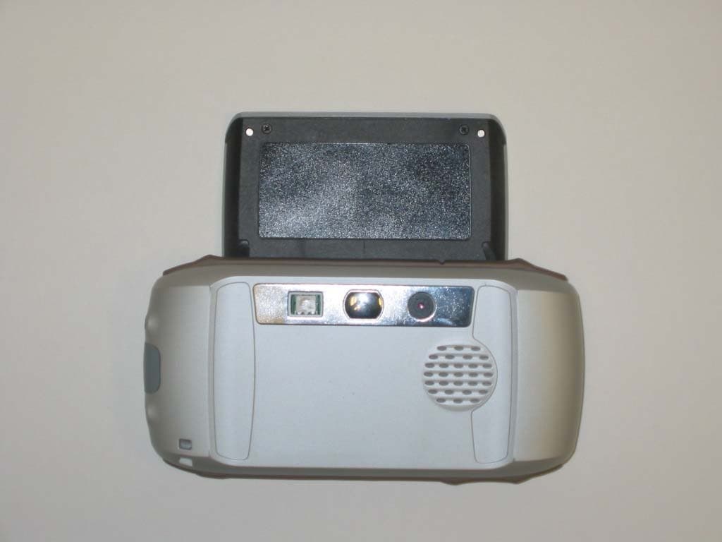
Click to zoom
Application Details
- Equipment Class
- PCE - PCS Licensed Transmitter held to ear
- Date of Grant
- Jun 21, 2004
- Application Purpose
- Original Equipment
- Date of Application
- Jun 21, 2004
- Equipment Note
- GSM 900/1800/1900 Phone with PDA
- Frequency Range
- 1850.20000000 - 1909.80000000
- Company
- Danger, Inc.
- Country
- United States
Documents & Files
Document Text
Text extracted from the exhibit documents filed with the FCC. Open a document above to read the original.
Users Manual
Sidekick II Reference Guide 27-2002-01 Rev. A - Release 2.0 - June 7, 2004 Copyright © 2004 Danger, Inc. All rights reserved. 2 Contents Contents Welcome! 6 I. Device Controls 8 Opening and Closing the Display 8 Phone Controls 9 Control Buttons 1 0 II. Registration 12 III. Device Basics 16 Battery Charger 16 USB Port 1 7 Wrist Strap Holder 1 7 The Jump Screen 1 8 Title Bar and Indicators 1 9 Menus 2 0 Device Settings 2 1 Sound and Display Controls 2 1 Backlighting 2 2 Key Guard Mode 2 2 Device Privacy Code 2 3 Customization 24 Default Locale Setting 2 5 Typing and Editing Text 2 5 Navigating in Text Boxes 2 5 Deleting Text 2 6 Entering Special Unicode Characters 2 6 Cut, Copy, Paste 2 7 AutoText 2 7 IV. The Desktop Interface 28 V. Using the Applications 30 Phone Make a Phone Call 30 Answer a Phone Call 3 1 Add a Number to Your Speed Dial List 3 1 Change Your Phone Ringtone 3 2 Check Your Voice Mail 3 2 Import Contacts from Your SIM Card 3 3 Phone Messages Send a Text Message 33 Contents 3 Web Browser Browse the Web 34 Bookmark a Web Page 3 4 Email Send an Email Message 35 Fetch Email from External Accounts 3 5 Fetch Email Using Your Device’s Web Browser 3 9 Attach a Photo to an Email Message 3 9 Address Book Add a Contact to the Address Book 40 Import Address Book Contacts 4 1 Calendar Add an Event to Calendar 42 Notes Create a Note 43 To Do Add a Task 43 Camera Take a Photo 44 Send a Photo by Email 4 4 4 Contents Download Fun ™ Catalog Purchase Items 45 Manage Your Purchases 4 6 Instant Messaging Sign On 47 Send an Instant Message 4 7 Switch Between IM Conversations 4 8 VI. Keyboard Shortcuts 49 VII. Troubleshooting 50 VIII. Handling and Safety Precautions 54 Battery Handling 54 Device Handling and Use 5 5 Battery Charger Handling 5 6 Radio Frequency Exposure 5 7 Regulatory Compliance Information 5 8 IX. Legal Information 60 Contents 5 ���� Welcome! Thank you for buying a Sidekick II. Your Sidekick II will change the way you communicate, get organized, and stay connected. Your Sidekick II connects seamlessly to wireless networks, which gives you the ability to browse the Internet, exchange instant messages, and send and receive email with image attachments. Other features include a full-featured phone, personal information management (PIM) applications, access to a personal Web portal, a catalog for downloading ringtones and applications to your device, and a built-in camera. For the latest instructions on all the Sidekick II applications, open the online Owner’s Manual from the Help link on the Desktop Interface. 6 Welcome! Welcome! 7 Here’s what you’ll find in the box: Sidekick II Device SIM Card Battery Charger Hands-Free Headset Carrying Case Start Guide Reference Guide T-Mobile Welcome Guide If any of these items are missing, please contact T-Mobile’s Customer Care department. Now, let’s get started! Warning Device Controls Opening and Closing the Display To open the display, press your left thumb on the lower-left corner of the display and gently push in a clockwise direction. The display will spring smoothly into the open position. Alternatively, use your right index finger to push down gently on the upper- right corner of the display. The screen will spring into the open position. The normal operating position of the device is horizontal, with the wheel on the right side, as shown above. To close the display, reverse the motion to pivot the display counter-clockwise and snap it into the closed position. Do not open or close the display in the wrong direction or you risk damaging your device. Stop if you feel any resistance; the display should spring smoothly into position. Protect the display from scratches by always using the carrying case to transport your device. I. 8 Device Controls Phone Controls VOLUME BUTTONS + - DIAL PAD SEND CALL END CALL SPEAKERPHONE ON / OFF MUTE ON / OFF DIAL PAD Use the dial pad within the keyboard to dial a number using just your right hand. END CALL and SEND CALL buttons While on a phone call, press to end a phone call or clear the screen of a number you’ve typed. Press to place a call to the phone number you’ve typed or highlighted in a list. Pressing with no number typed launches a list of recently-dialed numbers. SPEAKER When using the phone as a handset, position the speaker to your ear. MICROPHONE While on the Phone speak into the microphone. VOLUME buttons The volume buttons are under the JUMP button. While on a phone call, press + to increase and - to decrease volume. Use the shoulder buttons to turn Mute or Speakerphone on and off. Device Controls 9 SPEAKER MICROPHONE VOLUME BUTTONS Control Buttons MENU JUMP WHEEL CANCEL DONE WHEEL Pressing the wheel selects a highlighted item or opens a pop-up menu. Rotate the wheel up/down to reverse/advance the current selection through the “selectable” items on a screen, or to scroll up/down a Web page. Use the SEND CALL and END CALL buttons while using the phone. When not on the phone, these buttons will page up and page down. DONE button Pressing DONE takes you back to the screen you were previously viewing, until you reach the Jump screen. On a screen or in a dialog box, press DONE to save your changes and dismiss the screen or dialog box. If a menu is open, press DONE to close it. CANCEL button Pressing CANCEL dismisses any changes you have made to a screen or dialog box. MENU button Pressing MENU opens a menu of actions you can take on the current screen. If you press MENU and nothing opens, this means there are no menu actions available for the current screen. JUMP button Pressing JUMP takes you back to the Jump screen, your starting point for launching all the device applications. 10 Device Controls RIGHT SHOULDER BUTTON LEFT SHOULDER BUTTON POWER BUTTON VOLUME BUTTONS DIRECTIONAL PAD + - DIRECTIONAL PAD (D-Pad) Press up/down/left/right to scroll or move within text fields, and navigate in games. The D-Pad “rocks” into four different directions or positions. LEFT AND RIGHT SHOULDER buttons The f…
Text truncated - open the document above for the full version.
External Photos
External photos PV-100 EUT – Front view with Display closed External photos PV-100 EUT – Front view with Display open External photos PV-100 EUT – Rear view with Display closed External photos PV-100 EUT – Rear view with Display open
ID Label/Location Info
Danger Hiptop HT-G02003 Back side of Hiptop HT-G02003 Fig. 1 Location of Compliance Label on back side of screen. Fig 2. M1 Compliance Label
Internal Photos
Internal photos PV-100 PCB – Top view Internal photos PV-100 PCB – Bottom view Antenna
RF Exposure Info
SAR Test Report No.: SAR_631_2004_FCC_1900 Date of Report: 4/7/2004 Appendix A Plots Page 1 of 16 Date / Time: 3/10/2004 3:13:21 PM Position: left touch Filename: *.txt Phantom: HeadFT26.csv Device Tested: Danger Head Rotation: 0 Antenna: integral Test Frequency: 1880 Shape File: danger_m1.csv Power Level: max Probe: 0106 Cal File: 106_1900_HEAD_GSM X Y Z Air 415 805 371 DCP 9.4 2.7 7.8 Cal Factors: Lin 0.423 0.423 0.423 Amp Gain: 32 Averaging: 6 Batteries Replaced: 02/11/04 Liquid: 1900 Type: Head Conductivity: 1.424 Relative Permittivity: 39.36 Liquid Temp (deg C): 22.0 Ambient Temp (deg C): 22.0 Ambient RH (%): 50 Density (kg/m3): 1000 Software Version: 0.420 ZOOM SCAN RESULTS: Start Scan End Scan Spot SAR (W/kg): 0.181 0.182 Change during Scan (%) 0.43 Max E-field (V/m): 19.49 1g 10g Max SAR (W/kg) 0.482 0.319 X Y Z Location of Max (mm): 78.7 -36.0 -126.6 AREA SCAN: Min Max Steps Y 20.0 -80.0 10.0 Scan Extent: Z -200.0 -100.0 10.0 SAR Test Report No.: SAR_631_2004_FCC_1900 Date of Report: 4/7/2004 Appendix A Plots Page 2 of 16 Date / Time: 3/10/2004 3:53:49 PM Position: left tilt Filename: *.txt Phantom: HeadFT26.csv Device Tested: Danger Head Rotation: 0 Antenna: integral Test Frequency: 1880 Shape File: danger_m1.csv Power Level: max Probe: 0106 Cal File: 106_1900_HEAD_GSM X Y Z Air 415 805 371 DCP 9.4 2.7 7.8 Cal Factors: Lin 0.423 0.423 0.423 Amp Gain: 32 Averaging: 6 Batteries Replaced: 02/11/04 Liquid: 1900 Type: Head Conductivity: 1.424 Relative Permittivity: 39.36 Liquid Temp (deg C): 22.0 Ambient Temp (deg C): 22.0 Ambient RH (%): 50 Density (kg/m3): 1000 Software Version: 0.420 ZOOM SCAN RESULTS: Start Scan End Scan Spot SAR (W/kg): 0.186 0.186 Change during Scan (%) 0.03 Max E-field (V/m): 20.41 1g 10g Max SAR (W/kg) 0.537 0.335 X Y Z Location of Max (mm): 78.8 -31.0 -124.9 AREA SCAN: Min Max Steps Y 20.0 -80.0 10.0 Scan Extent: Z -200.0 -100.0 10.0 SAR Test Report No.: SAR_631_2004_FCC_1900 Date of Report: 4/7/2004 Appendix A Plots Page 3 of 16 Date / Time: 3/10/2004 2:16:25 PM Position: Right touch Filename: *.txt Phantom: HeadFT26.csv Device Tested: Danger Head Rotation: 180 Antenna: integral Test Frequency: 1880 Shape File: danger_m1.csv Power Level: max Probe: 0106 Cal File: 106_1900_HEAD_GSM X Y Z Air 415 805 371 DCP 9.4 2.7 7.8 Cal Factors: Lin 0.423 0.423 0.423 Amp Gain: 32 Averaging: 6 Batteries Replaced: 02/11/04 Liquid: 1900 Type: Head Conductivity: 1.424 Relative Permittivity: 39.36 Liquid Temp (deg C): 22.0 Ambient Temp (deg C): 22.0 Ambient RH (%): 50 Density (kg/m3): 1000 Software Version: 0.420 ZOOM SCAN RESULTS: Start Scan End Scan Spot SAR (W/kg): 0.217 0.218 Change during Scan (%) 0.43 Max E-field (V/m): 20.94 1g 10g Max SAR (W/kg) 0.533 0.339 X Y Z Location of Max (mm): 77.5 10.0 -125.0 AREA SCAN: Min Max Steps Y -20.0 80.0 10.0 Scan Extent: Z -200.0 -100.0 10.0 SAR Test Report No.: SAR_631_2004_FCC_1900 Date of Report: 4/7/2004 Appendix A Plots Page 4 of 16 Date / Time: 3/10/2004 2:47:02 PM Position: Right tilt Filename: *.txt Phantom: HeadFT26.csv Device Tested: Danger Head Rotation: 180 Antenna: integral Test Frequency: 1880 Shape File: danger_m1.csv Power Level: max Probe: 0106 Cal File: 106_1900_HEAD_GSM X Y Z Air 415 805 371 DCP 9.4 2.7 7.8 Cal Factors: Lin 0.423 0.423 0.423 Amp Gain: 32 Averaging: 6 Batteries Replaced: 02/11/04 Liquid: 1900 Type: Head Conductivity: 1.424 Relative Permittivity: 39.36 Liquid Temp (deg C): 22.0 Ambient Temp (deg C): 22.0 Ambient RH (%): 50 Density (kg/m3): 1000 Software Version: 0.420 ZOOM SCAN RESULTS: Start Scan End Scan Spot SAR (W/kg): 0.169 0.169 Change during Scan (%) 0.13 Max E-field (V/m): 19.59 1g 10g Max SAR (W/kg) 0.434 0.265 X Y Z Location of Max (mm): 74.3 -4.0 -118.9 AREA SCAN: Min Max Steps Y -20.0 80.0 10.0 Scan Extent: Z -200.0 -100.0 10.0 SAR Test Report No.: SAR_631_2004_FCC_1900 Date of Report: 4/7/2004 Appendix A Plots Page 5 of 16 Date / Time: 3/10/2004 4:18:32 PM Position: left tilt Filename: *.txt Phantom: HeadFT26.csv Device Tested: Danger Head Rotation: 0 Antenna: integral Test Frequency: 1850.2 Shape File: danger_m1.csv Power Level: max Probe: 0106 Cal File: 106_1900_HEAD_GSM X Y Z Air 415 805 371 DCP 9.4 2.7 7.8 Cal Factors: Lin 0.423 0.423 0.423 Amp Gain: 32 Averaging: 6 Batteries Replaced: 02/11/04 Liquid: 1900 Type: Head Conductivity: 1.403 Relative Permittivity: 39.66 Liquid Temp (deg C): 22.0 Ambient Temp (deg C): 22.0 Ambient RH (%): 50 Density (kg/m3): 1000 Software Version: 0.420 ZOOM SCAN RESULTS: Start Scan End Scan Spot SAR (W/kg): 0.160 0.160 Change during Scan (%) -0.02 Max E-field (V/m): 18.84 1g 10g Max SAR (W/kg) 0.452 0.283 X Y Z Location of Max (mm): 78.8 -31.0 -123.9 AREA SCAN: Min Max Steps Y 20.0 -80.0 10.0 Scan Extent: Z -200.0 -100.0 10.0 SAR Test Report No.: SAR_631_2004_FCC_1900 Date of Report: 4/7/2004 Appendix A Plots Page 6 of 16 Date / Time: 3/10/2004 4:58:39 PM Position: Left tilt Filename: *.txt Phantom: HeadFT26.csv Device Tested: Danger Head Rotation: 0 Antenna: integral Test Frequency: 1909.8 Shape File: danger_m1.csv Power Level: max Probe: 0106 Cal File: 106_1900_HEAD_GSM X Y Z Air 415 805 371 DCP 9.4 2.7 7.8 Cal Factors: Lin 0.423 0.423 0.423 Amp Gain: 32 Averaging: 6 Batteries Replaced: 02/11/04 Liquid: 1900 Type: Head Conductivity: 1.45 Relative Permittivity: 39.12 Liquid Temp (deg C): 22.0 Ambient Temp (deg C): 22.0 Ambient RH (%): 50 Density (kg/m3): 1000 Software Version: 0.420 ZOOM SCAN RESULTS: Start Scan End Scan Spot SAR (W/kg): 0.197 0.191 Change during Scan (%) -3.23 Max E-field (V/m): 19.81 1g 10g Max SAR (W/kg) 0.492 0.326 X Y Z Location of Max (mm): 78.4 -41.0 -126.8 AREA SCAN: Min Max Steps Y -80.0 20.0 10.0 Scan Extent: Z -200.0 -100.0 10.0 SAR Test Report No.: SAR_631_2004_FCC_1900 Date of Report: 4/7/2004 Appendix A Plots Page 7 of 16 Date / Time: 3/16/2004 8:55:47 AM Position: In pouch Filename: *.txt Phantom: HeadBox_new_spout.csv Device Tested: Danger Head Rotation: 0 Antenna: integral Test Frequency: 1880 Shape File: danger_m1.csv…
Text truncated - open the document above for the full version.
RF Exposure Info
SAR Test Report No.: SAR_631_2004_FCC_1900 Date of Report: 4/7/2004 Appendix C Page 1 of 36 1 Tissue Parameters 1900MHz Head liquid: Recipe: The following recipe is provided in percentage by weight. 54.9% distilled water 44.92% DGBE 0.18% salt 0.1% bactericide Di-electric constants measured on 3/10/2004, 03/16/2004 and 04/02/2004. SAR measurements were made within 24 hours of the measurement of liquid parameters. 3/10/2004 Freq. Rel. Condy (MHz) Perm. (S/m) 1850.2 39.66 1.403 1880 39.36 1.424 1900 39.29 1.437 1909.8 39.12 1.45 03/16/2004 Freq. Rel. Condy (MHz) Perm. (S/m) 1900 39.27 1.441 4/2/2004 Freq. Rel. Condy (MHz) Perm. (S/m) 1900 39.38 1.435 SAR Test Report No.: SAR_631_2004_FCC_1900 Date of Report: 4/7/2004 Appendix C Page 2 of 36 2 1900MHz Body Liquid: Recipe: The following recipe is provided in percentage by weight. 69.17% distilled water 30.29% DGBE 0.44% salt 0.1% bactericide Di-electric constants measured on 03/16/2004 and 04/02/2004. SAR measurements were made within 24 hours of the measurement of liquid parameters. 3/16/2004 Freq. Rel. Condy (MHz) Perm. (S/m) 1850.2 53.11 1.512 1880 52.96 1.560 1909.8 52.53 1.578 4/2/2004 Freq. Rel. Condy (MHz) Perm. (S/m) 1850.2 53.16 1.509 1880 53.01 1.561 1909.8 52.55 1.577 Environment: Temperature: 20.1 °C – 23.9°C Humidity: 45% _ 55 % SAR Test Report No.: SAR_631_2004_FCC_1900 Date of Report: 4/7/2004 Appendix C Page 3 of 36 3 Test Equipment Instrument description Supplier / Manufacturer Model Serial No. Calibration (date) Calibration Due (date) Bench top Robot Mitsubishi supplied by IndexSAR RV-E2 EA1030108 N/A N/A SAM Phantom Upright shell phantom made by Antennessa digitized and mounted by IndexSAR SAM 03FT26 04/03 N/A Flat Phantom IndexSAR HeadBox_Spout N/A N/A N/A Software IndexSAR SARA2 v0.420 N/A N/A N/A 1900MHz Head Tissue Simulant Cetecom Inc. 1900 Head N/A 3/10/04, 3/16/04 & 4/2/04 N/A 1900 MHz Body Tissue Simulant Cetecom Inc. 1900 Body N/A 3/16/04 & 4/2/04 N/A 1900 MHz Dipole IndexSAR – IEEE 1528 design IXD-190 190-0016 07/20/2003 07/20/2004 Netwok Analyzer Agilent 8753ES US39172511 04/22/2003 04/22/2004 Signal generator Rohde and Schwartz SMP02 830228/009 05/10/2003 05/10/2004 Directional coupler Werlatone C6529 11249 N/A N/A RF Amplifier Vectawave VTL5400 N/A N/A N/A Power Meter HP EPM-442A GB37170232 8/19/2003 8/19/2004 Power Sensor HP 8481A 1926A20587 8/19/2003 8/19/2004 SAR Probe IndexSAR IXP-050 S/N 0106 7/15/2003 7/15/2004 Probe amplifier IndexSAR IXA-010 S/N 043 N/A N/A Thermometer Control Company 4039 20410549 11/20/2001 11/20/2004 Dielectric Measurement Kit IndexSAR Di-Line N/A N/A N/A Test Equipment Model Serial SAR Test Report No.: SAR_631_2004_FCC_1900 Date of Report: 4/7/2004 Appendix C Page 4 of 36 4 Equipment Calibration/Performance Documents: Validation Dipoles Performance Measurements: Pages 5 to 9. Immersible SAR probe Calibration Report: Pages 10 to 36 Please Note: (The following pages of Appendix C show calibration documents. These calibration documents are inserted into this appendix. The header information with page numbering scheme is a part of this report and is included on all pages of the report and appendixes. This header is used to track all of the contents of this report.) SAR Test Report No.: SAR_631_2004_FCC_1900 Date of Report: 4/7/2004 Appendix C Page 5 of 36 5 Report No. SN0016_1900 30 th July 2002 INDEXSAR 1900MHz validation Dipole Type IXD-190 S/N 0016 Performance measurements MI Manning Indexsar, Oakfield House, Cudworth Lane, Newdigate, Surrey RH5 5DR. UK. Tel: +44 (0) 1306 631233 Fax: +44 (0) 1306 631834 e-mail: [email protected] 1. Measurement Conditions SAR Test Report No.: SAR_631_2004_FCC_1900 Date of Report: 4/7/2004 Appendix C Page 6 of 36 6 Measurements were performed using a box-shaped phantom made of PMMA with dimensions designed to meet the accuracy criteria for reasonably-sized phantoms that do not have liquid capacities substantially in excess of the volume of liquid required to fill the Indexsar upright SAM phantoms used for SAR testing of handsets against the ear. An HP 8753B vector network analyser was used for the return loss measurements. The dipole was placed in a special holder made of low-permittivity, low-loss materials. This holder enables the dipole to be positioned accurately in the centre of the base of the Indexsar box-phantom used for flat-surface testing and validation checks. The validation dipoles are supplied with special spacers made from a low-permittivity, low-loss foam material. These spacers are fitted to the dipole arms to ensure that, when the dipole is offered up to the phantom surface, the spacing between the dipole and the liquid surface is accurately aligned according to the guidance in the relevant standards documentation. The spacers are rectangular with a central hole equal to the dipole arm diameter and dimensioned so that the longer side can be used to ensure a spacing of 15mm from the liquid in the phantom (for tests at 900MHz and below) and the shorter side can be used for tests at 1800MHz and above to ensure a spacing of 10mm from the liquid in the phantom. The spacers are made on a CNC milling machine with an accuracy of 1/40 th mm but they may suffer wear and tear and need to be replaced periodically. The material used is Rohacell, which has a relative permittivity of approx. 1.05 and a negligible loss tangent. The apparatus supplied by Indexsar for dipole validation tests thus includes: Balanced dipoles for each frequency required are dimensioned according to the guidelines given in IEEE 1528 [1]. The dipoles are made from semi-rigid 50 Ohm co-ax, which is joined by soldering and is gold-plated subsequently. The constructed dipoles are easily deformed, if mis-handled, and periodic checks need to be made of their symmetry. Rohacell foam spacers designed for presenting the dipoles to 2mm thick PMMA box phantoms. These components also suffer wear and tear and should be replaced when the central hole is a loose-fit on the dipole a…
Text truncated - open the document above for the full version.
RF Exposure Info
Accredited according to ISO/IEC 17025 by: TTI-P-G 81/94-A0 CETECOM Inc. 411 Dixon Landing Road Milpitas, CA 95035 U.S.A. Phone: + 1 (408) 586 6200 Fax: + 1 (408) 586 6299 E-mail: [email protected] http://www.cetecom.com CETECOM Inc. is a Delaware Corporation with Corporation number: 2113686 Board of Directors: Dr. Harald Ansorge, Dr. Klaus Matkey, Hans Peter May V.2.16M-2002-03-12 x:\emc\projects_emc\danger\631-2004_pv-100\sar\report\sar_631_2004_fcc_1900.doc © Copyright by CETECOM SAR Test Report No. SAR_631_2004_FCC_1900 for the Danger, Inc. GSM /GPRS Tri- band (900/1800/1900 MHz) cell phone and data communication pocket device Model Number: PV-100 FCC ID: PJ5-ONISH Date of Report: 04/07/2004 Date of issue: 04/07/2004 Report Copy No.: 01 SAR Test Report No. SAR_631_2004_FCC_1900 Date of Report: 04/07/2004 Page 2 of 29 This report shall not be reproduced except in full without the written approval of: CETECOM Inc. SAR 411 Dixon Landing Road Milpitas, CA 95035 U.S.A. Contents 1. ASSESSMENT ...................................................................................................................4 2. ADMINISTRATIVE DATA...................................................................................................5 2.1. Identification of the Testing Laboratory Issuing the SAR Assessment Report ...............5 2.2. Identification of the Client...........................................................................................5 2.3. Identification of the Manufacturer...............................................................................5 3. EQUIPMENT UNDER INVESTIGATION (EUI)...................................................................6 3.1. Identification of the Equipment under Investigation ...................................................6 3.2. Front View of the Equipment under Investigation ......................................................7 4. SUBJECT OF INVESTIGATION ........................................................................................8 4.1. The IEEE Standard C95.1 and the FCC Exposure Criteria .......................................8 4.2. Distinction Between Exposed Population, Duration of Exposure and Frequencies...8 4.3. Distinction between Maximum Permissible Exposure and SAR Limits......................9 4.4. SAR Limit ...................................................................................................................9 5. THE FCC MEASUREMENT PROCEDURE .....................................................................10 5.1. General Requirements.............................................................................................10 5.2. Device Operating Next to a Person’s Ear ................................................................10 5.3. Test positions of device relative to head..................................................................11 5.4. Test to be Performed ...............................................................................................14 5.5. Body-worn and Other Configurations.......................................................................14 5.6. Procedure for assessing the peak spatial-average SAR .........................................15 5.7. Determination of the largest peak spatial-average SAR ..........................................17 6. THE MEASUREMENT SYSTEM ......................................................................................18 6.1. Robot system specification ......................................................................................18 6.2. Probe and amplifier specification .............................................................................19 6.3. Phantoms.................................................................................................................19 6.4. SAR measurement procedure .................................................................................20 6.5. SARA2 Interpolation and Extrapolation schemes ....................................................20 SAR Test Report No. SAR_631_2004_FCC_1900 Date of Report: 04/07/2004 Page 3 of 29 This report shall not be reproduced except in full without the written approval of: CETECOM Inc. SAR 411 Dixon Landing Road Milpitas, CA 95035 U.S.A. 6.6. Interpolation of 2D area scan...................................................................................21 6.7. Extrapolation of 3D scan..........................................................................................21 6.8. Interpolation of 3D scan and volume averaging.......................................................21 7. UNCERTAINTY ASSESSMENT.......................................................................................23 7.1. Table of Measurement Uncertainty Values of SAR Evaluations..............................24 7.2. Table of Measurement Uncertainty Values for SAR System Verification ................25 8. TEST RESULTS SUMMARY............................................................................................26 8.1. Description of EUT test positions and operation modes ..........................................26 8.2. Conducted Output Power.........................................................................................26 8.3. Head SAR results for GSM 1900MHz band for Hiptop v2 also “Sidekick“...............27 8.4. Body SAR results for GSM 1900MHz band for Hiptop v2 also “Sidekick“ in pouch version 1 ..................................................................................................................27 8.5. Body SAR results for GSM 1900MHz band for Hiptop v2 also “Sidekick“ in pouch version 2 ..................................................................................................................27 8.6. [Validation Check Results ........................................................................................28 9. REFERENCES............................................................…
Text truncated - open the document above for the full version.
Test Report
Master: ktldPT24sub Date: April 19, 1999 Nemko Test Report: 3L0345RUS1REV2 Applicant: Enfora Inc. 661 E/ 18 th Street Plano, Texas 75074 Equipment Under Test: Aspen – GSM/GPRS Wireless Modem (E.U.T.) GSM0107 In Accordance With: FCC Parts 24, Subpart E Broadband PCS Subscriber Station Tested By: Nemko Dallas Inc. 802 N. Kealy Lewisville, TX 75057-3136 Authorized By: Tom Tidwell, Frontline Manager Date: 28Apr04 Total Number of Pages: 37 Nemko Dallas FCC PARTS 2 and 24 GSM/GPRS Wireless Modem EQUIPMENT: GSM0107 Report No.: 3L0345RUS1 Page 2 of 39 Table of Contents Section 1. Summary of Test Results...............................................................................3 Section 2. General Equipment Specification................................................................5 Section 3. RF Power Output..............................................................................................7 Section 4. Occupied Bandwidth......................................................................................8 Section 5. Spurious Emissions at Antenna Terminals.............................................12 Section 6. Field Strength of Spurious..........................................................................23 Section 7. Frequency Stability........................................................................................26 Section 8. Test Equipment List......................................................................................27 ANNEX A - TEST METHODOLOGIES.................................................................................28 ANNEX B - TEST DIAGRAMS...............................................................................................34 Nemko Dallas FCC PARTS 2 and 24 GSM/GPRS Wireless Modem EQUIPMENT: GSM0107 Report No.: 3L0345RUS1 Page 3 of 39 Section 1. Summary of Test Results Manufacturer: Enfora Inc. Model No.: GSM0107 Serial No.: 28 General: All measurements are traceable to national standards. These tests were conducted on a sample of the equipment for the purpose of demonstrating compliance with FCC Part 24, Subpart E. New Submission Production Unit Class II Permissive Change Pre-Production Unit THIS TEST REPORT RELATES ONLY TO THE ITEM(S) TESTED. THE FOLLOWING DEVIATIONS FROM, ADDITIONS TO, OR EXCLUSIONS FROM THE TEST SPECIFICATIONS HAVE BEEN MADE. See “ Summary of Test Data”. TESTED BY: ____Eldon Berry______ DATE: _26 Aug., 2003_ Nemko Dallas Inc. authorizes the above named company to reproduce this report provided it is reproduced in its entirety and for use by the company’s employees only. Any use which a third party makes of this report, or any reliance on or decisions to be made based on it, are the responsibility of such third parties. Nemko Dallas Inc. accepts no responsibility for damages, if any, suffered by any third party as a result of decisions made or actions based on this report. This report applies only to the items tested. Nemko Dallas FCC PARTS 2 and 24 GSM/GPRS Wireless Modem EQUIPMENT: GSM0107 Report No.: 3L0345RUS1 Page 4 of 39 Summary Of Test Data NAME OF TEST PARA. NO. SPEC. RESULT RF Power Output 24.232 2W eirp Complies Occupied Bandwidth (TDMA) 24.238 Not Specified Complies Spurious Emissions at Antenna Terminals 24.238(a) -13 dBm Complies Field Strength of Spurious Emissions 24.238(a) -13 dBm E.I.R.P. Complies Frequency Stability 24.235 +/- 0.05 ppm Complies Footnotes: Nemko Dallas FCC PARTS 2 and 24 GSM/GPRS Wireless Modem EQUIPMENT: GSM0107 Report No.: 3L0345RUS1 Page 5 of 39 Section 2. General Equipment Specification Supply Voltage Input: 3.3 - 5 Vdc Frequency Bands: Block A 1850 – 1865 MHz Block D 1865 – 1870 MHz Block B 1870 – 1885 MHz Block E 1885 – 1890 MHz Block F : 1890 – 1895 MHz Block C 1895 – 1910 MHz GPRS 292K6G7W See page 9 for 20dB BW Type of Modulation and Designator: Output Impedance: 50 ohms RF Output (Rated): 1 Watt Nemko Dallas FCC PARTS 2 and 24 GSM/GPRS Wireless Modem EQUIPMENT: GSM0107 Report No.: 3L0345RUS1 Page 6 of 39 System Description This device is a wireless GSM/GPRS wireless modem that operates in the PCS band. System Diagram Nemko Dallas FCC PARTS 2 and 24 GSM/GPRS Wireless Modem EQUIPMENT: GSM0107 Report No.: 3L0345RUS1 Page 7 of 39 Section 3. RF Power Output NAME OF TEST: RF Power Output PARA. NO.: 24.232(b) TESTED BY: Eldon Berry DATE: 22Aug03 Test Results: Complies. Measurement Data: RF Power Output (Conducted) Job No.:3L0345RDate:8/22/2003 Specification:CFR 47, Part 24Temperature(°C):21 Tested By:Eldon BerryHumidity(%)50 E.U.T.:GSM0107 Configuration:EUT on test fixture. Detector:Average Test Equipment Used: Power Meter:E4418BDirectional Coupler: Power Sensor:E9304ACable #1:1083 Load:Cable #2: Spectrum Analyzer:NACable #3: Attenuator #11604Cable #4: Attenuator #2:Cable #5: Attenuator #3:Cable #6: Attenuator #4:Power Splitter: Measurement Uncertainty:+/- .7 dB FrequencyModulationOutput PowerOutput MHzType(dBm)Power (mW) 1850.2512GPRS29.8954.99 1880.2662GPRS29.7933.25 1909.8810GPRS28.8758.58 Power meter set for 12.5 % duty cycle. Cable and attenuator verified with generator # 1053 Channel Nemko Dallas FCC PARTS 2 and 24 GSM/GPRS Wireless Modem EQUIPMENT: GSM0107 Report No.: 3L0345RUS1 Page 8 of 39 Section 4. Occupied Bandwidth NAME OF TEST: Occupied Bandwidth PARA. NO.: 24.238 TESTED BY: Dustin Oaks DATE: April 26, 2004 Test Results: Complies. Test Data: See attached plots. Test Equipment Used: 1036, 1973, 1604 Nemko Dallas FCC PARTS 2 and 24 GSM/GPRS Wireless Modem EQUIPMENT: GSM0107 Report No.: 3L0345RUS1 Page 9 of 39 …
Text truncated - open the document above for the full version.
Contact Information
Applicant
Gavin O'Duffy(Manager, Compliance Engineering)
Test Firm
Cetecom ICT Services GmbHRalf Hoehn
Technical Specifications
| # | Rule Parts | Frequency Range | Power Output | Emission | Tolerance |
|---|---|---|---|---|---|
| 1 | 24E | 1.85 GHz - 1.91 GHz | 1.045 W | 300KGXW | 0.0090000000 ppm |
Other Applications from Danger, Inc.
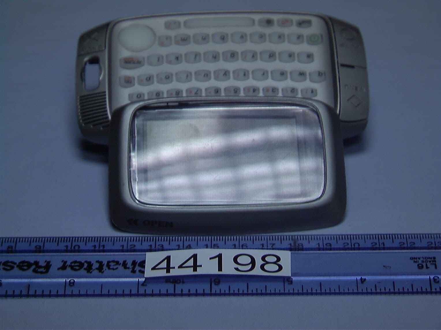
P5J-SKCA
Apr 29, 2003PCS handset with wireless data access and PDA
Equipment Class
PCE - PCS Licensed Transmitter held to ear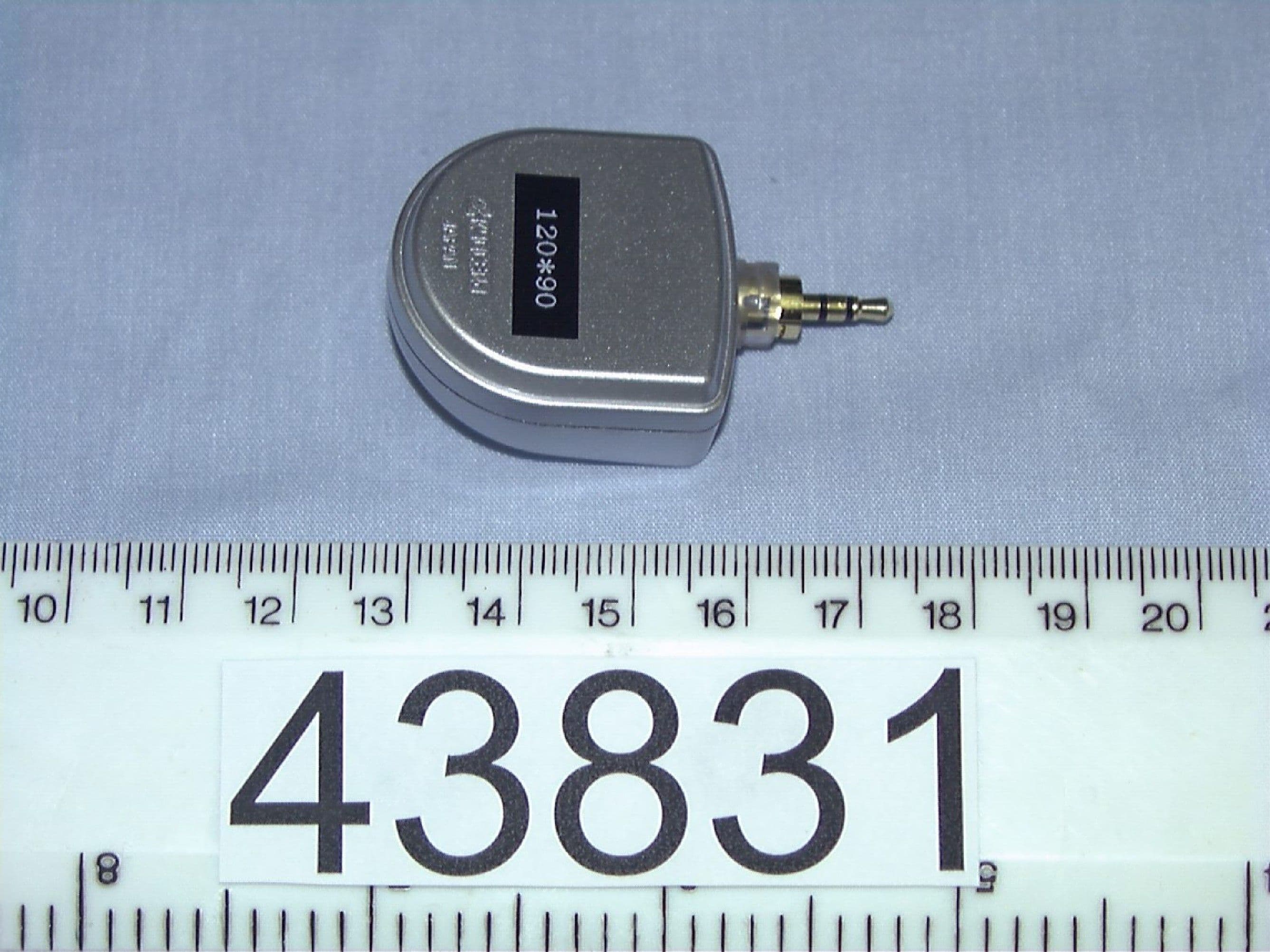
P5J-FYMASMBD-02
Sep 24, 2002PCS handset with wireless data access
Equipment Class
PCE - PCS Licensed Transmitter held to ear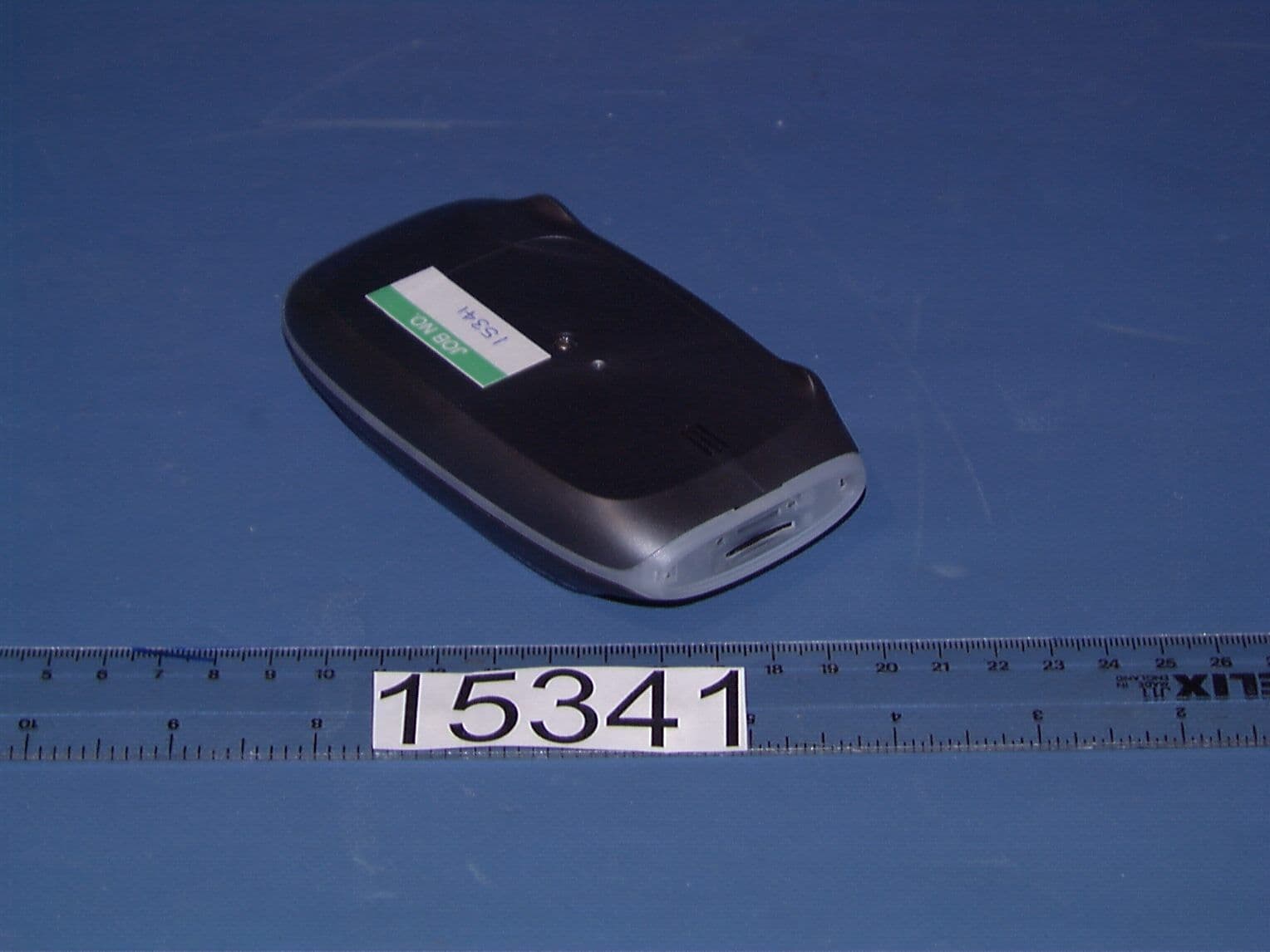
P5J-FYMASMBD-01
Aug 20, 2002PCS portable transeiver
Equipment Class
PCE - PCS Licensed Transmitter held to ear