P5MRFI150HVHF Digital Mobile Radio
STI Engineering Pty Ltd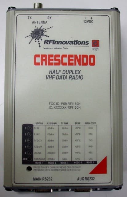
Click to zoom
Application Details
- Equipment Class
- TNB - Licensed Non-Broadcast Station Transmitter
- Date of Grant
- Dec 18, 2012
- Application Purpose
- Original Equipment
- Date of Application
- Sep 24, 2012
- Equipment Note
- VHF Digital Mobile Radio
- Frequency Range
- 150.00000000 - 174.00000000
- Company
- STI Engineering Pty Ltd
- Country
- Australia
Documents & Files
Document Text
Text extracted from the exhibit documents filed with the FCC. Open a document above to read the original.
Users Manual
CRESCENDO VHF HALF-DUPLEX USER MANUAL Crescendo VHF Half-Duplex User Manual DISCLAIMER © 2012 RF Innovations Pty Ltd. All rights reserved. RF Innovations reserves the right to make improvements on the product in this manual at any time without notice. No part of this manual may be produced, copied, translated, or transmitted in any form or by any means without the written permission of RF Innovations. Information provided in this manual is intended to be accurate and reliable. However, RF Innovations assumes no responsibility for its use or infringements upon the rights of third parties that may result from its use. Reference No. MAN00110 Revision 4.2 July 2012 Firmware Revision 1.8 Contents Crescendo VHF Half-Duplex User Manual Page 3 of 74 Contents 1. Introduction ................................................................................................................................................................................... 6 2. Installation ..................................................................................................................................................................................... 7 2.1 General considerations............................................................................................................................................................. 7 2.2 External antennas ..................................................................................................................................................................... 7 2.3 Safety and Compliance ............................................................................................................................................................. 8 2.3.1 Human Exposure to Emissions ......................................................................................................................................... 8 2.3.2 Modifications .................................................................................................................................................................... 8 3. Configuration ................................................................................................................................................................................. 9 3.1 Overview ................................................................................................................................................................................... 9 3.2 Cruise Control ........................................................................................................................................................................ 10 3.2.1 Installation ...................................................................................................................................................................... 10 3.2.2 Connecting to a Local Device ......................................................................................................................................... 10 3.2.3 Saving and Loading Configurations ............................................................................................................................... 11 3.3 Terminal Menu Interface ........................................................................................................................................................ 11 3.4 Hayes AT Command Interface ................................................................................................................................................ 12 3.5 Front Panel Interface ............................................................................................................................................................. 13 3.5.1 RSSI, Tx Power, Temperature Status (Mode 2, 3, 4) ..................................................................................................... 13 3.5.2 Main Serial Port Status (Mode 5) ................................................................................................................................... 14 3.5.3 Radio Status LEDs (Mode 1) .......................................................................................................................................... 14 4. Serial Port Operation .................................................................................................................................................................. 16 4.1 Overview ................................................................................................................................................................................. 16 4.2 Configuration ......................................................................................................................................................................... 17 4.3 Advanced Features ................................................................................................................................................................. 17 4.3.1 Control Lines .................................................................................................................................................................. 17 4.3.2 Packetiser Timers ............................................................................................................................................................ 18 4.4 Statistics .................................................................................................................................................................................. 19 5. Radio Operation .......................................................................................................................................................................... 21 5.1 Data-Driven Mode .................................................................................................................................................................. 21 5.2 Packet-Driven Mode ......…
Text truncated - open the document above for the full version.
Users Manual
CRESCENDO VHF HALF-DUPLEX USER MANUAL Crescendo VHF Half-Duplex User Manual DISCLAIMER © 2012 RF Innovations Pty Ltd. All rights reserved. RF Innovations reserves the right to make improvements on the product in this manual at any time without notice. No part of this manual may be produced, copied, translated, or transmitted in any form or by any means without the written permission of RF Innovations. Information provided in this manual is intended to be accurate and reliable. However, RF Innovations assumes no responsibility for its use or infringements upon the rights of third parties that may result from its use. Reference No. MAN00110 Revision 4.6 November 2012 Firmware Revision 1.8 Contents Crescendo VHF Half-Duplex User Manual Page 3 of 74 Contents 1. Introduction ................................................................................................................................................................................... 6 2. Installation ..................................................................................................................................................................................... 7 2.1 General considerations............................................................................................................................................................. 7 2.2 External antennas ..................................................................................................................................................................... 7 2.3 Safety and Compliance ............................................................................................................................................................. 8 2.3.1 Human Exposure to Emissions ......................................................................................................................................... 8 2.3.2 Modifications .................................................................................................................................................................... 8 3. Configuration ................................................................................................................................................................................. 9 3.1 Overview ................................................................................................................................................................................... 9 3.2 Cruise Control ........................................................................................................................................................................ 10 3.2.1 Installation ...................................................................................................................................................................... 10 3.2.2 Connecting to a Local Device ......................................................................................................................................... 10 3.2.3 Saving and Loading Configurations ............................................................................................................................... 11 3.3 Terminal Menu Interface ........................................................................................................................................................ 11 3.4 Hayes AT Command Interface ................................................................................................................................................ 12 3.5 Front Panel Interface ............................................................................................................................................................. 13 3.5.1 RSSI, Tx Power, Temperature Status (Mode 2, 3, 4) ..................................................................................................... 13 3.5.2 Main Serial Port Status (Mode 5) ................................................................................................................................... 14 3.5.3 Radio Status LEDs (Mode 1) .......................................................................................................................................... 14 4. Serial Port Operation .................................................................................................................................................................. 16 4.1 Overview ................................................................................................................................................................................. 16 4.2 Configuration ......................................................................................................................................................................... 17 4.3 Advanced Features ................................................................................................................................................................. 17 4.3.1 Control Lines .................................................................................................................................................................. 17 4.3.2 Packetiser Timers ............................................................................................................................................................ 18 4.4 Statistics .................................................................................................................................................................................. 19 5. Radio Operation .......................................................................................................................................................................... 21 5.1 Data-Driven Mode .................................................................................................................................................................. 21 5.2 Packet-Driven Mode ..…
Text truncated - open the document above for the full version.
Cover Letter(s)
----- Original Message ----- From: Lahiru Raffel To: EMC Technologies NZ Ltd Cc: Matthew Spaapen Sent: Monday, November 19, 2012 3:37 PM Subject: FCC Equipment Authorization System Good morning Regarding question 4. The radio can also operate using 4800 bps in a 6.25 kHz channel spacing. The data encoder that is used is the FX919B which is shown in the document entitled: Data encoder datasheet.pdf. This datasheet has been uploaded as an exhibit to your website On the cover page of this datasheet it states that the data modem can operate in Half Duplex mode at speeds from 4800 to 19200 bits/sec. On page 22 of the datasheet it shows that 3 symbol rates are selectable they being: - 9600 sym/sec (19200 bits/sec) - 4800 sym/sec (9600 bits/sec) - 2400 sym/sec (4800 bits/sec). I hope that this information addresses the question that has been asked Regards Lahiru Raffel Senior RF Engineer STI Engineering | Communications & Electronics Engineers Incorporating RF Innovations Office | 22 Boulder Rd, Malaga, Western Australia 6090 Telephone (Direct) | +61 8 9209 0910 Facsimile | +61 8 9248 2833 Web | www.stiengineering.com.au
Cover Letter(s)
Good morning / afternoon Below is our response to your recent review of the documentation that has been submitted ----- Original Message ----- From: [email protected] To: [email protected] Sent: Friday, November 16, 2012 11:19 AM Subject: FCC Equipment Authorization System To: f-731 Test Firm; Applicant 1) Concerning 90.210(d)(4), fyi the cross-reference to 90.210(m) is a legacy rulemaking erratum (i.e., dockets 00-32, 92-235). For equipment authorization purposes, the correct text for 90.210(d)(4) is taken to be: "For emissions beyond 50 kHz from the edge of the authorized bandwidth, see paragraph (o) (i.e., "Instrumentation") of this section." Please adjust op. desc. and/or test report exhibits as applicable. The resolution bandwidth used to define the Mask D reference level in the EMC Technologies test report has been amended from 30 kHz to 120 kHz This was a typographical error A revised test report has been uploaded In addition the operational description has been revised by the client with the original pre compliance testing results having been removed. 2) We note MPE estimation and user manual apparently show generic RF exposure compliance distance (1 m) based on Occupational/Controlled limits. Appropriate RF exposure training information and device labelling are generally required for a device to qualify for applying Occup. limits; see KDB pub 447498 D01 v05 at minimum items 3. 5), 4.1. 5), 7.; also KDB pub 865664 D02; also e.g. TIA TSB-133. In lieu of the preceding Occup. qualifications, applications should address compliance under Uncontrolled/Gen. Pop. conditions; see applicable portions of KDB pubs. 447498, 865664. Please update relevant exhibits as applicable. The MPE calculations in the EMC Technologies test report have been revised with calculations being made to the General Public limits only The safe distance in the User Manual has been revised accordingly and uploaded 3) Per 15.101(b), the receiver portion/function shall be authorized under the verification procedure. For reference we note that receiver test data herein is not applicable for 2.1033, 2.915, 2.911(b), 2.907, and 15.101 purposes. Receiver measurements made to FCC part 15 have been removed from the FCC Part 90 test report and have been reported to the client in a separate FCC part 15 test report for verification purposes 4) Please provide additional supporting information / explanation for how the equipment complies with, or is not subject to, the 90.203(j)(4)(iii) requirement to be capable of operating on channels of 6.25 kHz or less; and (alongside) the 90.203(j)(4)(iv) requirement. An explanation from my client has been uploaded which addresses this issue along with the data sheet for the data modem. The data sheet and explanation from the client shows that the radio can operate with data rates from 4800 bps on channels with spacing of 6.25 kHz and up to 19200 bps with channel spacing of 25 kHz 5) Further to 90.212(b), 90.207(l), etc., as we understand the device does not support digital voice operations; thus we note digital voice will not be authorized under this application. This transmitter is for data operations only The transmitter does not support digital voice operations The test report, operational description and user have all been checked to make sure that there is no mention of digital voice operations and no mention can be located Grantee code update A few months ago I changed the contact details of my clients grantee code (P5M) I then attempted to change the company name from RF Innovations PTY Ltd to STI Engineering I entered the details and the website said that the changes would be made by the FCC No changes seem to have been made I have also uploaded the change of company name details for the grantee code P5M which I hope you will be able to update for me regards Andrew Cutler General Manager EMC Technologies New Zealand Ltd [email protected] www.emctech.com.au Phone: +64-9-360-0862 Fax: +64-9-360-0861 Postal: PO Box 68307, Newton, Auckland, New Zealand Actual: 47 MacKelvie Street, Grey Lynn, Auckland
Cover Letter(s)
EMC Technologies NZ Ltd From:"EASADMIN" <[email protected]> To:"'Matthew Spaapen'" <[email protected]>; "EASADMIN" <EASADMIN @fcc.gov>; "'EMC Technologies NZ Ltd'" <[email protected]> Cc:"'Lahiru Raffel'" <lahiru.raffel @rfinnovations.com.au> Sent:Frida y, 31 August 2012 1:04 AM Sub ject:(PG)RE: RETRACTION: RE: (PG)RE: Change of Grantee Details Page 1 of 4 31/08/2012 Hello, The Grantee Code is P5M and the Grantee Code Registration Number is GC966523. Please retain this information for future reference. For information regarding Grantee Codes and modifying Grantee information, reference KDB Publication #204515 on KDB Home Page @ www.fcc.gov/labhelp using the KDB Publication Number Search. The Website for changing Grantee Code information is: https://apps.fcc.gov/eas/ModifyGrantee.do. The Security pop-up box may be answered Yes or No, but do not Cancel in order to proceed. Please visit https://fjallfoss.fcc.gov/coresWeb/publicHome.do to modify information related to the FCC Registration Number (FRN). Additionally, questions regarding the FRN and/or the FRN password should be directed to the FRN Help Line or the FRN Help Desk e-mail address indicated at this site. From: Matthew Spaapen [mailto:[email protected]] Sent: Wednesday, August 29, 2012 9:15 PM To: EASADMIN; 'EMC Technologies NZ Ltd' Cc: 'Lahiru Raffel' Subject: RETRACTION: RE: (PG)RE: Change of Grantee Details ... my apologies, please disregard my email. I thought you would need the old company information to obtain the Registration Number. Please use the information provided by Andrew Cutler. Matt. Thank you for the email. Please see the details below: Applicant/Grantee (company) name: RF Innovations Pty Ltd Grantee Code: P5M Name of currently listed Point of Contact (PoC): Carlos Tomaz E-mail address of current PoC [email protected] Name of New Point of Contact (PoC) Matthew Spaapen E-mail address of New PoC [email protected] Regards, Matt. Matthew Spaapen CEO STI Engineering | Communications & Electronics Engineers Incorporating RF Innovations Office | 22 Boulder Rd, Malaga, Western Australia 6090 Telephone (Direct) | +61 8 9209 0920 Facsimile | +61 8 9248 2833 Mobile | +61 (0)419 618 328 Web | www.stiengineering.com.au An STI‐Global Group Company DISCLAIMER: The information in this message and any attachments is confidential and may be legally privileged. It is intended solely for the addressee. Access to this message by anyone else is unauthorised. If you are not the intended recipient, any disclosure, copying, or distribution of the message, or any action or omission taken by you in reliance on it, is prohibited and may be unlawful. Please immediately contact the sender if you receive this message in error. Thank you. From: EASADMIN [mailto:[email protected]] Sent: Wednesday, 29 August 2012 8:35 PM To: 'EMC Technologies NZ Ltd'; EASADMIN Cc: Lahiru Raffel; '[email protected]' Subject: (PG)RE: Change of Grantee Details Hello, The Grantee Code P5M does have a Grantee Registration Number assigned to it. Please supply the answers to the list below. These information should go to the Point of Contact listed in the database but if you can provide how that is, I can give you the information. Please provide the following information regarding Grantee Code Registration Number: Applicant/Grantee (company) name: Grantee Code: Name of currently listed Point of Contact (PoC): E-mail address of current PoC Name of New Point of Contact (PoC) E-mail address of New PoC Please allow 2-3 business days for a reply. From: EMC Technologies NZ Ltd [mailto:[email protected]] Sent: Wednesday, August 29, 2012 5:27 AM To: EASADMIN Cc: Lahiru Raffel Subject: Change of Grantee Details Good morning / evening My client would like to change the company name and grantee holder details Their grantee code id P5M This code was issued prior to 2005 so they do not have a Grantee Registration Number If possible can you please change the Grantee Code details and issue my client with a Grantee Code Registration number Page 2 of 4 31/08/2012 The email address of the new grantee holder is: [email protected] Attached is a letter from my client officially requesting this change regards Andrew Cutler General Manager EMC Technologies New Zealand Ltd [email protected] www.emctech.com.au Phone: +64-9-360-0862 Fax: +64-9-360-0861 Postal: PO Box 68307, Newton, Auckland, New Zealand Actual: 47 MacKelvie Street, Grey Lynn, Auckland Matthew Spaapen CEO STI Engineering | Communications & Electronics Engineers Incorporating RF Innovations Office | 22 Boulder Rd, Malaga, Western Australia 6090 Telephone (Direct) | +61 8 9209 0920 Facsimile | +61 8 9248 2833 Mobile | +61 (0)419 618 328 Web | www.stiengineering.com.au An STI‐Global Group Company DISCLAIMER: The information in this message and any attachments is confidential and may be legally privileged. It is intended solely for the addressee. Access to this message by anyone else is unauthorised. If you are not the intended recipient, any disclosure, copying, or distribution of the message, or any action or omission taken by you in reliance on it, is prohibited and may be unlawful. Please immediately contact the sender if you receive this message in error. Thank you. From: EASADMIN [mailto:[email protected]] Sent: Wednesday, 29 August 2012 8:35 PM To: 'EMC Technologies NZ Ltd'; EASADMIN Cc: Lahiru Raffel; '[email protected]' Subject: (PG)RE: Change of Grantee Details Hello, The Grantee Code P5M does have a Grantee Registration Number assigned to it. Please supply the answers to the list below. These information should go to the Point of Contact listed in the database but if you can provide how that is, I can give you the information. Please provide the following information regarding Grantee Code Registration Number: Applicant/Grantee (company) name: Grantee Code: Name of currently listed Point of Cont…
Text truncated - open the document above for the full version.
External Photos
____________________________________________________________________________________________________________________________________________________________________________ Page 26 of 29 Test Report No 120719.1 27 h August 2012. This report may not be reproduced except in full. 10. PHOTOGRAPHS External views – Labels
ID Label/Location Info
____________________________________________________________________________________________________________________________________________________________________________ Page 26 of 29 Test Report No 120719.1 27 h August 2012. This report may not be reproduced except in full. 10. PHOTOGRAPHS External views – Labels
Internal Photos
____________________________________________________________________________________________________________________________________________________________________________ Page 27 of 29 Test Report No 120719.1 27 h August 2012. This report may not be reproduced except in full. Internal Views Top PCB – ____________________________________________________________________________________________________________________________________________________________________________ Page 28 of 29 Test Report No 120719.1 27 h August 2012. This report may not be reproduced except in full. Bottom PCB
RF Exposure Info
____________________________________________________________________________________________________________________________________________________________________________ Page 24 of 29 Test Report No 120719.1 27 h August 2012. This report may not be reproduced except in full. Exposure of humans to RF fields As per Section 1.1310 mobile transmitters are required to be operated in a manner that ensures the public is not exposed to RF energy levels in accordance with OST/OET Bulletin Number 65. Calculations have been made using the General Public/Uncontrolled Exposure limits. Minimum safe distances have been calculated below. Power density, mW/m 2 = E 2 /3770 - Occupational / Controlled Exposure limit will be 10 mW/m 2 or 60 V/m - General Population / Uncontrolled exposure limit will be 2 mW/m 2 or 28 V/m The minimum distance from the antenna at which the MPE is met is calculated from the equation relating field strength in V/m, transmit power in watts, transmit antenna gain, transmitter duty cycle and separation distance in metres: E, V/m = (√(30 * P * G * DC)) / d The rated maximum transmitter power = 5 watts. Transmitter is operated using an antenna with a gain of up to 20 (13dB). The client has declared a duty cycle of 100% Controlled Uncontrolled d = √ (30 * P * G*DC) / E d = √ (30 * 5 * 20 * 1 ) / 60 d = √ (30 * 5 * 20 * 1) / 28 d = 0.91 metres or 91 cm d = 1.95 metres or 195 cm Result: Complies if the safe distances defined for each environment are applied.
RF Exposure Info
____________________________________________________________________________________________________________________________________________________________________________ Page 21 of 27 Test Report No 120719.1a 27 h August 2012 This report may not be reproduced except in full. Exposure of humans to RF fields As per Section 1.1310 mobile transmitters are required to be operated in a manner that ensures the public is not exposed to RF energy levels in accordance with OST/OET Bulletin Number 65. Calculations have been made using the General Public Exposure limits. Minimum safe distances have been calculated below. Power density, mW/m 2 = E 2 /3770 - General Public / Uncontrolled exposure limit will be 2 mW/m 2 or 28 V/m The minimum distance from the antenna at which the MPE is met is calculated from the equation relating field strength in V/m, transmit power in watts, transmit antenna gain, transmitter duty cycle and separation distance in metres: E, V/m = (√(30 * P * G * DC)) / d The rated maximum transmitter power (P) = 5 watts. Transmitter is operated using an antenna with a gain (G) of up to 20 (13 dBi). The client has declared a duty cycle (DC) of 100% General Public / Uncontrolled d = √ (30 * P * G*DC) / E d = √ (30 * 5 * 20 * 1) / 28 d = 1.95 metres or 195 cm Result: Complies if the above safe distance is defined in the user manual for this equipment.
Test Report
____________________________________________________________________________________________________________________________________________________________________________ Page 1 of 28 Test Report No 120719.1 27 h August 2012. This report may not be reproduced except in full. EMC Technologies (NZ) Ltd PO Box 68-307 Newton, Auckland Phone 09 360 0862 Fax 09 360 0861 E-Mail Address: [email protected] Web Site: www.emctech.com.au TEST REPORT Crescendo RFI-150 (HWHDD01 & HNMDD01) VHF Digital Modem tested to the Code of Federal Regulations (CFR) 47 Part 90 –Private Land Mobile Services Part 15 – Radio Frequency Devices for STI Engineering This Test Report is issued with the authority of: ______________________________________ Andrew Cutler - General Manager ____________________________________________________________________________________________________________________________________________________________________________ Page 2 of 28 Test Report No 120719.1 27 h August 2012. This report may not be reproduced except in full. Table of Contents 1. COMPLIANCE STATEMENT 3 2. RESULT SUMMARY 3 3. ATTESTATION 4 4. CLIENT INFORMATION 5 5. TEST SAMPLE DESCRIPTION 5 6. TEST RESULTS 7 7. TEST EQUIPMENT USED 24 8. ACCREDITATIONS 24 9. PHOTOGRAPHS 25 ____________________________________________________________________________________________________________________________________________________________________________ Page 3 of 28 Test Report No 120719.1 27 h August 2012. This report may not be reproduced except in full. 1. COMPLIANCE STATEMENT The Crescendo RFI-150 (HWHDD01 & HNMDD01) VHF Digital Modem complies with the limits defined in 47 CFR Part 15, 47 CFR Part 90 and 47 CFR Part 2 when tested in- accordance with the test methods described in 47 CFR Part 2 and ANSI C63.4, 2002. 2. RESULT SUMMARY The results of testing, carried out in 6 th – 10 th August 2012, are summarised below. Clause Description Result 90.203 Certification required Noted 2.1046 90.205 RF power output Power and antenna height limits Noted Complies 2.1047 2.1047(a) 2.1047(b) Modulation Characteristics Low pass filter response Modulation limiting characteristics Noted Noted Noted 2.1049 2.202 90.207 90.209 90.210 Occupied bandwidth Bandwidths Types of emissions Bandwidth limitations Emission masks Noted Noted Complies Complies Complies 2.1051 Spurious emissions at antenna terminals Complies 2.1053 Field strength of spurious radiation Complies 2.1055 22.355 90.213 Frequency stability Frequency stability Frequency stability Noted Complies Complies 90.214 Transient frequency behaviour Complies 15.109 15.111 Receiver radiated emissions Receiver local oscillator voltage Complies Compl…
Text truncated - open the document above for the full version.
Contact Information
Applicant
Johan Svean(Managing Director)
Test Firm
EMC Technologies NZ Ltd.Andrew Cutler
Technical Specifications
| # | Rule Parts | Frequency Range | Power Output | Emission | Tolerance |
|---|---|---|---|---|---|
| 2 | 9 | 150 MHz - 174 MHz | 5 W | 20K0F1D | 2.5 ppm |
Other Applications from STI Engineering Pty Ltd
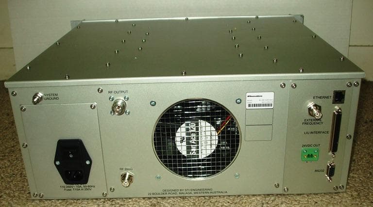
P5MRFI400
Aug 07, 2023RFI-400 250W UHF Paging Transmitter
Equipment Class
TNB - Licensed Non-Broadcast Station Transmitter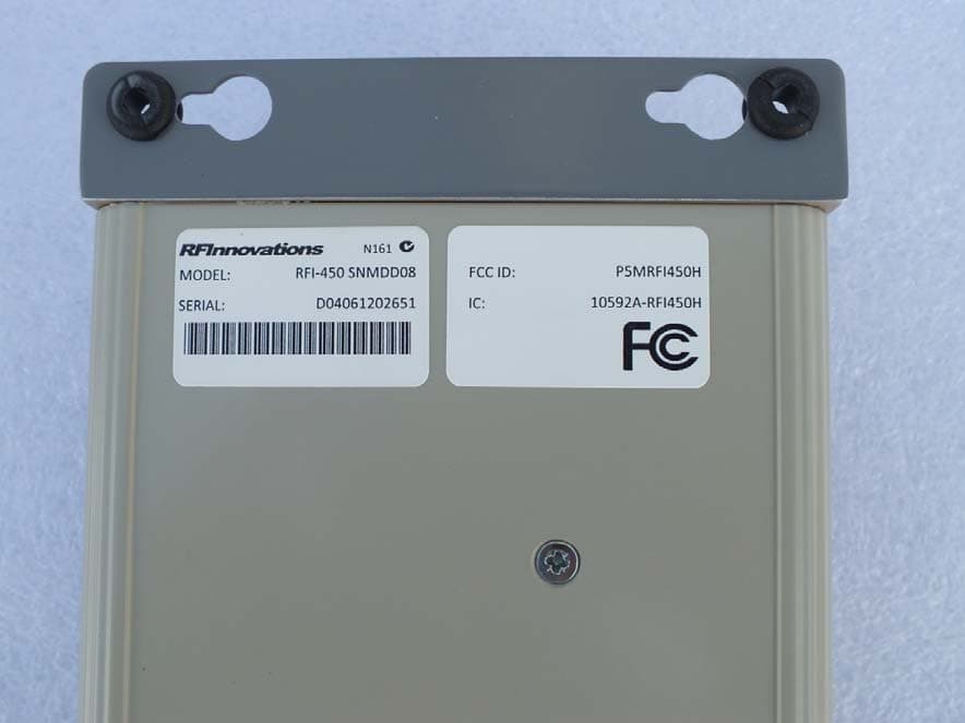
P5MRFI450H
Nov 05, 2013UHF DIGITAL MOBILE RADIO
Equipment Class
TNB - Licensed Non-Broadcast Station Transmitter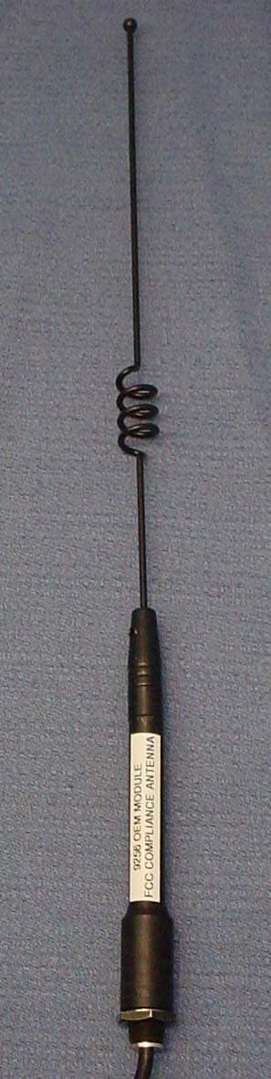
P5M9256OEM
Aug 31, 2004Radio Modem Module
Equipment Class
DSS - Part 15 Spread Spectrum Transmitter
P5M9256TRX
Apr 02, 2002Frequency Hopping Spread Spectrum Transceiver
Equipment Class
DSS - Part 15 Spread Spectrum Transmitter