P5S-DT200SDigital Video/Audio Transmitter
Pacific Microwave Research, Inc.
Click to zoom
Application Details
- Equipment Class
- TNB - Licensed Non-Broadcast Station Transmitter
- Date of Grant
- Nov 07, 2006
- Application Purpose
- Original Equipment
- Date of Application
- Sep 10, 2006
- Equipment Note
- Digital Video/Audio Transmitter
- Frequency Range
- 2450.00000000 - 2483.50000000
- Country
- United States
Documents & Files
Document Text
Text extracted from the exhibit documents filed with the FCC. Open a document above to read the original.
Users Manual
Pacific Microwave Research, Inc. DT-200 Digital Microwave Video & Audio Transmitter USER’S MANUAL Pacific Microwave Research, Inc. 1485 Poinsettia Avenue, Suite 111 Vista, CA 92083 760.295.5416 www.pmicrowave.com 2 IMPORTANT WARNING! THIS EQUIPMENT WILL POSE A RADIATION HAZARD IF IMPROPERLY HANDLED Pacific Microwave Research, Inc. (PMR), in compliance with RF exposures limits set forth in OET Bulletin 65 , Fourth Edition, August, 1999. 1 The following text is intended to notify the user of PMR’s transmitter equipment that a radiation hazard could exist if the DT-200S transmitter is improperly operated. The user should carefully read and understand this section before operating equipment. PMR’s DT-200S microwave transmitter is rated at 0.1W (+20 dBm) nominal RF power output and has been designed as an intentional radiator. The device can deliver video and audio signals over short ranges when used with PMR’s DR-200S receiver and appropriate antennas in either fixed or mobile applications. When the DT-200S transmitter is operating into an antenna, the system is emitting radio frequency energy! An internal RF isolator prevents emission of energy at the antenna terminal when no antenna is connected even when the transmitter is powered up. Because the DT-200S is an isolator protected low power device, there is no hazard potential until a proper antenna is connected to the RF output terminal. Safe operating procedures must be observed when the unit is transmitting into an antenna. Exposure is based upon the average amount of time spent within an electromagnetic field (RF energy) with a given intensity (field intensity in mW/ cm 2 ). There are two categories of exposure situations; occupational/controlled and general population/uncontrolled. Occupational/controlled limits apply in situations in which persons are exposed as a consequence of their employment provided those persons are fully aware of the potential for exposure and can exercise control over their exposure. These limits apply in situations when an individual is transient through a location where occupational/controlled limits apply provided the individual is made aware of the potential for exposure. General population/uncontrolled exposures apply in situations in which the general public may be exposed, or in which persons that are exposed as a consequence of their employment may not be fully aware of the potential for exposure or can not exercise control over their exposure. Exposure may be controlled by observing the safe distances found in the Table below and remaining beyond those distances from the antenna at all times when the transmitter is operational. At no time should the user remain within a distance less than the indicated safe distance for a period greater than 30 minutes. 1 The complete text may be found at: www.fcc.gov/bureaus/engineering_technology/documents/bulletins/oet65/oet65.pdf 3 The safe distance is based on the MPE exposure limits identified in Table 1. (FCC Limits for Maximum Permissible Exposure) of OST 65. The maximum power density allowed at 2400 MHz is 5 mW/cm 2 for occupational/controlled exposure, and 1 mW/cm 2 for general population/uncontrolled exposure. For fixed operations, based upon a maximum transmitter power output of 0.1W with an antenna gain of +2 dBi, the safe distance is greater than 4 cm from the antenna for both controlled and uncontrolled exposure. Exposure level is relative to antenna gain. Gain antennas (parabolic dish, horn, helical, Yagi, etc.) will increase the safe distance required. Table 1 indicates the safe distance for fixed operations, within the main beam of the antenna, based upon a maximum transmitter power output of 0.1W with an antenna gain of +2 dBi. Frequency – 2400 MHz TX Power – 0.1W (+20 dBm) Antenna Gain - +2 dBi Safe Distance from Antenna Under Fixed Conditions Controlled Exposure (5 mW/cm 2 ) Uncontrolled Exposure (1 mW/cm 2 ) 1.4 cm 3.2 cm If the DT-100S is operated at a fixed location and other transmitters are co-located, the user must consider exposure as a result of the aggregate collection of transmitters at the location. Increases of four times in radiated energy level will double the safe distance. The user must calculate the safe distance for any given case based on the antenna gain required for the application. Pacific Microwave Research can provide such calculations in consultation with the user if required. Contact PMR at 760.295.5416 for additional information. Table 1. FCC limits for MPE based on OST 65 for PMR DT-200S Pacific Microwave Research, Inc. DT-200 User’s Manual ©2006 1 1.1 Introduction The DT-200 Digital COFDM Microwave Video and Audio Transmitter from Pacific Microwave Research is a compact transmitter designed for short-range transmission applications. Common uses include remote broadcasting (ENG, EFP), law enforcement surveillance and video collection. The DT-200 is a compact unit designed for portable and fixed applications and transmits remote video to a central receive location. The DT- 200 is designed to transmit one NTSC (or PAL) video signal plus two high quality audio signals and an RS-232 data channel. The DT-200 operates from a nominal +12 Vdc power source and is capable of up to 100mW of output power. The DT-200 uses Coded Orthogonal Frequency Division Multiplex (COFDM) modulation to overcome the effects of multipath. 2.0 Operation The following section describes the proper operating techniques for the DT-200 transmitter including power, antenna, video, and audio connections. The DT-200 generates heat during normal operation. The user should give careful consideration to mounting the transmitter in such a way as to insure heat is directed away from the housing. An external heatsink may be desirable in some operational modes. 2.1 Primary Connections A number of connections must be made in order for the DT-200 to operate properly. These include dc power; transmit antenna, and video input. WARNING Prior to transmitting , the user …
Text truncated - open the document above for the full version.
Cover Letter(s)
1 PMR Memorandum To : Federal Communications Commission CC: DT-200S File From: Christopher M. Durso Date: 11-Sep-06 Re: Request for Confidentiality Dear Sirs; This letter is to request confidentiality with respect to an FCC Type Certification submission made by Pacific Microwave Research, Inc. (PMR) for its DT-200S microwave transmitter. Please apply confidentiality to the following submissions: DT-200S Schematics DT-200S Tune-up Procedure DT-200S Parts List / Bill of Materials The information contained in these submissions includes PMR company proprietary intellectual property and data representing a competitive advantage to the corporation. Release of this data would harm PMR’s ability to remain viable in the marketplace. This request is made pursuant to §0.459 and §0.457(d)(ii) of the Commission’s Rules. Thank you for you consideration in this matter. Best regards, Christopher M. Durso President DT-200S
External Photos
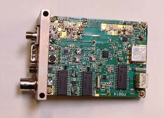
Exhibit Showing Exterior and Interior of EUT DT-200S Fig 7. DT-200S Front Side Fi g 8. DT-200S Rear Side Fig 9. DT-200S Interior Bottom Fig 10. DT-200S Interior Top
ID Label/Location Info
Exhibit pursuant to 47CFR 2.925 – Identification of Equipment Following issuance of the Certification of the PMR DT-200S, each unit will be affixed with an identification label per §2.926 containing the equipment model number, description, part number, serial number, and FCC Identifier as shown in Figure 5. Fig 5. Vinyl Equipment ID label affixed to DT-200S transmitter Fig 6. DT-200S with FCC ID Label Part No: 101558 Serial No: 1727 FCC ID: P5S-DT200S Transmitter, DT200S, Compact COFDM Digital, S- band (1990 – 2700) Front of Unit
Internal Photos
Exhibit Showing Exterior and Interior of EUT DT-200S Fig 7. DT-200S Front Side Fi g 8. DT-200S Rear Side Fig 9. DT-200S Interior Bottom Fig 10. DT-200S Interior Top
Operational Description
Operational Description of Pacific Microwave Research DT-200S Microwave Video/Audio Transmitter Introduction The DT-200S Microwave Video and Audio Transmitter from Pacific Microwave Research is a compact transmitter designed for short-range transmission applications under FCC Part 90 and Part 74. Common uses include law enforcement surveillance and electronic field production. The DT-200 is a compact unit designed for portable and field applications to transmit remote video to a central receive location. The DT-200S is designed to transmit one NTSC (or PAL) video signal plus two high quality audio signals. The DT-200S operates from a nominal +12 Vdc power source and is capable of 0.1Watts of output power. The DT-200S may be equipped with up to 10 channels consistent with parameters listed on the user’s FCC station license. Power Supply The DT-200S power supply is housed in a common housing with the transmitter and produces all required DC voltages for the operation of the transmitter. Nominal input voltage is in the range of +11 – +36 Vdc with a typical current consumption of 1.2 A @12Vdc. Primary power is applied to J3 Pin A with the return on J3 Pin C. Reverse polarity protection is provided by D2. Voltage regulator U9 regulates the primary input voltage to +5.0 Vdc for application to the microprocessor (U8), the RF power amplifier (U11), modulator (U16) and subsequent regulation. This +5 Vdc is then converted to 3.3 Vdc by U10 for application to the clock oscillator (U13). U12 converts regulated +5 Vdc to -5 Vdc for application to the video and audio amplifiers (U7, U22, U23, and U24). U14 converts the +5 Vdc regulated voltage to +15 Vdc for application to the phase-lock-loop (PLL U21) and loop filter (U20). Frequency Generation The output frequency of the DT-200S is generated by the combination of PLL (U21), loop filter (U20), and VCO (U17). The frequency of operation is loaded into the serial PLL by microprocessor (U8) according to the position of the selector switch (S1) or via RS-232 command (U11). The customer channel table is stored in the microprocessor (U21). Frequency data is input to U21 through RS-232 (U11) at the time of manufacture. A clock oscillator (U13) operates at a frequency of 16 MHz and provides primary frequency stability for the transmitter. The tuning voltage from U20 is applied to the VCO (U17). The output of U17 is sampled for input to the PLL (U21). The sample signal is compared to the desired frequency and an error tuning voltage is applied to U20 to maintain operating frequency. Video Modulation Video modulation is applied to the video encoder module through front panel BNC connector J4. The video encoder converts the analog video signal (NTSC or PAL) to an MPEG2 compressed digital video signal. The video signal is multiplexed into a serial data stream with the digital audio signal and transformed into a balanced quadrature signal consisting of in-phase (I) and quadrature-phase (Q) signals representing the COFDM waveform. The I/Q signals are applied to the modulator (U1) resulting in an 8 MHz wide digital signal. The output level of the modulator is maintained at a precise level by the combination of U2, U5, and U3. A voltage controlled step attenuator (U2) is controlled by the microprocessor (U8) through a digital-to-analog converter (U5) and dc amplifier (U3) to adjust the modulator level to the voltage-controlled-oscillator (VCO) as the operating frequency is adjusted. Temperature stability is maintained by U4. The leveled output of the modulator (U2) is applied to the VCO (U17). Audio Modulation Audio modulation is applied to U24 which acts as a balanced to unbalanced amplifier. Audio levels are controlled via the microprocessor (U8) by the digital attenuator (U22). The output of each audio channel is amplified by U23A:B and then applied to the audio encoder module. The audio encoder digitizes the audio and multiplexes it into a serial data stream along with the video signal as above. RF Amplification Modulated RF energy is output from the VCO (U17) and amplified by U18. This output is up-converted by application to a 2X frequency multiplier (U19) and subject to filtering by FL1 and additional gain by U25. The output of U25 is fed to the power amplifier board. The power amplifier board provides additional gain (U2) and filtering (FL1) prior to application to the final amplifier stage (U1). The RF output of U1 is applied to isolator ISO 1. This provides greater than 20 dB of isolation between the output device and the antenna. The isolator prevents reflections from poor antenna matches from entering the sampling circuit and causing PLL locking problems. Finally, the output is applied to a low pass filter with a cutoff frequency of 3300 MHz. This filter prevents the transmission of any harmonic signals that may have been generated in the transmitter as well as those that could be generated as a result of the non-linear characteristics of the ferromagnetic isolator. The output of the filter is connected to a front panel female SMA connector. In the event of a PLL unlock condition, the microprocessor (U8) commands the power amplifier (U1) to the standby condition to prevention the transmission of energy on a frequency not licensed to the user.
RF Exposure Info
Exhibit pursuant to Human Exposure Guideline to Radio Frequency Energy and Warning Label affixed to DT-200S The following text is included at the front of the operating manual for the DT-200S to educate the users regarding Radio Frequency Radiation Hazards. Additionally, a warning label is attached to the DT-200S to direct the user to read and comply with the information contained in the user manual with respect to RF radiation hazards. IMPORTANT WARNING! THIS EQUIPMENT WILL POSE A RADIATION HAZARD IF IMPROPERLY HANDLED Pacific Microwave Research, Inc. (PMR), in compliance with RF exposures limits set forth in OET Bulletin 65, Fourth Edition, August, 1999. 1 The following text is intended to notify the user of PMR’s transmitter equipment that a radiation hazard could exist if the DT-200S transmitter is improperly operated. The user should carefully read and understand this section before operating equipment. PMR’s DT-200S microwave transmitter is rated at 0.1W (+20 dBm) nominal RF power output and has been designed as an intentional radiator. The device can deliver video and audio signals over short ranges when used with PMR’s DR-200S receiver and appropriate antennas in either fixed or mobile applications. When the DT-200S transmitter is operating into an antenna, the system is emitting radio frequency energy! An internal RF isolator prevents emission of energy at the antenna terminal when no antenna is connected even when the transmitter is powered up. Because the DT-200S is an isolator protected low power device, there is no hazard potential until a proper antenna is connected to the RF output terminal. Safe operating procedures must be observed when the unit is transmitting into an antenna. Exposure is based upon the average amount of time spent within an electromagnetic field (RF energy) with a given intensity (field intensity in mW/ cm 2 ). There are two categories of exposure situations; occupational/controlled and general population/uncontrolled. Occupational/controlled limits apply in situations in which persons are exposed as a consequence of their employment provided those persons are fully aware of the potential for exposure and can exercise control over their exposure. These limits apply in situations when an individual is transient through a location where occupational/controlled limits apply provided the individual is made aware of the potential for exposure. 1 The complete text may be found at: www.fcc.gov/bureaus/engineering_technology/documents/bulletins/oet65/oet65.pdf General population/uncontrolled exposures apply in situations in which the general public may be exposed, or in which persons that are exposed as a consequence of their employment may not be fully aware of the potential for exposure or can not exercise control over their exposure. Exposure may be controlled by observing the safe distances found in the Table below and remaining beyond those distances from the antenna at all times when the transmitter is operational. At no time should the user remain within a distance less than the indicated safe distance for a period greater than 30 minutes. The safe distance is based on the MPE exposure limits identified in Table 1. (FCC Limits for Maximum Permissible Exposure) of OST 65. The maximum power density allowed at 2400 MHz is 5 mW/cm 2 for occupational/controlled exposure, and 1 mW/cm 2 for general population/uncontrolled exposure. For fixed operations, based upon a maximum transmitter power output of 0.1W with an antenna gain of +2 dBi, the safe distance is greater than 4 cm from the antenna for both controlled and uncontrolled exposure. Exposure level is relative to antenna gain. Gain antennas (parabolic dish, horn, helical, Yagi, etc.) will increase the safe distance required. Table 1 indicates the safe distance for fixed operations, within the main beam of the antenna, based upon a maximum transmitter power output of 0.1W with an antenna gain of +2 dBi. Frequency – 2400 MHz TX Power – 0.1W (+20 dBm) Antenna Gain - +2 dBi Safe Distance from Antenna Under Fixed Conditions Controlled Exposure (5 mW/cm 2 ) Uncontrolled Exposure (1 mW/cm 2 ) 1.4 cm 3.2 cm If the DT-100S is operated at a fixed location and other transmitters are co-located, the user must consider exposure as a result of the aggregate collection of transmitters at the location. Increases of four times in radiated energy level will double the safe distance. The user must calculate the safe distance for any given case based on the antenna gain required for the application. Pacific Microwave Research can provide such calculations in consultation with the user if required. Contact PMR at 760.295.5416 for additional information. Table 1. FCC limits for MPE based on OST 65 for PMR DT-200S SAMPLE CALCULATIONS Equation: Pd EIRPmW r • = π4 Example: Fixed use with 2dBi antenna under uncontrolled conditions. 0.14 130 • = π r Example: Fixed use with 2dBi antenna under controlled conditions. 0.54 130 • = π r Where: r= safe distance in cm EIRPmW = TX power(dBm) plus Antenna gain (dBi) in mW {referenced to isotropic radiator} Pd= Power density in cm 2 (1 or 5) Where: r= 3.2 cm EIRPmW = +22 dBm (20 + 2) =130 mW Pd= Power density 1cm 2 Where: r= 1.4 cm EIRPmW = +22 dBm (20 + 2) = 130 mW Pd= Power density 5cm 2 Warning Label affixed to DT-200S
Test Report
Pacific Microwave Research, Inc. DT-200 Type Certification, 2006 Technical Measurements and Records in Support of FCC Type Certification under 47CFR Part 90 and 47CFR Part 74 for a Microwave Video and Audio Transmitter Manufactured and Submitted by: Pacific Microwave Research, Inc. 1485 Poinsettia Avenue, Suite #111 Vista, CA 92081 Tel: 760-295-5416 www.pmicrowave.com FRN # 0006-0883-48 Grantee Code – P5S Product Model # - DT-200S Point of Contact: Administrative Mr. Christopher M. Durso President, PMR Technical Mr. A. David Dirdo Chief Technical Officer, PMR September 11, 2006 Pacific Microwave Research, Inc. DT-200 Type Certification, 2006 Pacific Microwave Research, Inc. (PMR) is a California Corporation engaged in the design and manufacture of wireless transmission and reception equipment for the transport of video and audio signals using frequency bands above 1900 MHz. One such design, the DT-200S, is a compact microwave transmitter capable of operation in bands over the range of 1900 – 2700 MHz. This transmitter is designed to transmit standard NTSC or PAL video signals along with two audio and one data signal over a short range to a compatible receiver. Applications include: law enforcement surveillance, remote video telemetry, and broadcast EFP and ENG. All designs are the intellectual property of Pacific Microwave Research, Inc. The PMR DT-200S has been tested per §2.907 and §2.947 for conformance with the rules under 47CFR Part 90 and 47CFR Part 74. A data sheet for this product is contained in the Appendix as well as a copy of the standard transmitter test data record that accompanies each unit manufactured. The testing for this submission was conducted at PMR’s design and manufacturing facility located at 1485 Poinsettia Avenue, Suite 111, Vista, CA, by Mr. A. David Dirdo, Chief Technical Officer, PMR. The testing was witnessed and results verified by Mr. Christopher M. Durso, President, PMR. All tests were carried out with calibrated laboratory grade electronic test equipment using industry accepted procedures and techniques. The principles conducting the tests have collectively over 30 years in rf, microwave, and related fields. The results of those tests are contained in this submittal. A block diagram and photograph of the test set-up is contained in this submission to help the evaluator understand the test conditions. No modifications to the EUT (DT-200S) were required during the testing regime to insure compliance with any of the rule sections cited. The tests and results reported in this document were conducted on September 10, 2006 by the undersigned. Test Conductor: Verified by: I attest to the accuracy of the data I attest to the accuracy of the data contained in this submission. contained in this submission. ___________________________ _____________________________ Mr. A. David Dirdo Mr. Christopher M. Durso Chief Technical Officer, PMR President, PMR Pacific Microwave Research, Inc. DT-200 Type Certification, 2006 Exhibit pursuant to 47CFR 90.205 – Power and antenna height limits The Pacific Microwave Research DT-200S transmitter is rated at 0.1W (+20 dBm) output power over the operating voltage and frequency range. At no time will the transmitter exceed the maximum power output of 5W (+37 dBm) as required by §90.205(n) or 12W (+41 dBm) as required by §74.636. The data tabulated below in Table 1. was compiled by PMR using the EUT DT-200S transmitter and the measurement equipment shown in the block diagram test set-up on page 8. The transmitter was terminated into the 50 Ω input of the power meter (§2.1046(a)). The test was run over the rull range of specified input voltage (§2.1055(d)). Input Voltage Vdc Frequency of Operation MHz RF Power Output dBm 10.5 2459.0 +21 12.0 2459.0 +21 14.0 2459.0 +21 18.0 2459.0 +21 24.0 2459.0 +21 32.0 2459.0 +21 Exhibit pursuant to 47CFR 90.207 & 47CFR 74.462 – Types of Emissions The Pacific Microwave Research DT-200S transmitter is designed to transmit one NTSC (EIA 250C) or PAL compatible television signal along with two audio and one data channel utilizing coded orthogonal frequency division multiplex modulation (COFDM). COFDM is a multi-carrier digital modulation scheme. The emission designator of this complex modulation is 8M6D7W as per §2.201. Table 1. Frequency & Power Output vs. Input Voltage - THIS SPACE INTENTIONALLY BLANK - Pacific Microwave Research, Inc. DT-200 Type Certification, 2006 Exhibit pursuant to 47CFR 90.209 – Bandwidth Limitations The occupied bandwidth per §2.202 of the Pacific Microwave Research DT-200S transmitter 7.86 MHz. The digitally modulated transmission consists of 1705 orthogonal spaced 4.4 kHz apart. A specrtograph of the modulated waveform is shown below in FIGURE 1. (occupied bandwidth spectral measurement represents in-band energy -20 dBc from peak) Fig 1. DT-200S Spectrograph of Occupied Bandwidth (V=5dB/div H=1 MHz/div) Pacific Microwave Research, Inc. DT-200 Type Certification, 2006 Exhibit pursuant to 47CFR 90.210 – Emission Masks The Pacific Microwave DT-200S complies with the requirements of the emission mask as stated in §90.210(c) and §74.637. Harmonic supression of the transmitter is accomplished using an integral low pass filter (LPF 3300) between the power amplifier output stage and the antenna terminal (§2.1033(c)(10). An internal unsaturated ferro- magnetic isolator (ISO1) provides additional suppression of out-of-band energy. The requirement contained in §90.210(c)(1) is within the modulation bandwidth of the authorized emission (8M6D7W) and is not applicable in this case. With respect to §90.210(c)(2) and §74.637, emissions removed from the fundamental by 20 MHz (250% bandwidth) were measured greater than –68 dBc in compliance with the requirement (29 log 45 2 / 11 dB or 65.6 dBc) for such suppression. Fig 2. DT-200S Spectrograph of Spectral Purity (V=10dB/div H=50 MHz/div) Pacific Microwave Research, Inc. DT-200 Type Certification, 2006 With respect to §90.210(c)(3) and §74.637…
Text truncated - open the document above for the full version.
Test Report
Pacific Microwave Research, Inc. DT-200 Type Certification, 2006 Test Report Revision 01 – 07OCT06 Technical Measurements and Records in Support of FCC Type Certification under 47CFR Part 90 and 47CFR Part 74 for a Microwave Video and Audio Transmitter Manufactured and Submitted by: Pacific Microwave Research, Inc. 1485 Poinsettia Avenue, Suite #111 Vista, CA 92081 Tel: 760-295-5416 www.pmicrowave.com FRN # 0006-0883-48 Grantee Code – P5S Product Model # - DT-200S Point of Contact: Administrative Mr. Christopher M. Durso President, PMR Technical Mr. A. David Dirdo Chief Technical Officer, PMR September 14, 2006 Pacific Microwave Research, Inc. DT-200 Type Certification, 2006 Test Report Revision 01 – 07OCT06 Pacific Microwave Research, Inc. (PMR) is a California Corporation engaged in the design and manufacture of wireless transmission and reception equipment for the transport of video and audio signals using frequency bands above 1900 MHz. One such design, the DT-200S, is a compact microwave transmitter capable of operation in bands over the range of 1900 – 2700 MHz. This transmitter is designed to transmit standard NTSC or PAL video signals along with two audio and one data signal over a short range to a compatible receiver. Applications include: law enforcement surveillance, remote video telemetry, and broadcast EFP and ENG. All designs are the intellectual property of Pacific Microwave Research, Inc. The PMR DT-200S has been tested per §2.907 and §2.947 for conformance with the rules under 47CFR Part 90 and 47CFR Part 74. A data sheet for this product is contained in the Appendix as well as a copy of the standard transmitter test data record that accompanies each unit manufactured. The testing for this submission was conducted at PMR’s design and manufacturing facility located at 1485 Poinsettia Avenue, Suite 111, Vista, CA, by Mr. A. David Dirdo, Chief Technical Officer, PMR. The testing was witnessed and results verified by Mr. Christopher M. Durso, President, PMR. All tests were carried out with calibrated laboratory grade electronic test equipment using industry accepted procedures and techniques. The principles conducting the tests have collectively over 30 years in rf, microwave, and related fields. The results of those tests are contained in this submittal. A block diagram and photograph of the test set-up is contained in this submission to help the evaluator understand the test conditions. No modifications to the EUT (DT-200S) were required during the testing regime to insure compliance with any of the rule sections cited. The tests and results reported in this document were conducted on September 10, 2006 by the undersigned. Test Conductor: Verified by: I attest to the accuracy of the data I attest to the accuracy of the data contained in this submission. contained in this submission. ___________________________ _____________________________ Mr. A. David Dirdo Mr. Christopher M. Durso Chief Technical Officer, PMR President, PMR Pacific Microwave Research, Inc. DT-200 Type Certification, 2006 Test Report Revision 01 – 07OCT06 Exhibit pursuant to 47CFR 90.205 – Power and antenna height limits The Pacific Microwave Research DT-200S transmitter is rated at 0.1W (+20 dBm) output power over the operating voltage and frequency range. At no time will the transmitter exceed the maximum power output of 5W (+37 dBm) as required by §90.205(n) or 12W (+41 dBm) as required by §74.636. The data tabulated below in Table 1 (for operation in Part 90) was compiled by PMR using the EUT DT-200S transmitter and the measurement equipment shown in the block diagram test set-up on page 8. The transmitter was terminated into the 50 Ω input of the power meter (§2.1046(a)). The test was run over the full range of specified input voltage (§2.1055(d)). Table 2 shows the data tabulated for operation in Part 74 under the same operating conditions. Input Voltage Vdc Frequency of Operation MHz RF Power Output dBm 10.5 2459.0 +21 12.0 2459.0 +21 14.0 2459.0 +21 18.0 2459.0 +21 24.0 2459.0 +21 32.0 2459.0 +21 Input Voltage Vdc Frequency of Operation MHz RF Power Output dBm 10.5 2079.5 +21 12.0 2079.5 +21 14.0 2079.5 +21 18.0 2079.5 +21 24.0 2079.5 +21 32.0 2079.5 +21 Exhibit pursuant to 47CFR 90.207 & 47CFR 74.462 – Types of Emissions The Pacific Microwave Research DT-200S transmitter is designed to transmit one NTSC (EIA 250C) or PAL compatible television signal along with two audio and one data channel utilizing coded orthogonal frequency division multiplex modulation (COFDM). COFDM is a multi-carrier digital modulation scheme. The emission designator of this complex modulation is 8M6D7W as per §2.201. Table 1. Frequency & Power Output vs. Input Voltage (Part 90) Table 2. Frequency & Power Output vs. Input Voltage (Part 74) Pacific Microwave Research, Inc. DT-200 Type Certification, 2006 Test Report Revision 01 – 07OCT06 Exhibit pursuant to 47CFR 90.209 – Bandwidth Limitations The occupied bandwidth per §2.202 of the Pacific Microwave Research DT-200S transmitter 7.86 MHz. The digitally modulated transmission consists of 1705 orthogonal carriers spaced 4.4 kHz apart. A spectrograph of the modulated waveform is shown below in FIGURE 1 for operation in Part 90. FIGURE 2 shows the modulated waveform in Part 74. (occupied bandwidth spectral measurement represents in-band energy -20 dBc from peak) Fig 1. DT-200S Spectrograph of Occupied Bandwidth (Part 90) (V=5dB/div H=1 MHz/div) Pacific Microwave Research, Inc. DT-200 Type Certification, 2006 Test Report Revision 01 – 07OCT06 Exhibit pursuant to 47CFR 90.210 – Emission Masks The Pacific Microwave D…
Text truncated - open the document above for the full version.
Contact Information
Applicant
Christopher Durso(President)
Technical Contact
Pacific Microwave Research, Inc.Alex David Dirdo
[email protected]760-295-5416
1485 Poinsettia Avenue · Vista, California · United States
Non-Technical Contact
Pacific Microwave Research, Inc.Christopher Michael Durso
[email protected]760-295-5416
Technical Specifications
| # | Rule Parts | Frequency Range | Power Output | Emission | Tolerance |
|---|---|---|---|---|---|
| 2 | 74,9 | 2.45 GHz - 2.48 GHz | 100.00 mW | 8M6D7W | 0.00025 % |
Other Applications from Pacific Microwave Research, Inc.
P5SAT100C3
Apr 05, 2004Microwave Video and Audio Transmitter
Equipment Class
TNB - Licensed Non-Broadcast Station Transmitter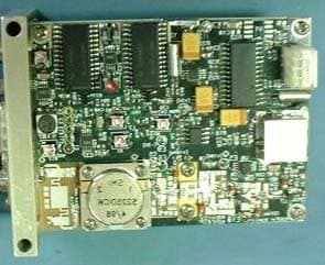
P5SAT100S
Sep 23, 2002Microwave Video and Audio Transmitter
Equipment Class
TNB - Licensed Non-Broadcast Station Transmitter