P5SAT100SMicrowave Video and Audio Transmitter
Pacific Microwave Research, Inc.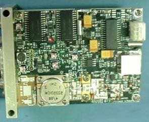
Click to zoom
Application Details
- Equipment Class
- TNB - Licensed Non-Broadcast Station Transmitter
- Date of Grant
- Sep 23, 2002
- Application Purpose
- Original Equipment
- Date of Application
- Aug 07, 2002
- Equipment Note
- Microwave Video and Audio Transmitter
- Frequency Range
- 1900.00000000 - 2700.00000000
- Country
- United States
Documents & Files
Document Text
Text extracted from the exhibit documents filed with the FCC. Open a document above to read the original.
Users Manual
Pacific Microwave Research, Inc. AT-100 Series Microwave Video and Audio Transmitter USER’S MANUAL Pacific Microwave Research, Inc. 832 Hampton Court Vista, CA 92083 760.631.6885 www.pmicrowave.com S/N ________________ Pacific Microwave Research, Inc. AT-100 User’s Manual © 2002 1.1 Introduction The AT-100 Series Microwave Video and Audio Transmitter from Pacific Microwave Research is a compact transmitter designed for short-range transmission applications under FCC Part 90 and Part 74. Common uses include law enforcement surveillance and electronic field production. The AT-100 is a compact unit designed for portable and field applications to transmit remote video to a central receive location. The AT-100 is designed to transmit one NTSC (or PAL) video signal plus two high quality video signals. The AT-100 operates from a 12 Vdc power source and is capable of up to 2 Watts of output power. The AT-100 may be equipped with up to 16 channels consistent with parameters listed on the user’s FCC station license. 2.0 Operation The following section describes the proper operating techniques for the AT-100 Series transmitter including power, antenna, video, and audio connections. The AT-100 generates heat during normal operation. The user should give careful consideration to mounting the transmitter in such as way as to insure heat is directed away from the housing. An external heatsink may be desirable in some operational modes. 2.1 Primary Connections A number of connections must be made in order for the AT-100 to operate properly. These include dc power; transmit antenna, video input, and audio input. WARNING Prior to transmitting , the user should determine the proper frequency or channel of operation. Operating on the wrong frequency could cause interference to other licensed users. Part 90 users may coordinate frequencies through nationally recognized frequency coordination bodies or through local law enforcement user groups. Part 74 users should contac t their local frequency coordinator or check www.sbe.org for additional information. Always verify a frequency is not in use before transmitting . Pacific Microwave Research, Inc. AT-100 User’s Manual © 2002 2.1.1 DC Power Input The AT-100 is designed to operate from a nominal +12 Vdc power source. Power is supplied through the front panel DB-9M connector (J3) with +12 Vdc on Pin 5 and Ground on Pin 9. This source should be fused at 2.0 A. The AT-100 will operate over a voltage range of +11 to +14.5 Vdc. Power consumption at the high power setting (2 W) is nominally 1.2 A. Power consumption at the low power setting (0.5 W) is nominally 0.7 A. The input to the AT-100 is internally protected against reverse polarity. The AT- 100 transmitter is operating whenever power is applied. 2.1.2 Antenna The antenna is connected to front panel female SMA connector (J9). Any resonant antenna is suitable for connection. Antenna type and gain should be determined based upon the intended application. The AT-100 is protected against opens or shorts at the antenna terminal by an internal isolator. Only high quality coaxial cable should be used to interconnect the transmitter and antenna. All SMA connectors should be tightened with the appropriate 5/16” wrench using approximately 5 in./lbs of torque. MAXIMUM TORQUE IS 8 IN./LBS. DO NOT OVERTIGHTEN. Thumb tight connections are not suitable for reliable operation! 2.1.3 Video Input Video is input to the AT-100 through the front panel BNC connector (J10). This unbalanced input accepts a nominal 1 Vp/p video input. The transmitter may be factory configured for the NTSC or PAL standard. An NTSC transmitter must be used with an NTSC receiver. A PAL transmitter must be used with a PAL receiver. Maintenance of proper video levels is important to prevent over-modulation of the transmitter. High video levels could potentially cause interference to adjacent channel users. Low video levels will result in a lack of luminance at the receiver. Proper link performance demands attention to video levels. 2.1.4 Audio Input Audio is input to the AT-100 through the front panel DB-9M connector (J3). Typically, the AT-100 is configured for two audio subcarrier channels. Each audio subcarrier has a balanced input with a nominal impedance of 600 Ω. The AT-100 may be factory configured for line or microphone level inputs. Line level audio is typically 0 dBm and microphone level is typically –50 dBm. The input for subcarrier number one is on Pin 2 (+) and Pin 7 (-). The input for subcarrier number two is on Pin 3 (+) and Pin 8 (-). Unbalanced audio may be connected to the subcarrier inputs by connecting the high side of the audio source to the (+) terminals and leaving the (-) terminals unconnected. Pacific Microwave Research, Inc. AT-100 User’s Manual © 2002 3.0 Power Output The AT-100 is capable of operating at two power levels to fit a variety of operational scenarios. The high power setting is defaulted with no connection to Pin 1 of J3. The nominal power output on high power is 2 W. To select low power, Pin 1 of J3 must be connected to ground. This can be accomplished by placing a jumper in the rear of the mating connector (Pin 6), by a remote switch, or by an open collector transistor junction. 4.0 Frequency Selection Frequency selection of the AT-100 is accomplished by operation of a 16-position rotary switch located on the rear panel. Use a small flat blade screwdriver or “tweaker” tool to operate the switch. Frequencies are programmed into the transmitter in accordance with the users FCC license parameters. Your radio (S/N ____________) is programmed as indicated in Table 1. CH FREQ MHz 1 2 3 4 5 6 7 8 9 10 11 12 13 14 15 16 Table 2. Remote Frequency Control Table 1. AT-100 Channel Assignments PIN MHz 1 1 2 2 3 4 4 8 5 10 6 20 7 40 8 80 9 100 10 200 11 400 12 N/C 13 N/C 14 N/C 15 N/C As an option, users of NTIA frequencies my select the frequency of operation of the AT- 100 in 1 MHz steps. This is accomplished by connecting a BC…
Text truncated - open the document above for the full version.
Attestation Statements
PMR Memorandum To : Federal Communications Commission CC: AT-100S File From: Christopher M. Durso Date: 8/23/2002 Re: Request for Confidentiality on EA743955 Dear Sirs; This letter is to request confidentiality with respect to FCC Type Certification submission EA743955 made by Pacific Microwave Research, Inc. (PMR). Please apply confidentiality to the following submissions: AT-100S Schematics AT-100S Tune-up Procedure AT-100S Internal Photos AT-100S Parts List / Bill of Materials AT-100S Test Data Sheet Thank you for you consideration in this matter. Best regards, Christopher M. Durso President 1 EA743955
Attestation Statements
PMR Memorandum To : Federal Communications Commission CC: AT-100S File From: Christopher M. Durso Date: 8/23/2002 Re: Request for Confidentiality on EA743955 UPDATED Dear Sirs; This letter is to request confidentiality with respect to FCC Type Certification submission EA743955 made by Pacific Microwave Research, Inc. (PMR). Please apply confidentiality to the following submissions: AT-100S Schematics AT-100S Tune-up Procedure AT-100S Parts List / Bill of Materials The information contained in these submissions includes PMR company proprietary intellectual property and data representing a competitive advantage to the corporation. Release of this data would harm PMR’s ability to remain viable in the marketplace. This request is made pursuant to §0.459 and §0.457(d)(ii) of the Commission’s Rules. Thank you for you consideration in this matter. Best regards, Christopher M. Durso President 1 EA743955
External Photos
External Photos of Pacific Microwave Research AT-100S Microwave Video/Audio Transmitter Video Input System I/O RF Output EUT AT-100S AT-100S Front Panel Channel Selector EUT AT-100S AT-100S Rear Panel
ID Label/Location Info
ID Label/Location Info of Pacific Microwave Research AT-100S Microwave Video/Audio Transmitter Pacific Microwave Research, Inc. Model: AT-100S Description: Microwave Transmitter Part Number: AT-100S-N-16-34 S/N: ATS-XXXXX FCC ID: P5S-AT100S Metallic Equipment ID label affixed to AT-100 transmitter AT-100S with FCC ID Label
ID Label/Location Info
%PDF-1.3 %âãÏÓ ̋80 0 obj << /Linearized 1 /O 83 /H [ 1272 222 ] /L 99538 /E 88479 /N 1 /T 97820 >> endobj xref 80 23 0000000016 00000 n ̋0000000808 00000 n ̋0000001139 00000 n ̋0000001494 00000 n ̋0000001858 00000 n ̋0000002086 00000 n ̋0000002531 00000 n ̋0000002753 00000 n ̋0000003206 00000 n ̋0000003235 00000 n ̋0000003274 00000 n ̋0000004734 00000 n ̋0000004756 00000 n ̋0000005155 00000 n ̋0000005367 00000 n ̋0000025742 00000 n ̋0000048913 00000 n ̋0000061235 00000 n ̋0000063912 00000 n ̋0000063990 00000 n ̋0000064196 00000 n ̋0000001272 00000 n ̋0000001472 00000 n ̋trailer << /Size 103 /Info 77 0 R /Root 81 0 R /Prev 97810 /ID[<9f92050d234533aefe1bbe8150fc3b19><2409e9d540e31e51a0768a77bbf3ab3f>] >> startxref 0 %%EOF 81 0 obj << /Type /Catalog /Pages 79 0 R /Metadata 78 0 R /OpenAction [ 83 0 R /XYZ null null null ] /PageMode /UseNone /PageLabels 76 0 R /StructTreeRoot 82 0 R /PieceInfo << /MarkedPDF << /LastModified (D:20020823090205)>> >> /LastModified (D:20020823090205) /MarkInfo << /Marked true /LetterspaceFlags 0 >> >> endobj 82 0 obj << /Type /StructTreeRoot /RoleMap 1 0 R /ClassMap 4 0 R /K 64 0 R /ParentTree 71 0 R /ParentTreeNextKey 1 >> endobj 101 0 obj << /S 36 /L 97 /C 113 /Filter /FlateDecode /Length 102 0 R >> stream ̋H‰b``•e``ùÁÀÀÀ•4‹ ́•à•Òˆ@, ̄Å b üLk ̃-x-x•L0-àh ÇÀÀú„õË•iß5̬ú •Œ...e•• Þ Œ¥w 4• ̃ ́ˆ 1|• öb` ó†( ́ ̊0`Ûº•Á endstream endobj 102 0 obj 101 endobj 83 0 obj << /Type /Page /Parent 79 0 R /Resources << /ColorSpace << /CS2 89 0 R /CS3 88 0 R >> /ExtGState << /GS2 98 0 R /GS3 99 0 R >> /Font << /TT3 85 0 R /TT4 87 0 R /TT5 92 0 R >> /XObject << /Im1 100 0 R >> /ProcSet [ /PDF /Text /ImageC ] >> /Contents 90 0 R /MediaBox [ 0 0 612 792 ] /CropBox [ 0 0 612 792 ] /Rotate 0 /StructParents 0 >> endobj 84 0 obj << /Type /FontDescriptor /Ascent 891 /CapHeight 656 /Descent -216 /Flags 34 /FontBBox [ -568 -307 2028 1007 ] /FontName /DFGAPL+TimesNewRoman /ItalicAngle 0 /StemV 94 /XHeight 0 /FontFile2 95 0 R >> endobj 85 0 obj << /Type /Font /Subtype /TrueType /FirstChar 32 /LastChar 119 /Widths [ 250 0 0 0 0 0 0 0 0 0 0 0 0 333 0 278 500 500 0 0 0 0 0 0 0 0 333 0 0 0 0 0 0 722 0 722 722 0 611 0 0 389 0 0 667 944 722 0 611 0 722 556 667 0 722 0 0 0 0 0 0 0 0 0 0 500 556 444 556 444 333 0 556 278 0 0 278 833 556 500 556 0 444 389 333 556 500 722 ] /Encoding /WinAnsiEncoding /BaseFont /DFGAJA+TimesNewRoman,Bold /FontDescriptor 86 0 R >> endobj 86 0 obj << /Type /FontDescriptor /Ascent 891 /CapHeight 656 /Descent -216 /Flags 34 /FontBBox [ -558 -307 2034 1026 ] /FontName /DFGAJA+TimesNewRoman,Bold /ItalicAngle 0 /StemV 160 /FontFile2 94 0 R >> endobj 87 0 obj << /Type /Font /Subtype /TrueType /FirstChar 32 /LastChar 120 /Widths [ 250 0 0 0 0 0 0 0 0 0 0 0 0 333 0 0 500 500 0 500 500 500 500 0 0 0 278 0 0 0 0 0 0 722 0 667 722 611 556 0 0 333 0 0 611 889 722 0 556 0 0 556 611 0 0 0 722 0 0 0 0 0 0 0 0 444 500 444 500 444 333 0 500 278 0 0 278 778 500 500 500 500 333 389 278 500 500 722 500 ] /Encoding /WinAnsiEncoding /BaseFont /DFGAPL+TimesNewRoman /FontDescriptor 84 0 R >> endobj 88 0 obj /DeviceGray endobj 89 0 obj [ /ICCBased 97 0 R ] endobj 90 0 obj << /Filter /FlateDecode /Length 91 0 R >> stream ̋H‰ŒWmo"7•þ¾¿b>¶R1-¿®£ÓI IO© (=PU©ê ̈ ,—=A6 ̈äÒŸßñ. ,xm•Eq"üxÞ gf† ðáÃp<º¿ ̆ ?ÞÜ ²áh"`¾¡¿ý7læ/•B ÙðK±œmËŸÅ ̈ZVërUl×å•Öe6üD•¾m²›i6œN% L••Jæò•¡9InÀrÕ: ÓUö ü:ý ÝM³»1=y°ˆwV$ÁŒã,—ÎÄÀÄÅ`V1ãè ̊ ̃ qÆ9ÝŸÎaà haú §/ •ºv ŒÎ™A:øg ̊òóìk±•~®æ•×ê ̆î_••T xœÍKoC ̈p•ˆ•Î2% ̧ê‚/(5ãr¾®Þ=ЙËF0äÆvïÌ~•ð¥Ø•³õü•®§ ̃ä|ˆ{;ÔÁ •tÒ)æ¤wR ¦U Øo PÈ•Jyüiÿþ_åSQ ̄ß Ê ̋¦ëÙËfUn·Åº'%ª“•μK‰7”×&ŠæE ́ ƒ•9S*–`•BëbøD*Ÿ’~•“FáT¹ •›Dѹ¥•†P&ϳ×â•£Ö- ̄ÿ]ó¹¦øhÒR|2zÈÐg...BÆaLÿúN? À?ÿrx‚ sG ̄i•Ö1ªuª‹Üÿ^•ÙMèAÝ• ̆™0-’Ð2$t-sXeJa}Zf“³t¶±;’ &`º ÀàÀ ̊ •²›e!•“ ̇ ́qLˆ:. I'TØ Z¢ey òøóÇ•ø ø8g}••LP ̈ô øIèZë¶Îû ó^ É÷ÜóÇ•:Ñɶ%5® Šå•ÔÏ•lk®Ë•...B:æT•ã ̃þ ́S] ̄©μLœÛ',=Á› ß•›ùº|õ’wÕμ±V—ƒÎœ ̃i8‘ ̄ μK¬O[£•')&y£*±ÝK ¢ô‰`ïuM•² ÂY yÀö•ÇÙz •o« ̄ÅúÜÉ&•û”tݤB1ä| ̈ Ò¹KÉàa•f UŸýÁ ̇Ú¼ä"åIš$•·...-› ®ˆÅƒ²%- ÚŒTA] oïdð·ÿê³4Ø ÷•f÷’ š«rClâ Ÿ~ àþ6dqÓ™ÛSÇbj;è[r ̈ àQO®§g• ½Þ–‹Ù| 7ã~ÆÓ3;øúä%Új†Ñ ́%•Ê|`ÉH_û•$w)’&ÇÛ ß7ƒñKÁ•Q2ê â¥PÂ1” »Ä¥`$í&夼•Œ¦ÖºTb`ÁI$`¦hJ2)7ÃH`,— é\†ç‘` ̃ÅfH ...Ç’`•iu*›:<½uÕ‘ˆ•š5=•H ̆42Ùú?.¶³å’zýÝ ·òu••:5u ́•ÈνâeKê ́K?Š¦]·· 8tKê'Êo2• ̈ÙbQþW<Á¶Ú‰5l•Mé ̄AY•ˆ1ïˆÄf] jET ”ª§ûèVƒ— ̋‡’6I ̃q©p(¡= ¢–‰K¥CùF™pS\*•Ôp“4•—J‡tèipnÙÑ,. ̃¥!™×C²E ¹õ•)£t•0 ̄ûG=hŸ Ù-Fpj¼ïþª$•™Ó`L×9³þ:Í붾>ɆŸ&•¾màG&üÞP›9ð—(0 ̃sÚ é2•+`¾Ê†÷+„Û*ûóŒ² ́ ̆!÷m*ÊXF ^p¢^4¦a ̆=Þx¤μÞŸ•Hz...“$•ÎÄ—/‘Þá¤æíÎÐ ̈’^á¤4•ø„- á•¡ ̃# ̈d ̆ [•¦y ̈†Öº< ́#à ̄?†•NSõ·S`•L ̃Ú••ªF!xtæ‘aRw` ̈ü(Ä: ̋•¦s ̈Fû†“•IW°ß ́(ÄÑ•– é••Âø•Û(Lº† ̆ ̋â8LºŠIy}ˆ£ò+ÓUŒ¤]•âøÈ• ́¦nØGkc°c ê³TMhšݶKî{¹}†f‹•Ïû9 àE D<°Uy |ƒ•Qn«4› F• @I“ ••zŒÃ¤É„4£+ Q...Pi2!Ró••U ̊•&•rô ́>‡ù_• ́`d ãA endstream endobj 91 0 obj 1382 endobj 92 0 obj << /Type /Font /Subtype /TrueType /FirstChar 32 /LastChar 119 /Widths [ 278 0 0 0 0 0 0 0 0 0 0 0 278 0 278 0 0 0 0 0 0 0 0 0 0 0 0 0 0 0 0 0 0 0 0 0 0 0 0 0 0 278 0 0 0 833 0 0 667 0 722 0 0 0 0 0 0 0 0 0 0 0 0 0 0 556 0 556 0 556 333 0 611 278 0 0 0 0 611 611 0 0 389 556 0 0 556 778 ] /Encoding /WinAnsiEncoding /BaseFont /DFGBEP+Arial,Bold /FontDescriptor 93 0 R >> endobj 93 0 obj << /Type /FontDescriptor /Ascent 905 /CapHeight 0 /Descent -211 /Flags 32 /FontBBox [ -628 -376 2034 1048 ] /FontName /DFGBEP+Arial,Bold /ItalicAngle 0 /StemV 144 /FontFile2 96 0 R >> endobj 94 0 obj << /Filter /FlateDecode /Length 20284 /Length1 35392 >> stream ̋H‰\U P”וþνÿÝE•Ä ‚ï... ̆D à ̃•_a‘]DT\[••ud ̆•T *£ø ̈•|£6¤•¢Ñ ́•Ñ¦!SÖˆŠZQ•m‚ ̄X-£ ¢•‹Q¢íÄÄ•ÙÛÃÚi’þgþ™û8÷Üïœó sA`ü° •ÎÑ¿ ë=eDÆ•`] ̄¦g• ̧ ̋‹{å ̄ ́V• ̇ ̈:{^‘ÅåßPÏ{7 ́Ÿ©...Ó ̋þ•ø¬ˆÇ¼¦R§Í\05láè @¼••òI^®+çlô•{•R>Ó/ •ˆ‡·Ù øÇð<< ̄ ̈ ̧ÒˆÍ繕h;pæ›Ù.ŠªÌˆf?ã¹½ÀU\è׋62-Æ ̄Ë,WAn ̈#½ ́X•ÀxÖ•¾9·ˆqó·æIó~áœÜ±ÏN6 ́a•• 6ûÕoÑU ôþ äft ̄ô•þ•«nð¤é•j ̇¬ éºN ̇²μð—ÿ ¿ ̊¬D8•P ã ̃„/„„ƒ^E ̇ ̋A{ ̊•••••`(òE•¬• ́'‚ † ̄È•Uè... ̄) ̆Ë)ˆ£±•aHG;$ámì aú ́– ã2壒O H6tÃHJÕ·1 ̇N} ï` ̇á]¼GþèÊ;¾dÕ·ØÂ\¬Áa\...F&¶ ̈•lʼn_a– >ˆ‰ ̧D™4AwÂpÌ•lÁN•E=-¥•†ÒYè‹) ̃Cf ̋¤(Y¢?D‚ºÖb¿>-/"•õw²ÕG"ÚHÑßÀ† ̇ƒt-G4•}Xfá ̃•ÀM ̋¡¾2 •þˆç»&a1ªd•cLÅ:öí0-¢*é ̄+Ø›þÈÆRÔQ1 •¡êšz¢•â•ö/ ‘–¢ˆŸâ•-²μ••+ <‰:• ̄DÃÁ7-Äjü™#w’å4μ¦P•Î–?¥[tGÎ’÷ÙòшïðŒ¢(Ÿ–ˆDQ¢z7…
Text truncated - open the document above for the full version.
ID Label/Location Info
ID Label/Location Info of Pacific Microwave Research AT-100S Microwave Video/Audio Transmitter Pacific Microwave Research, Inc. Model: AT-100S Description: Microwave Transmitter Part Number: AT-100S-N-16-34 S/N: ATS-XXXXX FCC ID: P5SAT100S Metallic Equipment ID label affixed to AT-100 transmitter AT-100S with FCC ID Label
ID Label/Location Info
ID Label/Location Info of Pacific Microwave Research AT-100S Microwave Video/Audio Transmitter Pacific Microwave Research, Inc. Model: AT-100S Description: Microwave Transmitter Part Number : AT-100S-N-16-34 S/N: ATS-XXXXX FCC ID: P5SAT100S Metallic Equipment ID label affixed to AT-100 transmitter AT-100S with FCC ID Label
ID Label/Location Info
ID Label/Location Info of Pacific Microwave Research AT-100S Microwave Video/Audio Transmitter Pacific Microwave Research, Inc. Model: AT-100S Description: Microwave Transmitter Part Number : AT-100S-N-16-34 S/N: ATS-XXXXX FCC ID: P5SAT100S Metallic Equipment ID label affixed to AT-100 transmitter AT-100S with FCC ID Label
Internal Photos
Internal Photos of Pacific Microwave Research AT-100S Microwave Video/Audio Transmitter U8 U2 U13 U9 U4 LPF S 1 U6 Q2 Q1 ISO 1 AT-100S RF Board J3 Q3 Q4 U4 U3 U7 U6 D3 U1 U5 U2 AT-100S Power Supply Board
Internal Photos
Confidential Data Pacific Microwave Research, Inc. AT-100S circuit board photographs -- EA743955 Supplementary Exhibit Pacific Microwave Research, Inc. AT-100S Reference EA743955 AT-100S RF Board Top Side Confidential Data Pacific Microwave Research, Inc. AT-100S circuit board photographs -- EA743955 AT-100S RF Board Bottom Side Confidential Data Pacific Microwave Research, Inc. AT-100S circuit board photographs -- EA743955 AT-100S Power Supply Top Side Confidential Data Pacific Microwave Research, Inc. AT-100S circuit board photographs -- EA743955 AT-100S Power Supply Bottom Side
Test Report
Pacific Microwave Research, Inc. AT-100 Type Certification, 2002 Technical Measurements and Records in Support of FCC Type Certification under 47CFR Part 90 and 47CFR Part 74 for a Microwave Video and Audio Transmitter Manufactured and Submitted by: Pacific Microwave Research, Inc. 832 Hampton Court Vista, CA 92083 Tel: 760-631-6885 www.pmicrowave.com FRN # 0006-0883-48 Grantee Code – P5S Product Model # - AT-100S Point of Contact: Administrative Mr. Christopher M. Durso President, PMR Technical Mr. A. David Dirdo Chief Technical Officer, PMR August 09, 2002 Pacific Microwave Research, Inc. AT-100 Type Certification, 2002 Pacific Microwave Research, Inc. (PMR) is a California Corporation engaged in the design and manufacture of wireless transmission and reception equipment for the transport of video and audio signals using frequency bands above 1900 MHz. One such design, the AT-100S, is a compact microwave transmitter capable of operation in bands over the range of 1900 – 2700 MHz. This transmitter is designed to transmit standard NTSC or PAL video signals along with two audio signals over a short range to a compatible receiver. Applications include: law enforcement surveillance, remote video telemetry, and broadcast EFP and ENG. All designs are the intellectual property of Pacific Microwave Research, Inc. The PMR AT-100S has been tested per §2.907 and §2.947 for conformance with the rules under 47CFR Part 90 and 47CFR Part 74. A data sheet for this product is contained in the Appendix as well as a copy of the standard transmitter test data sheet that accompanies each unit manufactured. The testing for this submission was conducted at PMR’s design and manufacturing facility located at 832 Hampton Court, Vista, CA by Mr. A. David Dirdo, Chief Technical Officer, PMR. The testing was witnessed and results verified by Mr. Christopher M. Durso, President, PMR. All tests were carried out with calibrated laboratory grade electronic test equipment using industry accepted procedures and techniques. The principles conducting the tests have collectively over 30 years in rf, microwave, and related fields. The results of those tests are contained in this submittal. A block diagram and photograph of the test set-up is contained in this submission to help the evaluator understand the test conditions. No modifications to the EUT (AT-100S) were required during the testing regime to insure compliance with any of the rule sections cited. The tests and results reported in this document were conducted on June 18, 2002 by the undersigned. Test Conductor: Verified by: I attest to the accuracy of the data I attest to the accuracy of the data contained in this submission. contained in this submission. ___________________________ _____________________________ Mr. A. David Dirdo Mr. Christopher M. Durso Chief Technical Officer, PMR President, PMR Pacific Microwave Research, Inc. AT-100 Type Certification, 2002 Exhibit pursuant to 47CFR 90.205 – Power and antenna height limits The Pacific Microwave Research AT-100 transmitter is rated at 2.0W output power over the operating voltage and frequency range. At no time will the transmitter exceed the maximum power output of 5W as required by §90.205(l) or 12W as required by §74.636. The data tabulated below in Table 1. was compiled by PMR using the EUT AT-100 transmitter and the measurement equipment shown in the block diagram test set-up on page 8. The test was run at two different frequencies and three different input voltages. Input Voltage Vdc Frequency of Operation MHz RF Power Output Watts 10.5 2475 2.0 12.0 2475 2.0 14.0 2475 2.0 10.5 2458 2.1 12.0 2458 2.1 14.0 2458 2.1 Exhibit pursuant to 47CFR 90.207 – Types of Emissions The Pacific Microwave Research AT-100 transmitter is designed to transmit one NTSC (EIA 250C) or PAL compatible television signal utilizing frequency modulation (FM). Additionally, up to two audio channels may be transmitted on independent subcarriers. These audio subcarriers are nominally at 6.2 MHz and 6.8 MHz (subcarrier frequiencies are available from 4.83 MHz through 8.0 MHz) and are injected at -30 dBc. The emission designator of this complex modulation is 16M∅F8W as per §2.201. Exhibit pursuant to 47CFR 90.209 – Bandwidth Limitations The occupied bandwidth per §2.202 of the Pacific Microwave Research AT-100 transmitter when fully modulated transmitter is ~16 MHz with a main carrier peak deviation of + 4MHz. This can be calculated using Carson’s Rule assuming the following: 2M + 2D = Occupied Bandwidth Where: M = subcarrier frequency of 8.0 MHz (highest modulating frequency) D = subcarrier deviation (+ 0.075 MHz) Then: Occupied Bandwidth = (2 x 8.0) + (2 x 0.075) or OB = 16.0 + 0.15 = 16.15 MHz Table 1. Frequency & Power Output vs. Input Voltage Pacific Microwave Research, Inc. AT-100 Type Certification, 2002 In order to establish compliance with §90.209, the AT-100 is factory calibrated for maximum deviation using the Bessel Null function assuming a nominal video input level of 1 Vp/p. Figure 1. is a spectrograph showing the first carrier null and the main carrier deviation of + 4 MHz. The deviation control is factory set and is not user accessible. Likewise, the deviation of the audio subcarriers is set at the factory and not adjustable by the user. Figure 2. depicts the EUT AT-100 modulated with SMPTE bars. Fig 1. AT-100 Spectrograph of First Carrier Null Fig 2. AT-100 Spectrograph of Complex Modulation Pacific Microwave Research, Inc. AT-100 Type Certification, 2002 Exhibit pursuant to 47CFR 90.210 – Emission Masks The Pacific Microwave AT-100 complies with the requirements of the emission mask as stated in §90.210(c) and §74.637. Harmonic supression of the transmitter is accomplished using an integral low pass filter between the power amplifier output stage and the antenna terminal. An internal unsaturated ferro-magnetic isolator provides additional suppression of out-of-band energy. The requirement contained in §90.210(c)(1) is with…
Text truncated - open the document above for the full version.
Test Report
Pacific Microwave Research, Inc. AT-100 Type Certification, 2002 Technical Measurements and Records in Support of FCC Type Certification under 47CFR Part 90 and 47CFR Part 74 for a Microwave Video and Audio Transmitter Manufactured and Submitted by: Pacific Microwave Research, Inc. 832 Hampton Court Vista, CA 92083 Tel: 760-631-6885 www.pmicrowave.com FRN # 0006-0883-48 Grantee Code – P5S Product Model # - AT-100S Point of Contact: Administrative Mr. Christopher M. Durso President, PMR Technical Mr. A. David Dirdo Chief Technical Officer, PMR August 22, 2002 Pacific Microwave Research, Inc. AT-100 Type Certification, 2002 Pacific Microwave Research, Inc. (PMR) is a California Corporation engaged in the design and manufacture of wireless transmission and reception equipment for the transport of video and audio signals using frequency bands above 1900 MHz. One such design, the AT-100S, is a compact microwave transmitter capable of operation in bands over the range of 1900 – 2700 MHz. This transmitter is designed to transmit standard NTSC or PAL video signals along with two audio signals over a short range to a compatible receiver. Applications include: law enforcement surveillance, remote video telemetry, and broadcast EFP and ENG. All designs are the intellectual property of Pacific Microwave Research, Inc. The PMR AT-100S has been tested per §2.907 and §2.947 for conformance with the rules under 47CFR Part 90 and 47CFR Part 74. A data sheet for this product is contained in the Appendix as well as a copy of the standard transmitter test data sheet that accompanies each unit manufactured. The testing for this submission was conducted at PMR’s design and manufacturing facility located at 832 Hampton Court, Vista, CA by Mr. A. David Dirdo, Chief Technical Officer, PMR. The testing was witnessed and results verified by Mr. Christopher M. Durso, President, PMR. All tests were carried out with calibrated laboratory grade electronic test equipment using industry accepted procedures and techniques. The principles conducting the tests have collectively over 30 years in rf, microwave, and related fields. The results of those tests are contained in this submittal. A block diagram and photograph of the test set-up is contained in this submission to help the evaluator understand the test conditions. No modifications to the EUT (AT-100S) were required during the testing regime to insure compliance with any of the rule sections cited. The tests and results reported in this document were conducted on June 18, 2002 by the undersigned. Test Conductor: Verified by: I attest to the accuracy of the data I attest to the accuracy of the data contained in this submission. contained in this submission. ___________________________ _____________________________ Mr. A. David Dirdo Mr. Christopher M. Durso Chief Technical Officer, PMR President, PMR Pacific Microwave Research, Inc. AT-100 Type Certification, 2002 Exhibit pursuant to 47CFR 90.205 – Power and antenna height limits The Pacific Microwave Research AT-100 transmitter is rated at 2.0W output power over the operating voltage and frequency range. At no time will the transmitter exceed the maximum power output of 5W as required by §90.205(l) or 12W as required by §74.636. The data tabulated below in Table 1. was compiled by PMR using the EUT AT-100 transmitter and the measurement equipment shown in the block diagram test set-up on page 8. The transmitter was terminated into the 50 Ω input of the power meter (§2.1046(a)). The test was run at two different frequencies and three different input voltages (§2.1055(d)). Input Voltage Vdc Frequency of Operation MHz RF Power Output Watts 10.5 2475.56 2.0 12.0 2475.56 2.0 14.0 2475.56 2.0 10.5 2458.58 2.1 12.0 2458.58 2.1 14.0 2458.58 2.1 Table 1. Frequency & Power Output vs. Input Voltage Exhibit pursuant to 47CFR 90.207 – Types of Emissions The Pacific Microwave Research AT-100 transmitter is designed to transmit one NTSC (EIA 250C) or PAL compatible television signal utilizing frequency modulation (FM). Additionally, up to two audio channels may be transmitted on independent subcarriers. These audio subcarriers are nominally at 6.2 MHz and 6.8 MHz (subcarrier frequiencies are available from 4.83 MHz through 8.0 MHz) and are injected at -30 dBc. The emission designator of this complex modulation is 16M∅F8W as per §2.201. Exhibit pursuant to 47CFR 90.209 – Bandwidth Limitations The occupied bandwidth per §2.202 of the Pacific Microwave Research AT-100 transmitter when fully modulated transmitter is ~16 MHz with a main carrier peak deviation of + 4MHz. This can be calculated using Carson’s Rule assuming the following: 2M + 2D = Occupied Bandwidth Where: M = subcarrier frequency of 8.0 MHz (highest modulating frequency) D = subcarrier deviation (+ 0.075 MHz) Then: Occupied Bandwidth = (2 x 8.0) + (2 x 0.075) or OB = 16.0 + 0.15 = 16.15 MHz Pacific Microwave Research, Inc. AT-100 Type Certification, 2002 In order to establish compliance with §90.209, the AT-100 is factory calibrated for maximum deviation using the Bessel Null function assuming a nominal video input level of 1 Vp/p. Figure 1. is a spectrograph showing the first carrier null and the main carrier deviation of + 4 MHz (§2.1049). The deviation control is factory set and is not user accessible. Likewise, the deviation of the audio subcarriers is set at the factory and not adjustable by the user. Figure 2. depicts the EUT AT-100 modulated with SMPTE bars (§2.1047(d)). Fig 1. AT-100 Spectrograph of First Carrier Null Fig 2. AT-100 Spectrograph of Complex Modulation Pacific Microwave Research, Inc. AT-100 Type Certification, 2002 Exhibit pursuant to 47CFR 90.210 – Emission Masks The Pacific Microwave AT-100 complies with the requirements of the emission mask as stated in §90.210(c) and §74.637. Harmonic supression of the transmitter is accomplished using an integral low pass filter (LPF 3300) between the power amplifier output stage and the antenna terminal (§2.1…
Text truncated - open the document above for the full version.
Contact Information
Applicant
Christopher Durso(President)
Non-Technical Contact
Pacific Microwave Research, Inc.Christopher M Durso
[email protected]760-631-6885
Technical Specifications
| # | Rule Parts | Frequency Range | Power Output | Emission | Tolerance |
|---|---|---|---|---|---|
| 1 | 74,90 | 1.90 GHz - 2.70 GHz | 2 W | 16M0F8W | 0.0020000000 % |
Other Applications from Pacific Microwave Research, Inc.

P5S-DT200S
Nov 07, 2006Digital Video/Audio Transmitter
Equipment Class
TNB - Licensed Non-Broadcast Station Transmitter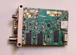
P5SAT100C3
Apr 05, 2004Microwave Video and Audio Transmitter
Equipment Class
TNB - Licensed Non-Broadcast Station Transmitter