P68STB28821818Bluetooth Wireless Stereo Headphones
Audex Telecom Industrial Co. Ltd.
Click to zoom
Application Details
- Equipment Class
- DSS - Part 15 Spread Spectrum Transmitter
- Date of Grant
- Dec 21, 2006
- Application Purpose
- Original Equipment
- Date of Application
- Dec 21, 2006
- Equipment Note
- Bluetooth Wireless Stereo Headphones
- Frequency Range
- 2402.00000000 - 2480.00000000
- Country
- China
Documents & Files
Document Text
Text extracted from the exhibit documents filed with the FCC. Open a document above to read the original.
Users Manual
Designed/Manufactured by Telecom Industrial Co., LTD. Http://www.celleden.com E-mail: [email protected] User’s Guide Bluetooth Accessories | STB-2882 Wireless Stereo Headphones Index (EN) 1 Index 1 Overview Welcome Operating Instructions -- demonstration -- power on/off -- pairing -- volume adjustment -- playing stereo music -- answering/ending phone calls -- control overview -- low-power prompt Package contents Important information Specifications Conformity Declaration 3 4 5 - 12 5 10 6 7 8 9 9 10,11 17 2 13,14 16 ® -- pairing with other Bluetooth devices 12 The accessories may be subject to change for the sake of product improvement. Changes may be made without prior notice. Main unit User's Guide U s e r' s g u id e USB Extension Cable Package Contents (EN) 2 Quick Guide -- charging 6 Replacement ear buds Glossary 15 Functional Parts (EN) 3 MFB * Back DC jack LED indicator Vol Vol Front Rear Forward Earphone Microphone Bottom * Multi-function button: Power/Pairing/Talk/Reject/Play, etc. 4 Welcome (EN) Wearing the STB-2882 Thank you for your purchase of our STB-2882 Portable . This User's Guide will help you to learn the basic features. Please read it carefully before using. You will find the STB-2882 to be convenient, compact and easy to use. It’s both a handsfree headset and a pair of wireless stereo headphones, perfect for all your favorite music files. Please note that your Bluetooth music source must be able to transmit A2DP stereo - if not, you may need an accessory audio adapter. If you’re not familiar with some of the technical terms in this Guide, please consult the glossary on page 15. Stereo Headphones ® Charging Use the USB cable included in the package to connect the STB-2882 with any USB port. Charging will start automatically when the STB-2882 is connected and the red indicator light will turn on. It will then turn off when charging is completed. Note: Make sure you charge the unit for at least 3 hours before first use. Power on/off Press and hold the MFB for about 4 seconds to turn on, and two seconds to turn off. When the STB-2882 is turned on it will be in Standby mode. Please note that the STB-2882 needs to be paired with another Bluetooth source before it can transmit voice or music. See the next section. ® Operating Instructions (EN) 6 about 4 seconds 5 Operating Instructions (EN) ® Bluetooth mobile phone ® Bluetooth enabled PDA ® USB Bluetooth Stereo Dongle ® Bluetooth Audio Adapter Demonstration 1 2 3 4 5 6 7 8 9 0 * # Pairing "Pairing" means creating a trusted relationship between ® two or more Bluetooth devices. The devices must be paired before they can communicate with each other. Pairing identification is stored for later use, and the devices will automatically recognize each other the next time they are connected. The STB-2882 will store up to 7 device IDs in memory, although it can only connect to one device at a time. Note: Make sure the STB-2882 is “off” before starting the Pairing procedure. How to pair with cellphones 1. Place the STB-2882 within 30 cm of the device to be paired with. Operating Instructions (EN) 7 <30cm> about 6 seconds Volume adjustment At any time during a phone call, or while playing music, the volume can be changed with the Vol+ or Vol- keys. There will be a tone from the speakers to indicate that the level has changed, and there will be a separate tone when at max. or min. volume. 2. Press and hold the MFB for about 6 seconds, until the red and blue LEDs flash alternately. The STB-2882 will now be in Pairing mode. ® 3. Initiate the Bluetooth search function in the cellphone. Please refer to the user's manual of the cellphone for more information. 4. Select “STB-2882” in the device list on the phone and follow the instructions to proceed. 5. Follow the instruction to enter the pairing code “1234”. The red LED indicator will stop flashing if pairing is successful. The STB-2882’s device ID will be stored in the device list of the phone so that no pairing will be required for the next use. Operating Instructions (EN) 8 Code: 1234 1 2 3 4 5 6 7 8 9 0 * #
Users Manual
Volume down Volume up Operating Instructions (EN) 9 Stereo Music ® After pairing with a Bluetooth device that supports the A2DP profile, such as a PC or a cellphone, the music output of those devices will be transmitted to the STB-2882 and the music play can be controlled from the STB-2882 (please refer to the attached control overview). Answering/Ending phone calls If you are playing music from the cellphone, the music play will be paused when there is an incoming call. A beep tone will also be heard to notify that there is an incoming call. Press the multi-function button once to answer the call and press it once again to end the call. When the call is ended, the music play will be automatically resumed. Low-power prompt The red LED will flash and a beep sound will be heard from the unit when the power level is low. Please recharge the unit. Operating Instructions (EN) 10 Status TALK Vol+ Vol- Press and hold Press briefly Power on (around 4 secs) Enter pairing mode (around 6 secs) Power Off No function No function No function No function No function Standby Last number redial Last number redial Vol+Vol- Voice activated dial Power off (around 2 secs) Cancel pairing Pairing Power off No function No function No function No function Cancel Voice Activated Dial Voice Activated Dial Power off No function No function No function No function Reject call Answer call Incoming call No function No function No function No function During a call End call Power off Volume up Mute Volume Down Mute Press and hold Press briefly Press and hold Press briefly Control overview The voice activated dialing function only works with cellphones that support this function. Some cellphones may not support some or all of the above functions. Please refer to the user’s manual of your cellphone for more information. Operating Instructions (EN) 12 Pairing with other Bluetooth devices ® ® a. Pairing with a Bluetooth enabled PDA 1. Refer to the pairing procedure (1 & 2) shown on page 7. ® 2. Initiate the Bluetooth search function on the PDA. Please refer to the user's manual of the PDA for more information. 3. Select “STB-2882” in the device list on the PDA and follow the instructions to proceed. The pairing code is “1234”. ® b. Pairing with a Bluetooth Dongle (works with PCs or laptops) 1. Refer to the pairing procedure (1 & 2) shown on page 7. ® 2. Initiate the Bluetooth search function on the PC or laptop. Please refer to the user's manual of the dongle for more information. 3. Select “STB-2882” in the device list on the PC or laptop and follow the instructions to proceed. The pairing code is “1234”. ® c. Pairing with a Bluetooth Audio Adapter (the Celleden STB-3131 and STB-381 are strongly recommended) 1. Refer to the pairing procedure (1 & 2) shown on page 7. ® 2. Initiate the paring function of the Bluetooth audio adapter. Please refer to the user's manual of the adapter for more information. 3. The red LED indicator on STB-2882 will stop flashing when pairing is successful. 11 Status Talk Vol Vol Vol N/AN/A Play N/AN/A Standby Pause N/AN/A Back N/A N/A N/A N/A N/A N/A The functions below only apply to devices supporting the A2DP / AVRCP profile. Consult the user's manual for more information. Here is the control overview for playing stereo music. Press and hold Press briefly Press and hold Press briefly Press and hold Press briefly Press and hold Press briefly Press and hold Press briefly Play Power off Power off Power off Pause Play Vol Vol Vol- Vol- Vol- Forward Previous song Previous song Previous song Next song Next song Next song Operating Instructions (EN) Control overview Play Standby Pause Status (Note: Please read all this information before ® using the STB-2882 Bluetooth Stereo Headphones) 1. Check for any exceptions or rules, due to national/local requirements or limitations, in usage ® of these Bluetooth Stereo Headphones or any other ® Bluetooth devices. 2. Please note that only authorized Celleden dealers or service partners should remove and/or replace the rechargeable battery, or any other components. 3. Please use Celleden original accessories only. Use of non-Celleden original accessories may result in damage, loss of performance to the headphones, injury, electric shock or even fire. 4. Please do not expose the Stereo Headphones to extreme high or low temperatures, moisture or fluid. 5. Please do not drop, throw or bend the Stereo Headphones as rough treatment will damage them . 6. If the Stereo Headphones will not be used for a while, please store them in a place where it is dry, free from dust, and not prone to extreme temperature fluctuations. 7. RF frequency and energy may affect some electronic systems in a motor vehicle. Please check with the manufacturer to ensure that the headphones will not affect the electronic systems in the motor vehicle. Important Information (EN) 13 Important Information (EN) 14 8. Some medical electronic equipment may not be shielded from R F energy.T herefore, please do not use the headphones near medical equipment without permission. 9. Please turn off the Stereo Headphones before boarding any aircraft. To prevent any interference with communication systems, please do not use the Stereo Headphones while the plane is in the air. 10.Please turn off the Stereo Headphones in any area with a potentially explosive atmosphere. 11.Please do not allow children to play with the Stereo Headphones since it contains small parts. 12.Please do not expose the rechargeable battery to extreme temperatures. If the battery is used at low temperature , the battery capacity will be reduced. Technical Specifications ® Compliance: Bluetooth version 1.2 Class 2 6 ~ 4 dBm Frequency range: 2.4-2.48 GHz Speaker output: < 100 dB Talk time: about 5 hours Note: The Stereo Headphones are connected to a mobile phone or other electronic device using radio frequency signals which cannot guarantee connection under all conditions or circumstances. Therefore, please never rely solely upon the headp…
Text truncated - open the document above for the full version.
External Photos
External Photos EUT- Full View EUT- Front View EUT- Back View (1) EUT- Back View (2)
ID Label/Location Info
ID Label FCC Label FCC ID: P68STB28821818
ID Label/Location Info
ID Label/Location Label Location Information Specifications : Text is Black or white in color and is left justified. Labels are printed in indelible ink on permanent adhesive backing or silk-screened onto the EUT or shall be affixed at a conspicuous location on the EUT. Refer to the below arrow.
Internal Photos
Internal Photos EUT- Inside View (1) EUT- Inside View (2) EUT- Main PCB Top View EUT- Main PCB Bottom View EUT- PCB 1 Top View EUT- PCB 1 Rear View EUT- PCB 2 Top View EUT- PCB 2 Rear View
Operational Description
STB-2882 Bluetooth stereo headset Operating Elements 1. Power supply: Used 3.7V lithium ion battery (Size 4x20x23mm) 2. Charger circuit : DC_JACK,U3,C11,C15,R2,C20 and BAT compose the charger circuit . When you link the DC_JACK with a PC USB port,U3 start working , control the charger current and time , until the battery is full. 3. C5,U4,L7,C18,C3,U2,R21,R1,C33,C21,C17,C24 compose the power control circuit. U2 can output 3.3V power,U4 can output 1.8V power, supply the U1 and other circuit to work. 4. SW1,R6,R3,C14,R5 and D2 compose the ON/OFF circuit, pushing SW1 can startup the U2,U4 and U1.VOL+,VOL-,R10,R12 compose the Volume cortral circuit. 5. Speaker circuit: L3,L4,C10,C9,SPK1,SPK2,L1,L5,C1 and C2 compose the speaker circuit. 6. R8,R9,R19,Q3,D5 and D3 compose the indicator light circuit. 7. ANT1,C32,C31 and L2 compose the antenna circuit. 8. U1,R33,R34,C2,R4,C13 and R7 compose the Bluetooth module circuit . 9. Microphone circuit: R11,Q2,C12,R17,C7,C8,C6,C16,L6,C50, and MIC1 compose the microphone circuit.
Operational Description
Hopping Information 1 Hopping Range Hereby we declare that the maximum frequency of this device is: 2402-2480MHz. This is according the Bluetooth Core Specification V1.2 (+ critical errata) for devices which will be operated in the USA. This was checked during the Bluetooth Qualification tests (Test Case: TRM/CA/04-E). Other frequency ranges (e.g. for Spain, France, Japan) which are allowed according the Core Specification are not supported by this device. 2 Hopping Sequence Example of a 79 hopping sequence in data mode: 33,04,21,44,23,42,53,46,55,48,40,59,72,29,76,31,08,73, 07,75,09,45,60,39,58,13,47,11,77,52,35,50,65,54,67,56, 69,62,71,64, 37,25,27,66,57,70,74,61,78,63,10,41,05,43, 15,44,64,68,02,70,06,01,51,03,55,05,03,66,53,49,36,47, 3 Receiver input bandwidth The input bandwidth of the receiver is 1MHz. In every connection one Bluetooth device is the master and the other one is the slave. The master determines the hopping sequence. The slave follows this sequence. Both devices shift between RX and TX time slot according to the clock of the master. Additionally the type of connection is set up at the beginning of the connection. The master adapts its hopping frequency and its TX/RX timing according to the packet type of the connection. Also the slave of the connection will use these settings. Repeating of a packer has no influence on the hopping sequence. The hopping sequence generated by the master of the connection will be followed in any case. That means a repeated packet will not be send on the same frequency, it is send on the next frequency of the hopping sequence.
RF Exposure Info
Since the output power was so low, it met the RF exposure requirement.
Test Report
Note: This test report is for the customer shown above and their specific product only. It may not be duplicated or used in part without prior written consent from Bay Area Compliance Laboratory Corp. (Shenzhen). This report must not be used by the customer to claim product certification, approval, or endorsement by NVLAP, NIST or any agency of the U.S. Government. FCC PART 15.247 EMI MEASUREMENT AND TEST REPORT For Audex Telecom Industrial Co., Ltd. 4/F., Chuangye Center, Kangle Rd., Zhongshan Torch Hi-Tech Industrial Zone, Zhongshan, Guangdong, China FCC ID: P68STB28821818 This Report Concerns: Original Report Equipment Type: Bluetooth Wireless Stereo Headphones Test Engineer: Merry Zhao Report No.: RSZ06112301 Test Date: 2006-12-08 to 2006-12-13 Report Date: 2006-12-19 Reviewed By: EMC Manager: Boni Baniqued Prepared By: Bay Area Compliance Laboratory Corp. (Shenzhen) 6/F, the 3rd Phase of WanLi Industrial Building, ShiHua Road, FuTian Free Trade Zone, ShenZhen, Guangdong 518038, P.R.China Tel: +86-755-33320018 Fax: +86-755-33320008 Audex Telecom Industrial Co., Ltd. FCC ID: P68STB28821818 Report # RSZ06112301 Page 2 of 47 FCC Part 15.247 Test Report TABLE OF CONTENTS GENERAL INFORMATION.......................................................................................................................................4 PRODUCT DESCRIPTION FOR EQUIPMENT UNDER TEST (EUT) ....................................................................................4 OBJECTIVE...................................................................................................................................................................4 RELATED SUBMITTAL(S)/GRANT(S).............................................................................................................................4 TEST METHODOLOGY..................................................................................................................................................4 TEST FACILITY.............................................................................................................................................................4 HOST SYSTEM CONFIGURATION LIST AND DETAILS....................................................................................................5 LOCAL SUPPORT EQUIPMENT LIST AND DETAILS........................................................................................................5 EXTERNAL I/O CABLE..................................................................................................................................................5 SYSTEM TEST CONFIGURATION ..........................................................................................................................6 DESCRIPTION OF TEST CONFIGURATION......................................................................................................................6 EUT EXERCISE SOFTWARE..........................................................................................................................................6 SPECIAL ACCESSORIES.................................................................................................................................................6 EQUIPMENT MODIFICATIONS.......................................................................................................................................6 CONFIGURATION OF TEST SETUP.................................................................................................................................7 BLOCK DIAGRAM OF TEST SETUP................................................................................................................................8 SUMMARY OF TEST RESULTS ...............................................................................................................................9 §15.247(b) - RF EXPOSURE ......................................................................................................................................10 LIMIT.........................................................................................................................................................................10 §15.203 - ANTENNA REQUIREMENT....................................................................................................................11 STANDARD APPLICABLE............................................................................................................................................11 ANTENNA CONNECTOR CONSTRUCTION....................................................................................................................11 §15.107 (a) - CONDUCTED EMISSION...................................................................................................................12 MEASUREMENT UNCERTAINTY..................................................................................................................................12 EUT SETUP................................................................................................................................................................12 EMI TEST RECEIVER SETUP.......................................................................................................................................13 TEST EQUIPMENT LIST AND DETAILS.........................................................................................................................13 TEST PROCEDURE......................................................................................................................................................13 TEST RESULTS SUMMARY..........................................................................................................................................13 TEST DATA................................................................................................................................................................14 PLOT(S) OF TEST DATA.........................…
Text truncated - open the document above for the full version.
Test Setup Photos
Test Setup Photos Charging Mode: Conducted Emission - Front View Charging Mode: Conducted Emission - Rear View Transmitting Mode: Radiated Emission - Front View (30-1000MHz) Transmitting Mode: Radiated Emission - Rear View (30-1000MHz) Transmitting Mode: Radiated Emission - Front View (Above 1GHz) Transmitting Mode: Radiated Emission – Rear View (Above 1GHz) Charging Mode: Radiated Emission
Contact Information
Applicant
Marion Z.(R&D Manager)
Test Firm
Bay Area Compliance Laboratory Corp. (Shenzhen)John Chan
Technical Specifications
| # | Rule Parts | Frequency Range | Power Output |
|---|---|---|---|
| 1 | 15C | 2.40 GHz - 2.48 GHz | 152.00 µW |
Other Applications from Audex Telecom Industrial Co. Ltd.
P68MT7000
Mar 24, 2010Motor Trend Bluetooth Headset
Equipment Class
DSS - Part 15 Spread Spectrum TransmitterP68B00788
Dec 21, 2008FM Transmitter
Equipment Class
DXX - Part 15 Low Power Communication Device Transmitter
P68ADB23881898
Jul 23, 2007Bluetooth Micro Headset
Equipment Class
DSS - Part 15 Spread Spectrum Transmitter
P68SPB28022F88
Aug 30, 2006LCD Speakerphone
Equipment Class
DSS - Part 15 Spread Spectrum Transmitter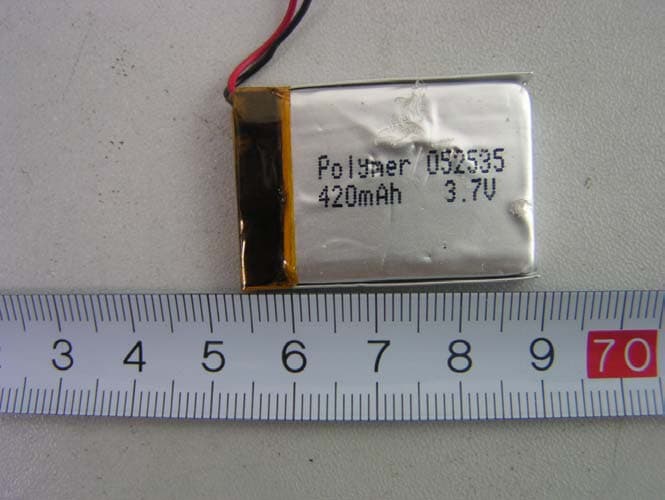
P68STB31311398
Jul 12, 2006Universal Stereo Dongle
Equipment Class
DSS - Part 15 Spread Spectrum Transmitter