P6F2001C04Scorpion 1M Tags
RF Code, Inc.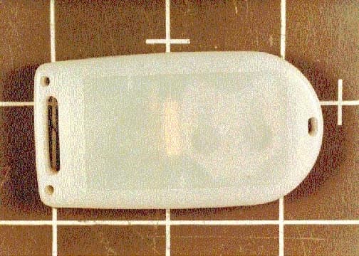
Click to zoom
Application Details
- Equipment Class
- DSC - Part 15 Security/Remote Control Transmitter
- Date of Grant
- Feb 19, 2002
- Application Purpose
- Original Equipment
- Date of Application
- Feb 19, 2002
- Equipment Note
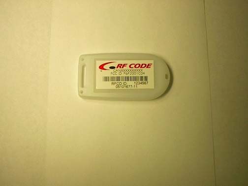
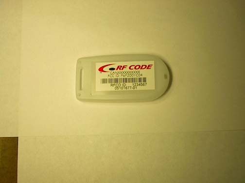
- Scorpion 1M Tags
- Frequency Range
- 303.91500000 - 303.91500000
- Company
- RF Code, Inc.
- Country
- United States
Documents & Files
Document Text
Text extracted from the exhibit documents filed with the FCC. Open a document above to read the original.
Users Manual
Scorpion I Reader User’s Guide RF Code, Inc. Publication: 03801674-01 Issue DateCommentRevision November 8, 2001Initial Release00 January 23, 2002Added P/N’s of added equipment01 February 6, 2002Added FCC Disclaimer and Motion tag P/N detail02 is the trademark of RF Code, Inc. 1250 South Clearview Ave. Mesa, AZ 85208 (480) 969-2828 www.rfcode.com Copyright 2001 RF Code, Inc. All Rights Reserved Scorpion I Reader II Copyright 2001 RF Code, Inc. FCC Certification Information to User: - Changes or modifications to this equipment, not expressly approved by the party responsible for compliance could void the user’s authority to operate the equipment. Note: This equipment has been tested and found to comply with the limits for a Class B digital device, pursuant to part 15 of the FCC rules. These limits are designed to provide reasonable protection against harmful interference when the equipment is operated in a residential installation. This equipment generates, uses and can radiate radio frequency energy and, if not installed and used in accordance with the instructions, may cause harmful interference to radio communications. However there I no guarantee that interference to radio or television reception, which may be determined by turning the equipment off and on, the user is encourged to try to correct the interference by one or more or the following measures: ! Reorient or relocate the receiving antenna. ! Increase the separation between the equipment and receiver. ! Connect the equipment into an outlet on a circuit different from that to which the receiver is connected. ! Consult the dealer or an experienced radio/TV technician for help. Operation of this equipment in a residential area is likely to cause harmful interference in which case the user will be required to correct the interference at his own expense. The Scorpion I’s two major components are independently certified and comply with Federal Communications Commission (FCC) rules, part 15. 1. This Scorpion I Reader complies with part 15 of the FCC rules. Operation is subject to the following two conditions: (1) this device may not cause harmful interference, and (2) this device must accept any interference received, including interference that may cause undesired operation. 2. The system operates by using Scorpion I tags that have been certified or are in the certification process. These devices comply with part 15 of the FCC rules. Operation is subject to the following two conditions: (1) these devices may not cause harmful interference, and (2) these devices must accept any interference received, including interference that may cause undesired operation. a. FCC ID: N3S2001B01 for: i. Standard 7 second Spider Tag P/N: 05101297-06. Scorpion I Reader Copyright 2001 RF Code, Inc. III b. FCC ID: N3S2001B02 for: i. 13 second Spider Tag P/N: 05101297-07 ii. 25 second Spider Tag P/N: 05101297-20 iii. 50 second Spider Tag P/N: 05101297-21. c. FCC ID: P6F2001B03 for: i. 2 second Scorpion I Tag P/N: 05101297-26 ii. 5 second Scorpion I Tag P/N: 05101297-27 iii. 10 second Scorpion I Tag P/N: 05101297-28 iv. 15 second Scorpion I Tag P/N: 05101297-29. d. FCC IDs: P6F2001C04 for: i. Scorpion I Tags with motion sensor P/N 05101677-01 (containing PCB level P/N 02021663-01) ii. Scorpion I Tags W/O motion sensor P/N 05101677-11 (containing PCB level P/N 02021663-11) Scorpion I Reader IV Copyright 2001 RF Code, Inc. Table of Contents 1INTRODUCTION.............................................................................................................. 1 2PURPOSE............................................................................................................................ 1 3SCOPE................................................................................................................................. 1 4SCORPION I READER..................................................................................................... 2 4.1S CORPION I R EADER P HYSIC AL I/O............................................................................... 2 4.2S CORPION I R EADER I NT ERNAL S ETTINGS ..................................................................... 5 4.3S CORPION I R EADER A NTENNAS ................................................................................... 7 4.4S CORPION I R EADER E NVIRONMENTAL L IMITS ............................................................. 8 4.5S CORPION I R EADER M OUNTING ................................................................................... 8 4.6S CORPION T AGS ............................................................................................................. 9 List of Figures Figure 1 Scorpion I Reader (Front View) ..........................................................................2 Figure 2 Scorpion I (Rear View) .....................................................................................3 Figure 3 Scorpion I Internal Configuration Points ..............................................................5 Figure 4 Scorpion I Physical Mounting Dimensions ...........................................................9 Scorpion I Reader Copyright 2001 RF Code, Inc. 1 1 Introduction The RF Code Scorpion I System is an RFID monitoring system designed to report tags within defined reader operating ranges. The system utilizes “beacon” tags that periodically report their presence with an encoded radio transmission. The Scorpion I Reader is a dual channel radio receiver tuned to the Scorpion I Tag transmission frequency. The Scorpion I includes a Client Bridge as the interface between the Scorpion I Reader and an Ethernet network. The reader receives the message and decodes the tag’s identity each time the tag transmits. The reader sends the tag identity information through the Client Bridge to the RF Code Concentrator LI software application for processing. The Client Bridge can be configured to operate as a wired connection to the Ethernet 10/100 netwo…
Text truncated - open the document above for the full version.
Cover Letter(s)
1250 S. Clearview Avenue, Mesa, AZ 85208-3378, Phone: (480) 969-2828, Fax: (480) 325-4029 January 22, 2001 Federal Communications Commission 7435 Oakland Mills Road, Columbia, MD 21046 Gentlemen: This letter is to comply with Section 0.457(d)(i) pertaining to confidential material. RF Code, Inc. would like the following documents regarding this submission for FCC ID P6F2001C04 to be kept confidential. 1. Circuit Schematic Diagram 2. Spider Tag Block Diagram The above material contains trade secrets or technical data, which would customarily be guarded from competitors. We do not want these documents to be accessible to the general public. Signed: Kevin Hanson, Chief Financial Officer, RF Code, Inc.
Operational Description
SCORPION I TAG OPERATING DESCRIPTION The Scorpion I Tag consists of a SAW controlled 303.825 MHz oscillator that includes a thin film single loop inductor that serves as the radiating element. This oscillator is operated in a Keyed –On-Off (KOO) under the instruction of a microprocessor. The microprocessor is programmed to turn the oscillator on periodically and transmit the Tag’s unique code in a series of short pulses, before shutting down. The Tag may also have installed a mechanical motion-sensing switch that can initiate an immediate group of code transmissions before returning to its normal mode. The two Tags are identical in every respect (in terms of both hardware and firmware) except as to whether the motion sensor is installed. The tag can operate in the operator initiated (manual) mode of operation or in a self- activation (automatic) mode of operation but not both at the same time. In manual operation, under FCC 15-231, the tag is activated by a switch when an operator or user picks up or moves the tag from one location to another with each individual activation resulting in a transmission having a unique code. When the manual activation is over the tag shuts off within 5 seconds, and for a time greater than 10 seconds, before returning to the default self-activation mode. In the self-activated mode of operation, under FCC 15- 231, the tag outputs with another unique code at a period that is longer than 10 seconds or 30 times the transmission period between transmissions. If no motion sensor is installed his later mode of operation is the Tag’s only mode of operation. The transmission Pulse width is 40 microseconds, the number of pulses per transmission is 61 (randomly spaced) and the period over which these pulse transmissions occurs is 130 milliseconds. The tag then returns to its sleep mode until it is time to beacon again.
Test Report
Page 1 of 41 Report No.: FC02-009A ADDENDUM TEST REPORT TO FC02-009 FOR THE SCORPION 1M TAGS, MODELS 05101677-01 & 05101677-11 FCC PART 15 SUBPART C SECTION 15.231 COMPLIANCE DATE OF ISSUE: FEBRUARY 13, 2002 PREPARED FOR: RF Code, Inc. 1250 S. Clearview, Suite 104 Mesa, AZ 85208 PREPARED BY: Mary Ellen Clayton CKC Laboratories, Inc. 5473A Clouds Rest Mariposa, CA 95338 P.O. No.: 201-3230 W.O. No.: 78016 Date of test: December 13, 2001 through February 11, 2002 Report No.: FC02-009A This report contains a total of 41 pages and may be reproduced in full only. Partial reproduction may only be done with the written consent of CKC Laboratories, Inc. Page 2 of 41 Report No.: FC02-009A TABLE OF CONTENTS Administrative Information ............................................................................................. 4 Summary of Results......................................................................................................... 5 Conditions for Compliance.............................................................................................. 5 Approvals......................................................................................................................... 5 Equipment Under Test (EUT) Description...................................................................... 6 Transmitter Characteristics.............................................................................................. 6 EUT Operating Frequency................................................................................... 6 15.31(e) Voltage Variation .................................................................................. 6 15.31(m) Number of Channels ............................................................................ 6 15.33(a) Frequency Ranges Tested ..................................................................... 6 15.203 Antenna Requirements ............................................................................ 6 15.205 Restricted Bands ...................................................................................... 7 Equipment Under Test..................................................................................................... 7 Peripheral Devices ........................................................................................................... 7 Temperature and Humidity During Testing .................................................................... 7 Report of Measurements.................................................................................................. 8 Table 1:Dynamic: 15.231(b) Peak Power Output ............................................... 8 Table 2:Dynamic:15.209 Highest Radiated Emission Levels: 9kHz-30MHz..... 9 Table 3:Dynamic: 15.231(b) Highest & Spurious: 30-1000MHz ....................... 10 Table 4:Dynamic: 15.231(b) Highest Spurious Emission Levels: 1-4GHz ........ 11 Table 5:Static: 15.231(e) Peak Power Output ..................................................... 12 Table 6:Static: 15.209 Highest Radiated Emission Levels: 9kHz-30MHz ......... 13 Table 7:Static: 15.231(e) Highest Spurious: 30-1000MHz ................................. 14 Table 8:Static: 15.231(e) Highest Spurious Emission Levels: 1-4GHz .............. 15 Measurement Uncertainty................................................................................................ 16 EUT Setup .......................................................................................................................16 Correction Factors ........................................................................................................... 16 Table A: Sample Calculations ............................................................................. 16 Test Instrumentation and Analyzer Settings.................................................................... 17 Table B: 15.35 Analyzer Bandwidth Settings Per Frequency Range.................. 17 Spectrum Analyzer Detector Functions............................................................... 17 Peak ......................................................................................................... 17 Quasi-Peak............................................................................................... 18 Average.................................................................................................... 18 EUT Testing ....................................................................................................................18 Radiated Emissions ............................................................................................. 18 Appendix A: Test Setup Photographs ............................................................................. 20 Photograph Showing Radiated Emissions ........................................................... 21 Photograph Showing Radiated Emissions ........................................................... 22 Appendix B: Test Equipment List ................................................................................... 23 Page 3 of 41 Report No.: FC02-009A Appendix C: Measurement Data Sheets .......................................................................... 24 15.231(c) Occupied Bandwidth Plot ................................................................... 25 15.231(c) Occupied Bandwidth Plot ................................................................... 26 15.231(e) Timing Plot.......................................................................................... 27 Pulse Duration In Alarm Mode ........................................................................... 28 Pulse Duration In Standby Mode......................................................................... 29 Dynamic: 15.231(b) Peak Power Output............................................................. 30 Dynamic: 15.209 ................................................................................................. 31 …
Text truncated - open the document above for the full version.
Test Setup Photos
PHOTOGRAPH SHOWING RADIATED EMISSIONS Radiated Emissions - Front View PHOTOGRAPH SHOWING RADIATED EMISSIONS Radiated Emissions - Back View
Contact Information
Applicant
Jonathan Guy(VP Engineering)
Technical Contact
CKC Laboratories, inc.Joyce Walker
[email protected]1-800-500-4362
5473A Clouds Rest · Mariposa, California · United States
Non-Technical Contact
CKC Laboratories, Inc.Joyce Walker
[email protected]1-800-500-4362
Test Firm
CKC Laboratories, Inc.Steve Behm
Technical Specifications
| # | Rule Parts | Frequency Range | Power Output |
|---|---|---|---|
| 1 | 15.231 | 303.915 MHz - 303.915 MHz | - |
Other Applications from RF Code, Inc.
P6FM190
Jun 02, 2026M190 IR Enabled IT Asset Tag
Equipment Class
DSC - Part 15 Security/Remote Control Transmitter
P6F-MAT433
Jan 16, 2020Mobile Asset Tag
Equipment Class
DSC - Part 15 Security/Remote Control Transmitter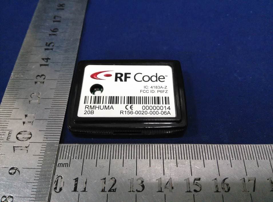
P6FZ
Apr 20, 2015Humidity-Temperature Tag
Equipment Class
DSC - Part 15 Security/Remote Control Transmitter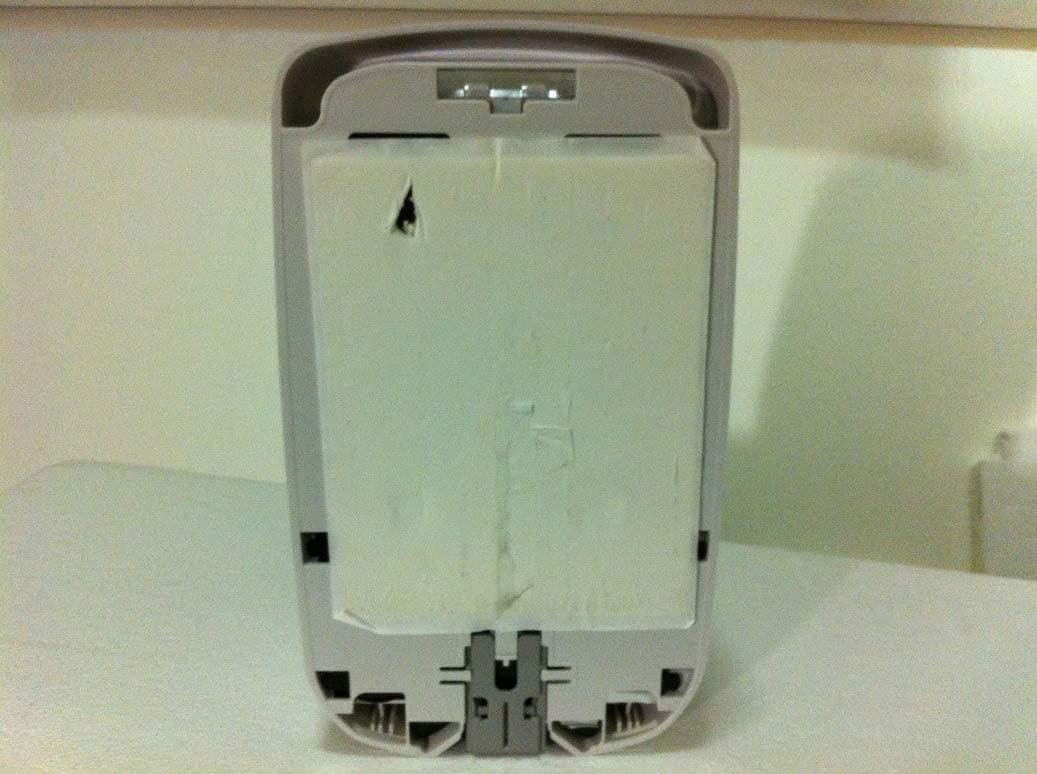
P6F4LTX
Jul 16, 2014Asset Tracking and Event Transmitter
Equipment Class
DTS - Digital Transmission SystemP6F4TFX
Nov 02, 2013Asset Tracking and Event TX
Equipment Class
DTS - Digital Transmission System