P6F2005303Mantis II RFID Tag 303 MHz
RF Code, Inc.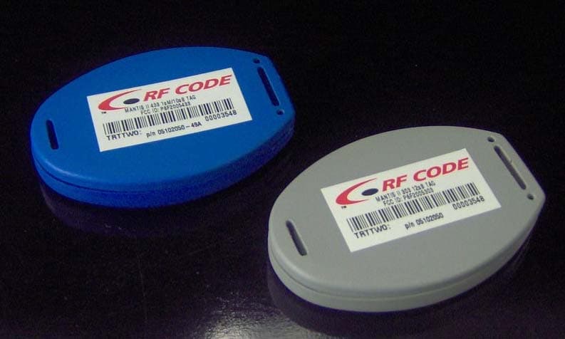
Click to zoom
Application Details
- Equipment Class
- DSC - Part 15 Security/Remote Control Transmitter
- Date of Grant
- Apr 13, 2006
- Application Purpose
- Original Equipment
- Date of Application
- Apr 12, 2006
- Equipment Note
- Mantis II RFID Tag 303 MHz
- Frequency Range
- 303.82500000 - 303.82500000
- Company
- RF Code, Inc.
- Country
- United States
Documents & Files
Document Text
Text extracted from the exhibit documents filed with the FCC. Open a document above to read the original.
Users Manual
Mantis™ II Reader User Manual Revision 05 © Copyright 2003-2005 RF Code, Inc. All rights reserved. UM-C2020-R05-20030422. No copying of this material is allowed without prior written permission. Page 2 of 28. USER MANUAL – Mantis™ II Reader 2 User Manual Document Created: 22 April 2003 Document ID: UM-C2020-R05-20030422 Issue Date Comment Revision 22 Apr 2003 Initial Draft 00 02 Oct 2003 Revision 01 15 Dec 2003 Revision - Reformatted into new design. New cover. 24 pgs. 02 24 Jun 2004 Revision – Updated programmer utility information. 24 pgs. 03 16 Dec 2004 Revision – Updated programmer utility information. 24 pgs. 04 13 May 2005 Revision – Various updates. 28 pgs. 05 Important - This document is not intended for public distribution. No copying of this material is allowed without prior written permission. © Copyright 2003-2005 RF Code, Inc. All rights reserved. UM-C2020-R05-20030422. No copying of this material is allowed without prior written permission. Page 3 of 28. USER MANUAL – Mantis™ II Reader 3 Contents User Manual 1. Introduction........................................................................5 2. Hardware ............................................................................6 Front View – LED Indicators ................................................... 6 Rear View – Data Connections................................................ 7 Antennas – Positioning .......................................................... 8 Environmental Limits ...........................................................10 Tag Positioning ...................................................................10 3. Firmware ..........................................................................11 File System ........................................................................11 Upgradeable Firmware .........................................................11 Reader Setup......................................................................12 Launch Utility.......................................................................12 Reader Settings ....................................................................14 Network Settings ..................................................................15 Advanced Network Settings ....................................................16 Programming Options ............................................................17 Network Installation ..............................................................18 Configuration Files & Default Settings.....................................18 4. Troubleshooting................................................................21 Appendix A. List of Acronyms ...............................................................24 B. Index ................................................................................26 C. FCC Compliance ................................................................27 D. Copyright Statement .........................................................28 © Copyright 2003-2005 RF Code, Inc. All rights reserved. UM-C2020-R05-20030422. No copying of this material is allowed without prior written permission. Page 4 of 28. 4 USER MANUAL – Mantis™ II Reader User Manual 1 – Introduction 2 – Hardware 3 – Firmware 4 – Troubleshooting © Copyright 2003-2005 RF Code, Inc. All rights reserved. UM-C2020-R05-20030422. No copying of this material is allowed without prior written permission. Page 5 of 28. 5 USER MANUAL – Mantis™ II Reader 1 – Introduction The Mantis™ II System by RF Code is an RFID monitoring system designed to report Tags within defined Reader operating ranges. The system utilizes “beacon” Tags that periodically report their presence with an encoded radio transmission. The Mantis™ II Reader is a dual-channel radio receiver tuned to the Mantis™ Tag transmission frequency of 303.825 MHz. This manual provides the instructions for the Mantis™ II Reader setup and operation. This Reader has different modes of operation and optional functions that are user-selected depending on the system’s operational requirements. The instructions in this manual show how to install, configure, and upgrade the Mantis™ II Reader as well as tips on Mantis™ Tag placement and antenna optimization. Operational instructions for the Mantis™ II System using the TAVIS™ Concentrator software by RF Code are found in the TAVIS™ Concentrator user manual. © Copyright 2003-2005 RF Code, Inc. All rights reserved. UM-C2020-R05-20030422. No copying of this material is allowed without prior written permission. Page 6 of 28. 6 USER MANUAL – Mantis™ II Reader 2 – Hardware The Mantis™ II Reader is housed in a 5 x 5 x 1.5 inch (12.7 x 12.7 x 3.81 cm) metal chassis and contains the internal components of a RFID Reader combined with connections to allow for both Ethernet and serial port connectivity. Front View – LED Indicators Figure 2.1 – Mantis™ II Reader (front view) shown with standard ¼-wave helical antennas. Three LEDs are mounted on the front of the Mantis™ II Reader. • Unlabeled LED – This LED is used for a feature that is not implemented in this version of the Reader. • On-Ready LED – This LED indicates that the Reader has power applied through an external power adapter. • Tag Activity LED – This LED is used for two purposes: (1) to show the status of the Reader while in standby mode and (2) to show Tag detections while in operation. © Copyright 2003-2005 RF Code, Inc. All rights reserved. UM-C2020-R05-20030422. No copying of this material is allowed without prior written permission. Page 7 of 28. 7 USER MANUAL – Mantis™ II Reader Tag Activity LED • While Operating – The Tag Activity LED flashes intermittently, indicating the Reader has read one or more Tags each time it flashes. Because the Reader can decode Tags faster than the light can be turned on and off, a single flash may indicate more than one Tag being decoded. • While in Standby Mode – The Tag Activity LED turns on and off at a distinctive rate that indicates the Reader…
Text truncated - open the document above for the full version.
Test Report
Test of Sign Post 303 To FCC 47 CFR Part 15.231 & IC RSS-210 Test Report Serial No; TUVR72-A2 REV C TEST REPORT FROM Test of Sign Post 303 To FCC 47 CFR Part15.231 & IC RSS-210 Test Report Serial No.: TUVR72-A2 Rev C This report supersedes TUVR72-A2 Rev B Manufacturer: RF Code Inc. 1250 S. Clearview Ave. Mesa, Arizona 85208 USA Product Function: RFID Tag Copy No:pdf Issue Date: 13th April '06 This Test Report is Issued Under the Authority of; MiCOM Labs, Inc. 3922 Valley Avenue, Suite B Pleasanton, California 94566, USA Phone: 925.462.0304 Fax: 925.462.0306 www.micomlabs.com MiCOM Labs is a UKAS (United Kingdom Accreditation Service) Accredited Testing Laboratory 2106 This test report may be reproduced in full only. The document may only be updated by MiCOM Labs personnel. Any changes will be noted in the Document History section of the report. Title: Sign Post 303 To: Serial #: Issue Date: Page: FCC 47 CFR Part15.231 & IC RSS-210 TUVR72-A2 Rev C 13th April '06 2 of 27 This test report may be reproduced in full only. The document may only be updated by MiCOM This page has been left intentionally blank Labs personnel. Any changes will be noted in the Document History section of the report. MiCOM Labs, 3922 Valley Avenue, Suite B, Pleasanton, CA 94566 USA, Phone: 925.462.0304, Fax: 925.462.0306, www.micomlabs.com Title: Sign Post 303 To: Serial #: Issue Date: Page: FCC 47 CFR Part15.231 & IC RSS-210 TUVR72-A2 Rev C 13th April '06 3 of 27 This test report may be reproduced in full only. The document may only be updated by MiCOM TABLE OF CONTENTS ACCREDITATION & LISTINGS.......................................................................................4 1. TEST RESULT CERTIFICATE.................................................................................7 2. REFERENCES AND MEASUREMENT UNCERTAINTY........................................8 2.1. Normative References............................................................................................8 2.2. Test and Uncertainty Procedures...........................................................................8 3. PRODUCT DETAILS AND TEST CONFIGURATIONS..........................................9 3.1. Technical Details....................................................................................................9 3.2. Scope of Test Program.........................................................................................10 3.3. Equipment Model(s) and Serial Number(s)..........................................................10 3.4. Antenna Details....................................................................................................10 3.5. Cabling and I/O Ports...........................................................................................11 3.6. Test Configurations...............................................................................................11 3.7. Equipment Modifications.......................................................................................11 3.8. Deviations from the Test Standard.......................................................................11 3.9. Subcontracted Testing or Third Party Data..........................................................11 4. TEST SUMMARY....................................................................................................12 5. TEST RESULTS......................................................................................................13 5.1. Device Characteristics..........................................................................................13 5.1.1. 20 dB Bandwidth.......................................................................................14 5.1.2. Field Strength Measurements...................................................................16 5.1.3. Duty Cycle.................................................................................................20 5.1.4. Restricted Bands.......................................................................................24 6. TEST SET-UP PHOTOGRAPHS............................................................................26 6.1. Field Strength Measurement................................................................................26 Labs personnel. Any changes will be noted in the Document History section of the report. MiCOM Labs, 3922 Valley Avenue, Suite B, Pleasanton, CA 94566 USA, Phone: 925.462.0304, Fax: 925.462.0306, www.micomlabs.com 7. TEST EQUIPMENT DETAILS.................................................................................27 Title: Sign Post 303 To: Serial #: Issue Date: Page: FCC 47 CFR Part15.231 & IC RSS-210 TUVR72-A2 Rev C 13th April '06 4 of 27 This test report may be reproduced in full only. The document may only be updated by MiCOM ACCREDITATION & LISTINGS MiCOM Labs, Inc. an accredited laboratory complies with the international standard BS EN ISO/IEC 17025. The company is accredited by the United Kingdom Accreditation Service (UKAS) www.ukas.org test laboratory number 2106. MiCOM Labs test schedule is available at the following URL; http://www.ukas.org/testing/lab_detail.asp?lab_id=875&location_id=&vMenuOption=3 . Labs personnel. Any changes will be noted in the Document History section of the report. MiCOM Labs, 3922 Valley Avenue, Suite B, Pleasanton, CA 94566 USA, Phone: 925.462.0304, Fax: 925.462.0306, www.micomlabs.com Title: Sign Post 303 To: Serial #: Issue Date: Page: FCC 47 CFR Part15.231 & IC RSS-210 TUVR72-A2 Rev C 13th April '06 5 of 27 This test report may be reproduced in full only. The document may only be updated by MiCOM LISTINGS MiCOM Labs test facilities are listed by the following organizations; North America United States of America Federal Communications Commission (FCC) Listing #: 102167 Canada Labs personnel. Any changes will be noted in the Document History section of the report. MiCOM Labs, 3922 Valley Avenue, Suite B, Pleasanton, CA 94566 USA, Phone: 925.462.0304, Fax: 925.462…
Text truncated - open the document above for the full version.
Contact Information
Applicant
Jonathan Guy(VP Engineering)
Technical Contact
RF Code, Inc.Dave Worthy
[email protected]480-969-2828
1250 S. Clearview Ave · Mesa, Arizona · United States
Non-Technical Contact
RF Code, Inc.Tim Geiger
[email protected]480-969-2828
Test Firm
MiCOM LabsGordon Hurst
Technical Specifications
| # | Rule Parts | Frequency Range | Power Output |
|---|---|---|---|
| 1 | 15.231,15.231(e) | 303.825 MHz - 303.825 MHz | - |
Other Applications from RF Code, Inc.
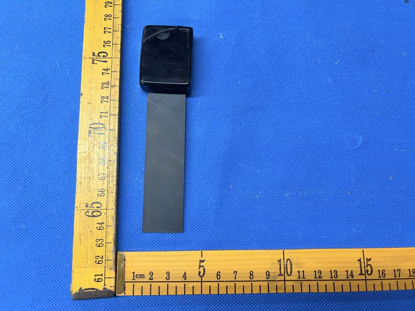
P6FM190
Jun 02, 2026M190 IR Enabled IT Asset Tag
Equipment Class
DSC - Part 15 Security/Remote Control Transmitter
P6F-MAT433
Jan 16, 2020Mobile Asset Tag
Equipment Class
DSC - Part 15 Security/Remote Control Transmitter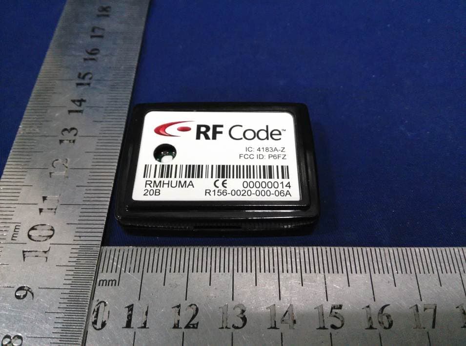
P6FZ
Apr 20, 2015Humidity-Temperature Tag
Equipment Class
DSC - Part 15 Security/Remote Control Transmitter
P6F4LTX
Jul 16, 2014Asset Tracking and Event Transmitter
Equipment Class
DTS - Digital Transmission SystemP6F4TFX
Nov 02, 2013Asset Tracking and Event TX
Equipment Class
DTS - Digital Transmission System