P6F433MHZRF Code Security Tag
RF Code, Inc.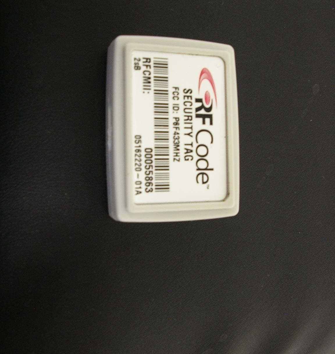
Click to zoom
Application Details
- Equipment Class
- DSC - Part 15 Security/Remote Control Transmitter
- Date of Grant
- Mar 25, 2007
- Application Purpose
- Original Equipment
- Date of Application
- Mar 25, 2007
- Equipment Note
- RF Code Security Tag
- Frequency Range
- 433.92000000 - 433.92000000
- Company
- RF Code, Inc.
- Country
- United States
Documents & Files
Document Text
Text extracted from the exhibit documents filed with the FCC. Open a document above to read the original.
Users Manual
Mantis™ II 433.92 MHz Reader User Manual Document Revision 1.02 UM-P2900-R101-20060404 © Copyright 2004-2006 RF Code, Inc. All rights reserved. UM-P2900-R101-20060404. No copying of this material is allowed without prior written permission. Page 2 of 24. 2 USER MANUAL – Mantis™ II 433.92 MHz Reader Contents 1. Introduction.........................................................................................................4 2. Hardware.............................................................................................................5 Front View – LED Indicators.................................................................................5 Rear View – Data Connections.............................................................................6 Antennas – Positioning.........................................................................................7 Environmental Limits.............................................................................................8 3. Firmware..............................................................................................................9 File System...........................................................................................................9 Upgradeable Firmware.........................................................................................9 Reader Setup......................................................................................................10 Reader Settings..................................................................................................11 Network Settings.................................................................................................12 Advanced Network Settings................................................................................13 Programming Options.........................................................................................14 Configuration Files & Default Settings................................................................15 4. Troubleshooting................................................................................................18 A. List of Acronyms...............................................................................................20 B. Index..................................................................................................................22 C. FCC Compliance...............................................................................................23 D. Copyright Statement.........................................................................................24 Document History Document Revised Document ID 04 April 2006 UM-P2900-R101-20060404 Issue Date Rev. Comment 26 Jul 2005 00 Initial Draft 21 Feb 2006 1.00 Revision – Design change and edits. 24 pgs. 04 Apr 2006 1.01 Minor edits and formatting changes. 24 pgs. 08 Mar 2007 1.02 Addition of new FCC designator L Note This document is not intended for public distribution. Copying of this material is not permitted without prior written permission. © Copyright 2004-2006 RF Code, Inc. All rights reserved. UM-P2900-R101-20060404. No copying of this material is allowed without prior written permission. Page 3 of 24. 3 USER MANUAL – Mantis™ II 433.92 MHz Reader © Copyright 2004-2006 RF Code, Inc. All rights reserved. UM-P2900-R101-20060404. No copying of this material is allowed without prior written permission. Page 4 of 24. 4 USER MANUAL – Mantis™ II 433.92 MHz Reader 1. Introduction The Mantis™ II 433.92 MHz System by RF Code™ is an RFID monitoring system designed to report Tags within defined Reader operating ranges. The system utilizes “beacon” Tags that periodically report their presence with an encoded radio transmission. The Mantis™ II 433.92 MHz Reader is a dual-channel radio receiver tuned to the Mantis™ Tag transmission frequency of 433.92 MHz. This manual provides the instructions for the Mantis™ II 433.92 MHz Reader setup and operation. This Reader has different modes of operation and optional functions that are user-selected depending on the system’s operational requirements. The instructions in this manual show how to install, configure, and upgrade the Mantis™ II 433.92 MHz Reader as well as tips on Mantis™ Tag placement and antenna optimization. Operational instructions for the Mantis™ II 433.92 MHz System using the TAVIS™ Concentrator software by RF Code™ are found in the TAVIS™ Concentrator User Manual. © Copyright 2004-2006 RF Code, Inc. All rights reserved. UM-P2900-R101-20060404. No copying of this material is allowed without prior written permission. Page 5 of 24. 5 USER MANUAL – Mantis™ II 433.92 MHz Reader 2. Hardware The Mantis™ II 433.92 MHz Reader is housed in a 5 x 5 x 1.5 inch (12.7 x 12.7 x 3.81 cm) metal chassis and contains the internal components of a RFID Reader combined with connections to allow for both Ethernet and serial port connectivity. Front View – LED Indicators Figure 2.1 – Mantis™ II 433.92 MHz Reader (front view) shown with standard ¼-wave helical antennae. Three LEDs are mounted on the front of the Mantis™ II 433.92 MHz Reader. • Unlabeled LED – This LED is used for a feature that is not implemented in this version of the Reader. • On-Ready LED – This LED indicates the Reader has power applied through an external power adapter. • Tag Activity LED – This LED is used for two purposes: (1) to show the status of the Reader while in standby mode and (2) to show Tag detections while in operation. © Copyright 2004-2006 RF Code, Inc. All rights reserved. UM-P2900-R101-20060404. No copying of this material is allowed without prior written permission. Page 6 of 24. 6 USER MANUAL – Mantis™ II 433.92 MHz Reader Tag Activity LED • While Operating – The Tag Activity LED flashes intermittently, indicating the Reader has read one or more Tags each time it flashes. Because the Reader can decode Tags faster than the light can be turned on and off, a single flash may indicate more than one Tag being decoded. •…
Text truncated - open the document above for the full version.
ID Label/Location Info
United States Label Template FCC ID: P6F433MHZ
Test Report
Nemko Test Report: 3651RUS1 Applicant: RF Code, Inc. 1250 S Clearview Ave Ste 104 Mesa AZ 85208 Equipment Under Test: 433 MHz RF Code Security Tag (E.U.T.) In Accordance With: FCC Part 15, Subpart C For Low Power Transmitters Operating Periodically In The Band 40.66 - 40.77 MHz And Above 70 MHz Tested By: Nemko USA, Inc. 802 N. Kealy Lewisville, TX 75057-3136 TESTED BY: DATE: 20 February 2007 David Light, Senior Wireless Engineer APPROVED BY: DATE: 21 February 2007 Abe Cox, Key Account Manager Total Number of Pages: 20 Nemko USA, Inc. FCC PART 15, SUBPART C PERIODICALLY OPERATED LOW POWER TRANSMITTERS EQUIPMENT: 433 MHz PROJECT NO.: 3651RUS1 Page 2 of 20 TABLE OF CONTENTS SECTION 1. SUMMARY OF TEST RESULTS 3 SECTION 2. EQUIPMENT UNDER TEST (E.U.T.) 5 SECTION 3. TRANSMISSION REQUIREMENTS 7 SECTION 4. RADIATED EMISSIONS 10 SECTION 5. OCCUPIED BANDWIDTH 14 SECTION 6. BLOCK DIAGRAMS 16 SECTION 7. TEST EQUIPMENT LIST 18 ANNEX A - RESTRICTED BANDS 19 Nemko USA, Inc. FCC PART 15, SUBPART C PERIODICALLY OPERATED LOW POWER TRANSMITTERS EQUIPMENT: 433 MHz PROJECT NO.: 3651RUS1 Page 3 of 20 Section 1. Summary of Test Results Manufacturer: RF Code, Inc. Model No.: 433 MHz General: All measurements are traceable to national standards. These tests were conducted on a sample of the equipment for the purpose of demonstrating compliance with Part 15, Subpart C, Paragraph 15.231. All tests were conducted using measurement procedure ANSI C63.4-2003. Radiated emissions are made on an open area test site. A description of the test facility is on file with the FCC. New Submission Production Unit Class II Permissive Change Pre-Production Unit THIS TEST REPORT RELATES ONLY TO THE ITEM(S) TESTED. THE FOLLOWING DEVIATIONS FROM, ADDITIONS TO, OR EXCLUSIONS FROM THE TEST SPECIFICATIONS HAVE BEEN MADE. See “ Summary of Test Data”. Nemko USA Inc. authorizes the above named company to reproduce this report provided it is reproduced in its entirety and for use by the company’s employees only. Any use which a third party makes of this report, or any reliance on or decisions to be made based on it, are the responsibility of such third parties. Nemko USA Inc. accepts no responsibility for damages, if any, suffered by any third party as a result of decisions made or actions based on this report. This report applies only to the items tested. Nemko USA, Inc. FCC PART 15, SUBPART C PERIODICALLY OPERATED LOW POWER TRANSMITTERS EQUIPMENT: 433 MHz PROJECT NO.: 3651RUS1 Page 4 of 20 Summary Of Test Data Name of Test Paragraph No. Results Transmission Requirements 15.231(a) Complies Radiated Emissions 15.231(b) Complies Occupied Bandwidth 15.231(c) Complies Frequency Tolerance 15.231(d) NA 1 Alternate Field Strength Requirements 15.231(e) NA 2 Powerline Conducted Emissions 15.207 NA 3 Footnotes: 1) The device does not operate within the frequency band 40.66-40.70 MHz 2) The device complies with the requirements of 15.231(a)(3) 3) The device is battery powered. Nemko USA, Inc. FCC PART 15, SUBPART C PERIODICALLY OPERATED LOW POWER TRANSMITTERS EQUIPMENT: 433 MHz PROJECT NO.: 3651RUS1 Page 5 of 20 Section 2. Equipment Under Test (E.U.T.) General Equipment Information Frequency Range: 433.92 MHz Fixed Operating Frequency(ies) of Sample: 433.92 MHz Type of Emission: ASK Supply Power Requirement: 3 Vdc battery Duty Cycle Correction Factor: -14.2 dB (Not used) Nemko USA, Inc. FCC PART 15, SUBPART C PERIODICALLY OPERATED LOW POWER TRANSMITTERS EQUIPMENT: 433 MHz PROJECT NO.: 3651RUS1 Page 6 of 20 Description of E.U.T. The system provides security for tagged items by monitoring the tag transmissions and signal strength. This data allows determination of each tags’ physical location. Movement past a chokepoint, such as a door, or movement beyond a security perimeter can be monitored on a real-time basis. System Diagram EUT is a stand alone device Nemko USA, Inc. FCC PART 15, SUBPART C PERIODICALLY OPERATED LOW POWER TRANSMITTERS EQUIPMENT: 433 MHz PROJECT NO.: 3651RUS1 Page 7 of 20 Section 3. Transmission Requirements NAME OF TEST: Transmission Requirements PARA. NO.: 15.231(a) TESTED BY: David Light DATE: 20 February 2007 Minimum Standard: 15.231(a) Continuous transmissions such as voice, video or data transmissions are not permitted. 15.231(a)(1) A manually operated transmitter shall employ a switch that will automatically deactivate the transmitter within not more than 5 seconds after being released. 15.231(a)(2) A transmitter activated automatically shall cease transmission within 5 seconds of activation. 15.231(a)(3) Periodic transmissions at regular pre- determined intervals are not permitted. However polling or supervisory transmissions to determine system integrity of transmitters used in security or safety applications are allowed if the periodic rate of transmission does not exceed one transmission of not more than two seconds duration per hour for each transmitter. 15.231(a)(4) Intentional radiators which are employed for radio control purposes during emergencies involving fire, security, and safety of life, when activated to signal an alarm, may operate during the pendency of the alarm. Test Results: Complies. Test Data: Compliance was determined by verification of technical specifications and a functional test on the equipment. Nemko USA, Inc. FCC PART 15, SUBPART C PERIODICALLY OPERATED LOW POWER TRANSMITTERS EQUIPMENT: 433 MHz PROJECT NO.: 3651RUS1 Page 8 of 20 Rationale for Compliance with Transmission Requirements Manual activation 15.231(a)(1) 15.231(a)(2) : Automatic activation TX deactivation time: Regular, predetermined transmissions 15.231(a)(3) : Polling or supervisory transmissions TX rate and duration: Alarm device operating during the pendancy of alarm condition 15.231(a)(4) : Non-alarm device Test Data – Transmission Requirements Test Data – Transmission Requirements Pulse width = 27.5 μS Nemko USA, Inc. FCC PART 15, SUBPART C PERIODICALLY OPERATED LOW POWER TRANSMITTERS EQUIPMENT: 433 MHz PROJECT NO.: 3651RUS1 P…
Text truncated - open the document above for the full version.
Test Setup Photos
Radiated Photograph
Contact Information
Applicant
Jonathan Guy(VP Engineering)
Technical Contact
Nemko USA, Inc.Abe Cox
[email protected](972) 436-9600
802 N. Kealy Ave · Lewisville, Texas · United States
Non-Technical Contact
Nemko USA, Inc.Christine Taylor
[email protected](972) 436-9600
Test Firm
Nemko USA, Inc.Tom Tidwell
Technical Specifications
| # | Rule Parts | Frequency Range | Power Output |
|---|---|---|---|
| 1 | 15.231 | 433.92 MHz - 433.92 MHz | - |
Other Applications from RF Code, Inc.
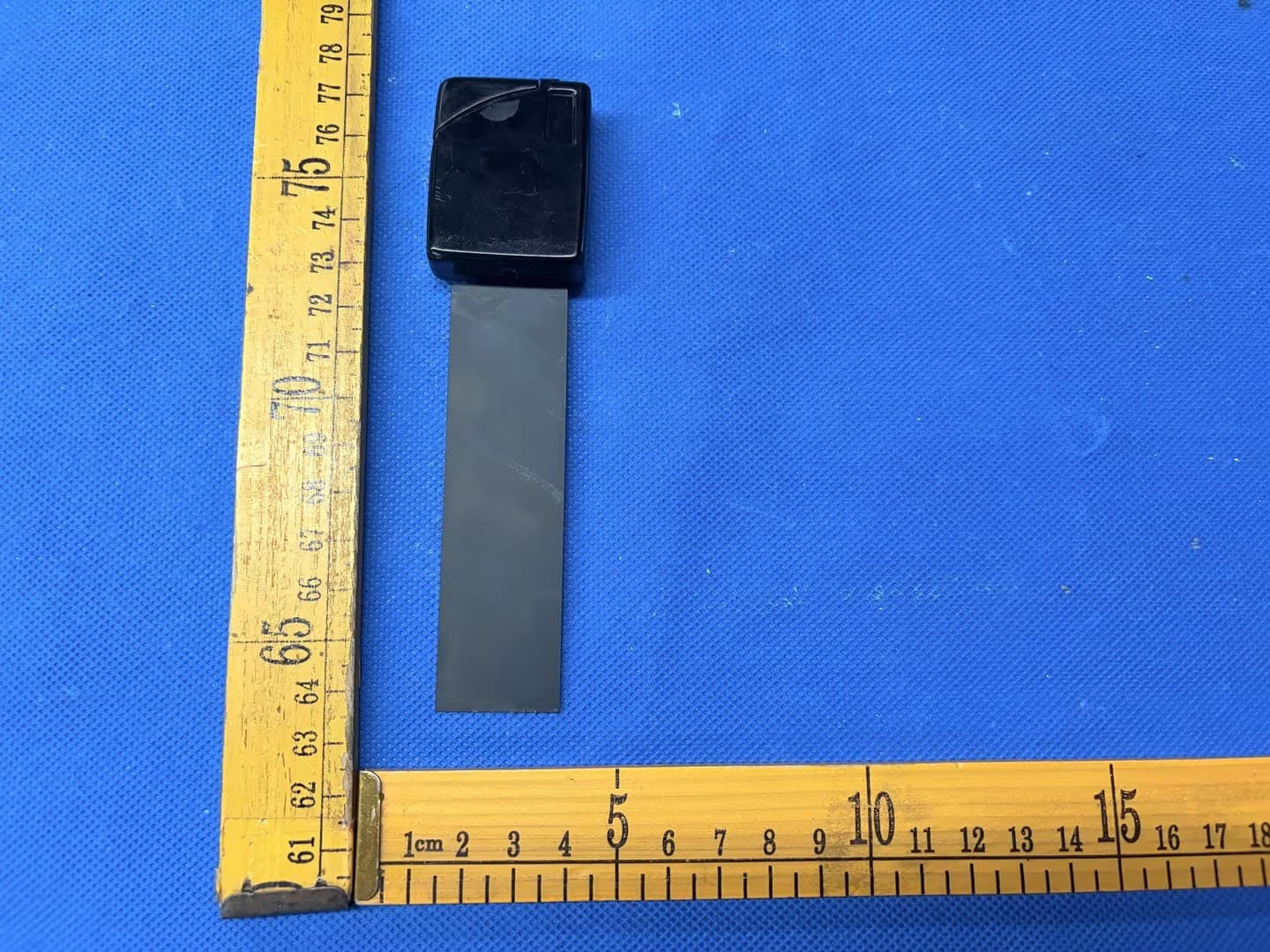
P6FM190
Jun 02, 2026M190 IR Enabled IT Asset Tag
Equipment Class
DSC - Part 15 Security/Remote Control Transmitter
P6F-MAT433
Jan 16, 2020Mobile Asset Tag
Equipment Class
DSC - Part 15 Security/Remote Control Transmitter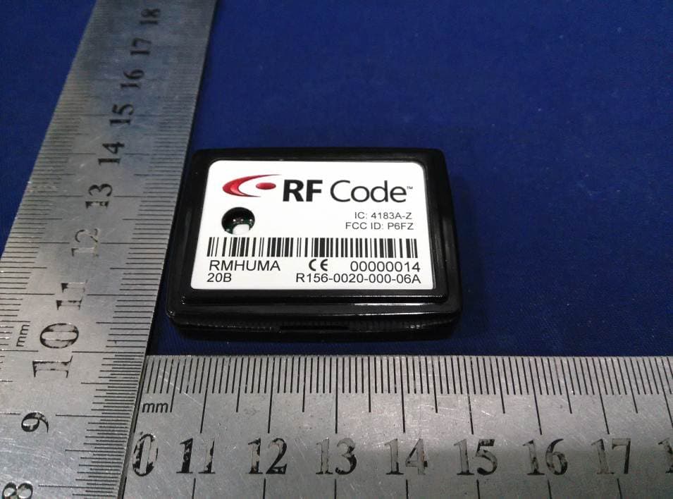
P6FZ
Apr 20, 2015Humidity-Temperature Tag
Equipment Class
DSC - Part 15 Security/Remote Control Transmitter
P6F4LTX
Jul 16, 2014Asset Tracking and Event Transmitter
Equipment Class
DTS - Digital Transmission SystemP6F4TFX
Nov 02, 2013Asset Tracking and Event TX
Equipment Class
DTS - Digital Transmission System