P6ZC100063UHF Base Station Transceiver
Westel Wireless Systems Pty Ltd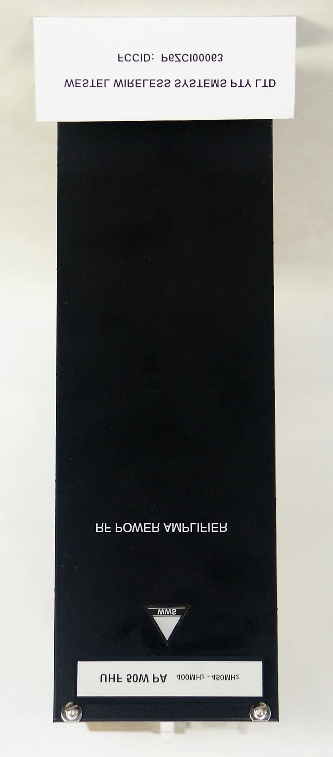
Click to zoom
Application Details
- Equipment Class
- TNB - Licensed Non-Broadcast Station Transmitter
- Date of Grant
- Jul 30, 2003
- Application Purpose
- Original Equipment
- Date of Application
- Jul 30, 2003
- Equipment Note
- UHF Base Station Transceiver
- Frequency Range
- 400.00000000 - 470.00000000
- Country
- Australia
Documents & Files
Document Text
Text extracted from the exhibit documents filed with the FCC. Open a document above to read the original.
Users Manual
Installation and Operator Handbook DRB-25 Diagnostics Monitor AMX-MA-00656 Issue 0.02 (USA) 1 TABLE OF CONTENTS Page 6 DRB-25 DIAGNOSTICS MONITOR 2 6.1 OVERVIEW 2 6.2 GETTING STARTED 2 6.2.1 System requirements 2 6.2.2 Making a Backup Copy of the DRB-25 Diagnostic Monitor Disk 2 6.2.3 Installing the DRB-25 Diagnostic Monitor Software 2 6.2.4 Starting DRB-25 Diagnostic Monitor for the First Time 3 6.2.5 Connecting the DRB-25 Diagnostic Monitor to the Controller Module 3 6.2.6 Getting Help 4 6.3 RUNNING THE DRB-25 DIAGNOSTIC MONITOR 4 6.3.1 Configuration 4 6.3.2 Configure Communications 4 6.3.3 Configure Polling Interval 6 6.3.4 Status/Test 6 6.3.5 Alarms 8 6.3.6 Test 9 6.3.7 Changing the Password 12 LIST OF FIGURES 6-1 DRB-25 Diagnostic Monitor Main Window..........................................................................................................................3 6-2 Configure Comms Dialog Box..................................................................................................................................................5 6-3 Polling Interval Dialog Box.......................................................................................................................................................6 6-4 Radio 1 and Radio 2 Status Dialog Box..................................................................................................................................8 6-5 Alarms Dialog Box.....................................................................................................................................................................9 6-6 Password Dialog Box..................................................................................................................................................................9 6-7 Test Radio Dialog Box.............................................................................................................................................................11 6-8 Change Password Dialog Box.................................................................................................................................................12 LIST OF TABLES 6-1 System Requirements.................................................................................................................................................................2 6-2 Communications Parameters.....................................................................................................................................................5 Installation and Operator Handbook DRB-25 Diagnostics Monitor AMX-MA-00656 Issue 0.02 (USA) 2 6 DRB-25 DIAGNOSTICS MONITOR 6.1 OVERVIEW DRB-25 Diagnostics Monitor is a Windows based software application running on an IBM compatible PC connected to the front panel RS-232 port (RJ-11) on the Controller Module of the DRB-25. ZDM allows an operator to monitor the activity and status of both transceiver modules together with the alarm status of all DRB-25 modules. 6.2 GETTING STARTED 6.2.1 System requirements The minimum system requirements for operation of the DRB-25 Diagnostics Monitor software application are given in Table 6-1. Table 6-1 System Requirements Component Minimum Recommended Computer 80386 Intel Pentium at 100 MHz Operating system Windows 3.1 Windows 95 or Windows NT RAM 4 Mb 16 Mb Hard disc free space 1.5 Mb 10 Mb Display type Super VGA Super VGA Display resolution 640 x 480 pixels 1024 x 768 pixels 6.2.2 Making a Backup Copy of the DRB-25 Diagnostic Monitor Disk To prevent accidental erasing or overwriting of files, it is recommended that a write-protected backup copy of the DRB-25 Diagnostics Monitor program disk be made prior to installation. 6.2.3 Installing the DRB-25 Diagnostic Monitor Software The following steps assume that the DRB-25 Diagnostic Monitor software is being installed from diskette drive A:\ or CD ROM on to hard drive D:\. If other drives are being used, make the appropriate substitutions in the following procedure. To install the DRB-25 Diagnostic Monitor software application: 1. Start Windows 2. Place the DRB-25 Diagnostic Monitor distribution diskette in a floppy disk drive on the PC or if the software was distributed on CDROM, place the CD in the CDROM drive. 3. Run File Manager (Windows 3.1) or Explorer (Windows98 and NT), and display the files on the distribution medium. Installation and Operator Handbook DRB-25 Diagnostics Monitor AMX-MA-00656 Issue 0.02 (USA) 3 4. Double-click on the file “setup.exe”. For floppy disk distributions this will be a top-level file, for CDROMS it may be located in a subdirectory named “disk1”. 5. Follow the instructions given by the Setup dialog boxes. If installation problems occur then contact the supplier. 6.2.4 Starting DRB-25 Diagnostic Monitor for the First Time To start the DRB-25 Diagnostic Monitor, select the ZDM icon from the Start | Programs menu. The DRB-25 Diagnostic Monitor main window will appear as shown in Figure 6.1. Figure 6-1 DRB-25 Diagnostic Monitor Main Window 6.2.5 Connecting the DRB-25 Diagnostic Monitor to the Controller Module To connect to a Controller Module: 1. A DRB-25 Programming Cable (ADI Part number AMX-CB-02272) is required. Connect the PC communications port to be used to the DRB-25 Controller Module RJ-11 serial port connector using the cable. 2. The DRB-25 Diagnostic Monitor will attempt to automatically establish communications with the Controller Module. If this is successful the status dialog boxes will open automatically. If not the Configure Comms dialog box will be opened. 3. Using the procedure given in Section “Configuring Communications”, set the PC communications port used to connect to the DRB-25, and the PC communication parameters required for the Controller Module. Installation and Operator Handbook DRB-25 Diagnostics Monitor AMX-MA-00656 Issue 0.02 (USA) 4 The Controller Module default communications settings are 9600 baud, 8 data bits, 1 stop bit and no parity (8N1). 6.…
Text truncated - open the document above for the full version.
Users Manual
Installation and Operator Handbook Installation Instructions AMX–MA–00653 Issue 0.03 (USA) 1 TABLE OF CONTENTS Page 3 Installation Instructions................................................................................................................................2 3.1 General....................................................................................................................................................2 3.2 Safety Precautions...................................................................................................................................2 3.3 Site Requirements....................................................................................................................................3 3.3.1 Antenna Installation and Safe Operating Distances.................................................................3 3.3.2 Desk/Floor Space or Rack Mounting Considerations..............................................................3 3.3.3 Lightning Protection.................................................................................................................4 3.4 Delivery and Unpacking..........................................................................................................................4 3.5 Installation...............................................................................................................................................5 3.5.1 Tools Required.........................................................................................................................5 3.5.2 Installing the DRB-25 Cabinet.................................................................................................5 3.5.3 Configuring DRB-25 Identity (Box ID)...................................................................................6 3.5.4 Installing the Modules..............................................................................................................7 3.6 Connections...........................................................................................................................................11 3.6.1 Grounding Strap.....................................................................................................................11 3.6.2 AC Power...............................................................................................................................11 3.6.3 DC Power...............................................................................................................................11 3.6.4 Antenna Cabling.....................................................................................................................11 3.6.5 External Interfaces..................................................................................................................11 LIST OF FIGURES 3-1 DRB-25 RACK MOUNTING ARRANGEMENT........................................................................................6 3-2 DRB-25 FRONT MODULE POSITIONS.....................................................................................................7 3-3 DRB-25 WITH LOUDSPEAKER AND MICROPHONE FITTED.............................................................8 3-4 DRB-25 REAR MODULE POSITIONS.......................................................................................................9 Installation and Operator Handbook Installation Instructions AMX–MA–00653 Issue 0.03 (USA) 2 3 INSTALLATION INSTRUCTIONS 3.1 GENERAL This chapter provides a detailed description of the installation procedure for the DRB-25 Dual Channel Radio System and should be read before starting the installation. Use the Installation Instructions in conjunction with the configuration checklist for the specific system being installed. 3.2 SAFETY PRECAUTIONS Observe standard safety procedures for the handling of electronic equipment: WARNING FOLLOW CORRECT LIFTING PROCEDURES FOR HEAVY ELECTRONIC EQUIPMENT. ATTENTION OBSERVE PRECAUTIONS FOR HANDLING ELECTROSTATIC SENSITIVE DEVICES When removing or handling cards, use an anti-static wrist strap connected to ground and always place the card on an anti-static mat Handle modules by their edges and do not touch components or connectors. Avoid placing the DRB-25 near any source of excessive heat Avoid placing the DRB-25 near a naked flame Avoid placing the DRB-25 in a wet or damp location Do not subject the DRB-25 to severe mechanical shock Installation and Operator Handbook Installation Instructions AMX–MA–00653 Issue 0.03 (USA) 3 3.3 SITE REQUIREMENTS Before installing the DRB-25 at the operating site, the following details regarding antenna installation and safe operating distances, desk or floor space, rack clearance and lightning protection should be considered. 3.3.1 Antenna Installation and Safe Operating Distances Use only manufacturer or dealer supplied antenna. Antenna Minimum Safe Distance: 70 cm, 50% Duty Cycle. Antenna Gain: zero dBd referenced to a dipole. The Federal Communications Commission has adopted a safety standard for human exposure to RF (Radio Frequency) energy which is below the OSHA Occupational Safety and Health Act) limits. Antenna Mounting: The antenna supplied by the manufacturer or radio dealer must not be mounted at a location such that during radio transmission, any person or persons can come closer than the above indicated minimum safe distance to the antenna i.e. 70 cm. To comply with current FCC RF Exposure limits, the antenna must be installed at or exceeding the minimum safe distance shown above, and in accordance with the requirements of the antenna manufacturer or supplier. Base Station Installation: The antenna should be fixed-mounted on an outdoor permanent structure. RF Exposure compliance must be addressed at the time of installation. Antenna Substitution: Do not substitute any antenna for the one supplied or recommended by the manufacturer or radio dealer. You may be exposing person or persons to excess …
Text truncated - open the document above for the full version.
Users Manual
Installation and Operators Handbook Appendix A AMX-MA-00658 Issue 0.02 (USA) A-1 APPENDIX A BOX ID AND TRANSCEIVER DEFAULT CHANNEL SETTINGS Table A-1 Box ID and Transceiver Default Settings Box ID Transceiver Default Channel Switch 1 (LSB) Switch 2 Switch 3 Switch 4 Switch 5 Switch 6 Switch 7 Switch 8 (MSB) TxRx 1 TxRx 2 0 0 1 Off Off Off Off Off Off Off Off 1 2 3 On Off Off Off Off Off Off Off 2 4 5 Off On Off Off Off Off Off Off 3 6 7 On On Off Off Off Off Off Off 4 8 9 Off Off On Off Off Off Off Off 5 10 11 On Off On Off Off Off Off Off 6 12 13 Off On On Off Off Off Off Off 7 14 15 On On On Off Off Off Off Off 8 16 17 Off Off Off On Off Off Off Off 9 18 19 On Off Off On Off Off Off Off 10 20 21 Off On Off On Off Off Off Off 11 22 23 On On Off On Off Off Off Off 12 24 25 Off Off On On Off Off Off Off 13 26 27 On Off On On Off Off Off Off 14 28 29 Off On On On Off Off Off Off 15 30 31 On On On On Off Off Off Off 16 32 33 Off Off Off Off On Off Off Off 17 34 35 On Off Off Off On Off Off Off 18 36 37 Off On Off Off On On Off Off 19 38 39 On On Off Off On On Off Off 20 40 41 Off Off On Off On On Off Off 21 42 43 On Off On Off On On Off Off 22 44 45 Off On On Off On On Off Off 23 46 47 On On On Off On On Off Off 24 48 49 Off Off Off On On On Off Off 25 50 51 On Off Off On On On Off Off 26 52 53 Off On Off On On On Off Off 27 54 55 On On Off On On On Off Off 28 56 57 Off Off On On On On Off Off 29 58 59 On Off On On On On Off Off 30 60 61 off On On On On On Off Off 31 62 63 On On On On On On Off Off 32 64 65 Off Off Off Off Off On Off Off 33 66 67 On Off Off Off Off On Off Off 34 68 69 Off On Off Off Off On Off Off 35 70 71 On On Off Off Off On Off Off 36 72 73 Off Off On Off Off On Off Off 37 74 75 On Off On Off Off On Off Off 38 76 77 Off On On Off Off On Off Off 39 78 79 On On On Off Off On Off Off 40 80 81 Off Off Off On Off On Off Off 41 82 83 On Off Off On Off On Off Off 42 84 85 Off On Off On Off On Off Off 43 86 87 On On Off On Off On Off Off 44 88 89 Off Off On On Off On Off Off 45 90 91 On Off On On Off On Off Off Installation and Operators Handbook Appendix A AMX-MA-00658 Issue 0.02 (USA) A-2 Box ID Transceiver Default Channel Switch 1 (LSB) Switch 2 Switch 3 Switch 4 Switch 5 Switch 6 Switch 7 Switch 8 (MSB) TxRx 1 TxRx 2 46 92 93 Off On On On Off On Off Off 47 94 95 On On On On Off On Off Off 48 96 97 Off Off Off Off On On Off Off 49 98 99 On Off Off Off On On Off Off 50 100 101 Off On Off Off On On Off Off 51 102 103 On On Off Off On On Off Off 52 104 105 Off Off On Off On On Off Off 53 106 107 On Off On Off On On Off Off 54 108 109 Off On On Off On On Off Off 55 110 111 On On On Off On On Off Off 56 112 113 Off Off Off On On On Off Off 57 114 115 On Off Off On On On Off Off 58 116 117 Off On Off On On On Off Off 59 118 119 On On Off On On On Off Off 60 120 121 Off Off On On On On Off Off 61 122 123 On Off On On On On Off Off 62 124 125 Off On On On On On Off Off 63 126 127 On On On On On On Off Off 64 128 129 Off Off Off Off Off Off On Off 65 130 131 On Off Off Off Off Off On Off 66 132 133 Off On Off Off Off Off On Off 67 134 135 On On Off Off Off Off On Off 68 136 137 Off Off On Off Off Off On Off 69 138 139 On Off On Off Off Off On Off 70 140 141 Off On On Off Off Off On Off 71 142 143 On On On Off Off Off On Off 72 144 145 Off Off Off On Off Off On Off 73 146 147 On Off Off On Off Off On Off 74 148 149 Off On Off On Off Off On Off 75 150 151 On On Off On Off Off On Off 76 152 153 Off Off On On Off Off On Off 77 154 155 On Off On On Off Off On Off 78 156 157 Off On On On Off Off On Off 79 158 159 On On On On Off Off On Off 80 160 161 Off Off Off Off Off Off On Off 81 162 163 On Off Off Off On Off On Off 82 164 165 Off On Off Off On Off On Off 83 166 167 On On Off Off On Off On Off 84 168 169 Off Off On Off On Off On Off 85 170 171 On Off On Off On Off On Off 86 172 173 Off On On Off On Off On Off 87 174 175 On On On Off On On On Off 88 176 177 Off Off Off On On On On Off 89 178 179 On Off Off On On On On Off 90 180 181 Off On Off On On On On Off 91 182 183 On On Off On On On On Off 92 184 185 Off Off On On On On On Off 93 186 187 On Off On On On On On Off 94 188 189 off On On On On On On Off 95 190 191 On On On On On On On Off 96 192 193 Off Off Off Off Off On On Off 97 194 195 On Off Off Off Off On On Off 98 196 197 Off On Off Off Off On On Off 99 198 199 On On Off Off Off On On Off Installation and Operators Handbook Appendix A AMX-MA-00658 Issue 0.02 (USA) A-3 Box ID Transceiver Default Channel Switch 1 (LSB) Switch 2 Switch 3 Switch 4 Switch 5 Switch 6 Switch 7 Switch 8 (MSB) TxRx 1 TxRx 2 100 200 201 Off Off On Off Off On On Off 101 202 203 On Off On Off Off On On Off 102 204 205 Off On On Off Off On On Off 103 206 207 On On On Off Off On On Off 104 208 209 Off Off Off On Off On On Off 105 210 211 On Off Off On Off On On Off 106 212 213 Off On Off On Off On On Off 107 214 215 On On Off On Off On On Off 108 216 217 Off Off On On Off On On Off 109 218 219 On Off On On Off On On Off 110 220 221 Off On On On Off On On Off 111 222 223 On On On On Off On On Off 112 224 225 Off Off Off Off On On On Off 113 226 227 On Off Off Off On On On Off 114 228 229 Off On Off Off On On On On 115 230 231 On On Off Off On On On On 116 232 233 Off Off On Off On On On On 117 234 235 On Off On Off On On On On 118 236 237 Off On On Off On On On On 119 238 239 On On On Off On On On On 120 240 241 Off Off Off On On On On On 121 242 243 On Off Off On On On On On 122 244 245 Off On Off On On On On On 123 246 247 On On Off On On On On On 124 248 249 Off Off On On On On On On 125 250 251 On Off On On On On On On 126 252 253 Off On On On On On On On 127 254 255 On On On On On On On On 128 256 257 Off Off Off Off Off Off Off On 129 258 259 On Off Off Off Off Off Off On 130 260 261 Off On Off Off Off Off Off On 131 262 263 On On Off Off Off Off Off On 132 264 265 Off Off On Off Off Off Off On 133 266 267 On Off On Off Off Off Off On 134 268 269 Off On On Off Off Off Off On 135 270 271 On On On Off Off …
Text truncated - open the document above for the full version.
Users Manual
Installation and Operators Handbook Appendix B AMX–MA–00659 Issue 0.02 (USA) B- 1 APPENDIX B MODULE ERROR CODES AND RECOMMENDED ACTIONS Table B-1: Error Codes E00 – E99 : User Serviceable Failures/Advisories Transceiver Module Controller Module Recommended Action E00 Reserved Reserved E01 - Internal 10MHz failure Either replace Controller Module or use external 10 MHz oscillator E02 – E03 Reserved Reserved E04 - DC Revert Active Check AC Power Supply E05 Channel Programming Error or Empty Channel Table - Check channel programming using Transceiver Module Programmer E06 PA Comms Failure - Check PA inserted correctly and power applied from PSU. If PSU fault light is on, or PSU power light is off, then replace PSU module. Otherwise replace PA module. E07 PA Over Temperature Alarm - Check fans operating correctly. E08 PA High VSWR Alarm - Check antenna connections. E09 Remote Diagnostics Active in Test Mode - An advisory, not an error condition E10 – E22 Reserved Reserved E23 - GPIO Xilinx boot failure Replace Controller Module E24 DSP boot failure DSP boot failure Replace Module E25 Reserved Reserved E26–E99 Not Used
Users Manual
Installation and Operator Handbook Introduction AMX–MA–00651 Issue 0.02 (USA) 1 CONTENTS Page 1 INTRODUCTION 1.1 OVERVIEW ............................................................................................................................................................2 1.2 P HYSICAL A RRANGEMENT ...................................................................................................................................4 1.2.1 General ........................................................................................................................................................4 1.2.2 Configuration Options .................................................................................................................................6 1.3 S PECIFICATIONS ...................................................................................................................................................8 1.3.1 General Specifications.................................................................................................................................8 1.3.2 Power Consumption ....................................................................................................................................8 1.3.3 Environmental Specifications......................................................................................................................8 1.3.4 Applicable Standards...................................................................................................................................9 LIST OF FIGURES F IGURE 1-1 F RONT V IEW - DRB-25..................................................................................................................................2 F IGURE 1-2 R EAR V IEW - DRB-25 ...................................................................................................................................3 F IGURE 1-3 B LOCK D IAGRAM - DRB-25 ..........................................................................................................................5 LIST OF TABLES T ABLE 1-1 DRB-25 O PERATIONAL C ONFIGURATIONS .....................................................................................................6 T ABLE 1-2 DRB-25 V OICE I NTERCONNECT C ONFIGURATION O PTIONS ...........................................................................7 T ABLE 1-3 DRB-25 P ROGRAMMING AND D IAGNOSTIC C ONFIGURATION O PTIONS ...........................................................7 T ABLE 1-4 G ENERAL S PECIFICATIONS ..............................................................................................................................8 T ABLE 1-5 P OWER C ONSUMPTION ....................................................................................................................................8 T ABLE 1-6 E NVIRONMENTAL S PECIFICATIONS .................................................................................................................8 T ABLE 1-7 A PPLICABLE S TANDARDS ................................................................................................................................9 Installation and Operator Handbook Introduction AMX–MA–00651 Issue 0.02 (USA) 2 1 INTRODUCTION 1.1 OVERVIEW This document describes the DRB-25 Dual Radio Base Station system installation procedures, configuration and operational details. The DRB-25, shown in Figure 1-1 and Figure 1-2, is a compact, multi-mode transceiver package which provides users with one or two analog or APCO Project 25 digital radio channels. The small size and high level of flexibility of the DRB-25 make it an ideal solution for any organization starting out on the digital migration path. Figure 1-1 Front View - DRB-25 Installation and Operator Handbook Introduction AMX–MA–00651 Issue 0.02 (USA) 3 Figure 1-2 Rear View - DRB-25 The DRB-25 provides one or two independent radios in a single package. Each radio can be used as a base station or a repeater, and may be configured to support both APCO Project 25 compliant digital subscribers as well as providing backwards compatibility to analog users. This means that existing mobile radio equipment need not be immediately retired. Each radio may be configured to provide an analog interface (2 wire with loop or ground start or 4 wire with E & M signaling) to the public switched telephone network (PSTN), to a private branch exchange (PBX), or to existing tone based remote control units. The DRB-25 provides the key elements of an APCO Project 25 RF Sub-system including the air interface (Um), interfaces for telephone and PBX interconnect (Et) and host data systems (Ed). Support for Ethernet based network management, digital consoles and the APCO Project 25 fixed station interface (Ef) will be available as software upgrades. Installation and Operator Handbook Introduction AMX–MA–00651 Issue 0.02 (USA) 4 The DRB-25 provides the following features: • Automatically and concurrently supports the digital mobile and FM analog radios (TIA/EIA 603 including CTCSS selective calling). • VHF (136-174 MHz) or UHF (400-470 MHz) frequency bands. • 60 W or 125 W RF output. • Configurable as single or dual channel with any mix of frequency bands and output power levels. • 512 programmable channels per radio, with each channel programmable as APCO Project 25 digital or TIA/EIA 603 analog. • Programmable channel scan of up to eight channels. • Optional RS232, RS485, Ethernet and general purpose I/O interfaces. • Optional 2 wire or 4 wire + E&M wire line interfaces for remote control or telephone interconnect. • Compatible with industry standard tone remote control consoles. • Compatible with Microwave Links using 4 Wire and E & M signaling. • User friendly Windows configuration and diagnostic software for local or remote configuration. • Self test diagnostic routines. • 240/110 VAC or 12, 24 or 48 VDC versions. • Available as a standard 19” rack mount sub-rack, as a desktop unit or housed in a …
Text truncated - open the document above for the full version.
Users Manual
Installation and Operator Handbook Operating Instructions AMX-MA-00654 Issue 0.02 (USA) 1 TABLE OF CONTENTS Page 4 OPERATING INSTRUCTIONS 4.1 INTRODUCTION....................................................................................................................................2 4.2 SWITCHES..............................................................................................................................................2 4.3 APPLYING POWER ...............................................................................................................................2 4.3.1 Initial Power-On Checklist ........................................................................................................3 4.3.2 Power-On Faultfinding..............................................................................................................3 4.3.3 Fuse Replacement .....................................................................................................................4 4.3.4 Checking System Power Supply Outputs..................................................................................4 4.3.5 Replacing System Power Supply ..............................................................................................4 4.4 OPERATIONAL FAULTFINDING........................................................................................................5 4.5 CONFIGURATION .................................................................................................................................7 4.5.1 Fixed Channel Operation ..........................................................................................................7 4.5.2 Scan Channel Operation............................................................................................................7 4.6 LOCAL OPERATION .............................................................................................................................7 4.6.1 Monitoring Audio......................................................................................................................7 4.6.2 Making Calls .............................................................................................................................8 4.6.3 Changing Audio Volume ..........................................................................................................8 4.6.4 Changing Selected Channel: .....................................................................................................8 4.6.5 Squelch Adjustment ..................................................................................................................8 4.7 REMOTE OPERATION ..........................................................................................................................8 LIST OF TABLES 4-1 RESET SWITCHES.......................................................................................................................................2 4-2 POWER-ON INDICATORS ..........................................................................................................................3 4-3 FAULTFINDING CHART FOR POWER ON PROBLEMS ........................................................................3 4-4 FAULTFINDING CHART FOR OPERATIONAL PROBLEMS .................................................................5 Installation and Operator Handbook Operating Instructions AMX-MA-00654 Issue 0.02 (USA) 2 4 OPERATING INSTRUCTIONS 4.1 INTRODUCTION After installation (as described in Chapter 3), normal operation of the DRB-25 is achieved by applying power to the DRB-25 and switching on the rear panel power switch and the Power Supply Modules. The DRB-25 Modules will perform self-test diagnostics after power is applied. Visual indicators on the module front panels will convey the status of the DRB-25 to the Operator. If any of these visual indicators show an error or fault code, simple faultfinding procedures may identify the problem and suggest an immediate solution. If operational checks reveal a fault in DRB-25 equipment, it may be necessary to replace it. Removal of equipment is the reverse of the installation procedure described in Chapter 3. Any faulty items should be carefully packaged and sent to an authorized repair center. If faults are not corrected by substituting equipment at an operational level, contact the supplier or its representative. Additional connectors on the front and back panels of selected equipment allow maintenance personnel to access functions for system configuration, operational statistics and faultfinding. 4.2 SWITCHES There are two types of switches on the front panels of the DRB-25: power and reset switches. If an AC supply is used with the DRB-25, there is a master power supply switch on the rear of the unit which should be turned on first. The power s…
Text truncated - open the document above for the full version.
Contact Information
Applicant
Steve Tucker(Chief Technical Officer)
Test Firm
M. Flom Associates, Inc.Morton Flom
Technical Specifications
| # | Rule Parts | Frequency Range | Power Output | Emission | Tolerance |
|---|---|---|---|---|---|
| 4 | 90.21 | 400 MHz - 470 MHz | 60 W | 11K0F3E | 1.5 ppm |
Other Applications from Westel Wireless Systems Pty Ltd

P6ZCI00066
Dec 14, 2004Base Station 100W VHF
Equipment Class
TNB - Licensed Non-Broadcast Station Transmitter
P6ZCI00063
Aug 21, 2003UHF BASE STATION TRANSCEIVER
Equipment Class
TNB - Licensed Non-Broadcast Station Transmitter