P7L-30101Tracking System
Digital Innovations L.L.C.
Click to zoom
Application Details
- Equipment Class
- DSC - Part 15 Security/Remote Control Transmitter
- Date of Grant
- Feb 03, 2003
- Application Purpose
- Original Equipment
- Date of Application
- Feb 03, 2003
- Equipment Note
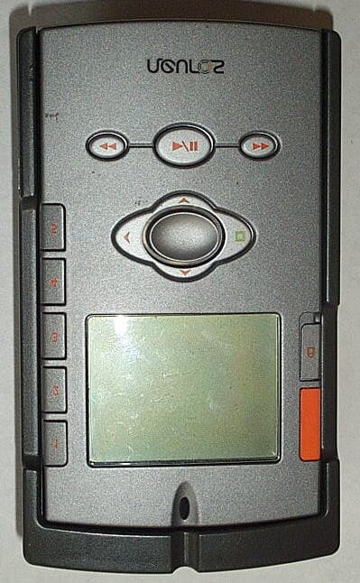
- Tracking System
- Frequency Range
- 303.82500000 - 303.82500000
- Company
- Digital Innovations L.L.C.
- Country
- United States
Documents & Files
Document Text
Text extracted from the exhibit documents filed with the FCC. Open a document above to read the original.
Users Manual
OPERATING GUIDE - 2 - FCC Information Compliance Statement The Transmitter and each Receiver comply with Part 15 of the FCC Rules and with RSS-210 of Industry Canada. Operation is subject to the following two conditions: 1. This device may not cause harmful interference, and 2. This device must accept any interference received, including interference that may cause undesired operation. Tested to Comply With FCC Standards FOR HOME OR OFFICE USE IC: 4252A-30101 Warning Changes or modifications not expressly approved by the party responsible could void the user’s authority to operate the equipment. - 3 - Read Me First! Your i-SPOT receivers must be programmed by the transmitter before use in order for the receivers to operate. To ensure your set-up is hassle-free, please read the instructions carefully before removing the protective battery liner from the receivers. Introduction Congratulations on being a proud owner of the i-SPOT Expandable Object Tracking System! Never again will you have to spend hours searching your home for misplaced car keys, remote controls, or other personal belongings as long as an i-SPOT receiver is attached. If you have any questions not answered within this Operating Guide, go to www.digitalinnovations.com/support, e-mail us at [email protected], or call us toll- free at 1-888-SMART-58, Monday through Friday from 9:00 a.m. to 5:00 p.m. central standard time. For information about i-SPOT accessories and replacement parts or other Digital Innovations products visit our website at www.digitalinnovations.com or call us at 1-888-SMART-58. - 4 - Table of Contents Setting up Identifying the Parts 5 Transmitter Installing Batteries (not supplied) 6 Lens Removal/Quick Reference Card 6 Receiver Programming Receivers 7 Attaching Receivers Tape Method 7 Key Fob Method 8 Docking Station Configuring for Desktop Use 9 Attaching to a Wall 9 General use Finding an Object 11 Storing the Transmitter 11 Transmitter Locator Tone 11 Enabling / Disabling Transmitter Locator Tone 12 Avoiding Interference 12 Batteries Receiver Low Battery Alarms 13 Replacing Receiver Battery 13 Transmitter Low Battery Indicator 13 Troubleshooting 14 Warranty Back Cover - 5 - Setting Up - Identifying the Parts Did You Know? Each receiver and transmitter is digitally encoded to eliminate any false alarms or interference. Transmitter Key Ring (x3) Wall Anchor (x2) Docking Station Receiver (x3) Key Fob (x3) - 6 - Setting Up - Transmitter Installing Batteries Your i-SPOT transmitter requires 2-AAA batteries (not supplied). To remove the battery door, pull the tab on the back and rotate the door out of the transmitter. Install batteries by inserting the negative end (flat end) of the battery in first against the spring coil and then push the positive end of the battery into place. Replace the battery door by inserting the two tabs on the door into the transmitter and then rotating until it snaps back into place. Lens Removal / Quick Reference Card To remove the lens, rotate the lens out of the housing by using the fingernail groove located at the bottom of the lens. Remove the reference card, label as required and reposition on the transmitter, lining up the card with the holes for the lens tabs and hook. Reassemble the lens by inserting the two tabs into the top of the transmitter housing and then rotating the lens back until it snaps into place. Lift and rotate lens Fingernail groove Lens Removal Lens Assembly - 7 - Setting Up - Receivers Programming Receivers Please read completely before removing battery liner. If this is the first time the receiver is used, you will need to remove the battery liner by pulling the hang tab. Once the liner is removed, the receiver will start to beep and you have 30 seconds to program it. Next, select the button on the transmitter you wish to correspond to this receiver. After you push a transmitter button, the receiver will give off 3 quick beeps to indicate it has been successfully programmed. To confirm the receiver has been programmed correctly, push the corresponding button on the transmitter. The receiver should now give off the standard locating beeps for approximately 7 seconds. Note: If you did not push a transmitter button within the 30 seconds or the battery becomes dislodged you will need to re- install the receiver battery and repeat the steps above for programming. Attaching Receiver – Tape Method Simply remove the liner from the double-sided tape found on the back of the receiver and firmly press the receiver against the object. For best performance, avoid attaching the receiver over locations with batteries or battery doors. Note: For the receiver to adhere properly, the object’s surface should be flat and clean from dirt and fingerprints. - 8 - Setting Up - Receivers Attaching Receiver – Key Fob Method Orient the receiver so the i-SPOT logo is opposite the three key ring holes on the key fob housing. Press the key fob housing against the receiver until it snaps into place. Now attach the supplied key ring to any of the three holes and attach the ring to your existing key ring or other object. Note: Do not remove the tape liner when using the receiver with the key fob. Assemble the key fob so the key ring holes are opposite the “I-Spot” logo. - 9 - Setting Up - Docking Station The i-SPOT docking station helps ensure your i-SPOT transmitter is never lost. When the transmitter is out of the docking station and a button has not been pressed for over 10 minutes the transmitter will begin to beep to remind you to place the transmitter back into the docking station. For more information on the Transmitter Locator function see page 11. Configuring for Desktop Use The i-SPOT docking station can swivel from wall-mount to desktop use by rotating the base either clockwise or counter- clockwise 180 degrees until it snaps into place. Attaching to a Wall (using the wall anchors) In order to mount the i-SPOT docking station to a wall using the wall an…
Text truncated - open the document above for the full version.
Cover Letter(s)
F C C CONFIDENTIALITY Date: 6/4/02 To: FEDERAL COMMUNICATIONS COMMISSION 7435 Oakland Mills Road Columbia, MD 21046 Subject: Request for Non disclosure for FCC ID: P7L - 30101. To Whom It May Concern: Pursuant to 47 CFR Section 0.459, Digital Innovations L.L.C. hereby requests non disclosure and confidential treatment of the following materials submitted in support of FCC certification application for FCC ID #P7L - 30101. a. Schematic Diagrams b. Operational Description c. Block Diagram Above materials contain trade secrets, proprietary and technical information which would customarily be guarded from competitors under 47 CFR section 0.457(d)(2). Disclosure or publication of any portion of this company confidential material to other parties could cause substantial competitive harm and provide unjustified benefits for competitors. Digital Innovations L.L.C. understands that pursuant to 47 CFR section 0.457(d)(1)(ii) disclosure of the applicant and all accompanying documentation will not be made before the date of the grant. Sincerely yours, Paul Holbrook Vice President – New Product Development Digital Innovations L.L.C. 7250 N. Cicero Ave. Lincolnwood, IL 60712 Phone: 847 676 4200, x16 Fax: 847 676 4220
External Photos
Digital Innovations L.L.C. iSpot expandable tracking system FCC ID#: P7L-30101 Canada ID Number: 4252A-30101 Photo One iSpot Membrane Control Pad Digital Innovations L.L.C. iSpot expandable tracking system FCC ID#: P7L-30101 Canada ID Number: 4252A-30101 Photo Two iSpot Battery Compartment with FCC ID Label
ID Label/Location Info
Digital Innovations L.L.C. iSpot expandable tracking system FCC ID#: P7L-30101 Canada ID Number: 4252A-30101 Photo Nine In addition to the Product Label on the Battery Cover, the FCC ID and Canada ID Numbers will be “Molded” into the top cover Plastic Housing of the i-Spot
ID Label/Location Info
TX BATTERY DOOR LABEL SCALE 1:1
Internal Photos
Digital Innovations L.L.C. iSpot expandable tracking system FCC ID#: P7L-30101 Canada ID Number: 4252A-30101 Photo Five Open for Inspection Digital Innovations L.L.C. iSpot expandable tracking system FCC ID#: P7L-30101 Canada ID Number: 4252A-30101 Photo Six PCB Component Side Digital Innovations L.L.C. iSpot expandable tracking system FCC ID#: P7L-30101 Canada ID Number: 4252A-30101 Photo Seven PCB Flip Side with Battery Connections Digital Innovations L.L.C. iSpot expandable tracking system FCC ID#: P7L-30101 Canada ID Number: 4252A-30101 Photo Eight PCB Antenna
Test Report
L.S. Compliance, Inc. W66 N220 Commerce Court Cedarburg, WI 53012 262-375-4400 Fax: 262-375-4248 Compliance Testing of the Digital Innovation’s i-Spot Transmitter Prepared For: Paul Holbrook Vice President- New Product Development Digital Innovations, LLC 7250 North Cicero Ave. Lincolnwood, IL 60712 Test Report Number: 302125 TX Test Dates: December 30 th and 31 st , 2002 All results of this report relate only to the items that were tested. This report may not be reproduced, except in full, without written approval of L.S. Compliance, Inc. ________________________________________________________________________ Page 2 of 21 L.S. Compliance, Inc. Prepared For: Paul Holbrook, Digital Innovations, LLC Test Report Number: 302125 TX Table of Contents Section Description Type of Test Page # Index 2 1 L. S. Compliance in Review 3 2 A2LA Certificate of Accreditation 4 3 A2LA Scope of Accreditation 5 4 Validation Letter- U.S. Competent Body for EMC Directive 89/336/EEC 6 5 Signature Page 7 6 Product General Information 8 7 Introduction 8 8 Purpose 8 9 Product Description 9 10 Test Requirements 9 11 Summary of Test Report 9 12 Radiated Emission Test 10-18 Appendices A Calculations 19-20 B Test Equipment List 21 ________________________________________________________________________ Page 3 of 21 L.S. Compliance, Inc. Prepared For: Paul Holbrook, Digital Innovations, LLC Test Report Number: 302125 TX 1. L.S. Compliance in Review L. S. Compliance, Inc. is located in Cedarburg, Wisconsin – United States. We may be contacted by: Mail: L. S. Compliance, Inc. W66 N220 Commerce Court Cedarburg, Wisconsin 53102 Phone: 262-375-4400 Fax: 262-375-4248 E-Mail: [email protected] As an EMC testing laboratory, our accreditation and assessments are recognized through the following: A2LA – American Association for Laboratory Accreditation Accreditation based on ISO/IEC 17025: 2001 With electrical (EMC) Scope of Accreditation A2LA Certificate Number: 1255.01 U.S. Conformity Assessment Body (CAB) Validation Validated by the European Commission as a U.S. conformity assessment Body operating under the U.S./EU, Mutual Recognition Agreement (MRA) operating under the European Union EMC Directive 89/336/EEC, Article 10.2 Date of Validation: January 16, 2001 Federal Communications Commission (FCC) – USA Listing of 3 Meter Semi-Anechoic Chamber based on 47CFR 2.948 FCC Registration Number: 90756 Listing of 3 and 10 Meter OATS based on 47CFR 2.948 FCC Registration Number: 90757 Industry Canada On-file, 3 Meter Semi-Anechoic Chamber based on 47CFR 2.948 File Number: IC 3088 On-file 3 and 10 meter OATS based on RSS-210 File Number: IC 3088-A ________________________________________________________________________ Page 4 of 21 L.S. Compliance, Inc. Prepared For: Paul Holbrook, Digital Innovations, LLC Test Report Number: 302125 TX 2. A2LA Certificate of Accreditation ________________________________________________________________________ Page 5 of 21 L.S. Compliance, Inc. Prepared For: Paul Holbrook, Digital Innovations, LLC Test Report Number: 302125 TX 3. A2LA Scope of Accreditation ________________________________________________________________________ Page 6 of 21 L.S. Compliance, Inc. Prepared For: Paul Holbrook, Digital Innovations, LLC Test Report Number: 302125 TX 4. Validation Letter – U.S. Competent Body for EMC Directive 89/336/EEC ________________________________________________________________________ Page 7 of 21 L.S. Compliance, Inc. Prepared For: Paul Holbrook, Digital Innovations, LLC Test Report Number: 302125 TX 5. Signature Page January 28, 2003 Prepared By: ________________________________________________________ Teresa A. White, Document Coordinator Date January 28, 2003 Tested By: ________________________________________________________ Abtin Spantman, EMC Engineer Date January 28, 2003 Approved By: ________________________________________________________ Kenneth L. Boston, EMC Lab Manager Date PE #31926 Licensed Professional Engineer Registered in the State of Wisconsin, United States ________________________________________________________________________ Page 8 of 21 L.S. Compliance, Inc. Prepared For: Paul Holbrook, Digital Innovations, LLC Test Report Number: 302125 TX 6. Product and General Information Digital Innovations, LLC i-Spot Transmitter Engineering Unit #3 319 MHz Manufacturer: Model Number: Serial Number: Frequency Range: Test Voltage: 3.0 VDC Environmental Conditions in the Test Lab: Temperature: 20-25? C Atmospheric Pressure: 86kPa-106kPa Humidity: 30-60% 7. Introduction On December 30 and 31 st , 2002, a series of Radiated Emissions tests were performed on one sample of the Digital Innovations’ transmitter, Serial Number 3, hereafter referred to as the equipment under test (EUT). This product operates by means of RF transmission of short burst of data containing a command code, in a simplex fashion. The transmitter is designed to operate with amplitude-shift-keying (ASK) modulation, at a carrier frequency of 319.5 MHz. These tests were performed using the test procedure outlined in ANSI C63.4, 2001 for intentional radiators, and in accordance with the limits set forth in FCC Part 15.231, for a periodic operation of a low power transmitter. 8. Purpose The above-mentioned tests were performed in order to determine the compliance of the equipment under test, as compared to the limits contained in various provisions of Title 47CFR, FCC Part 15, including: 15.205, 15.209, 15.231a, 15.231b, and 15.231c. Radiated emission tests were performed to measure the emissions in the frequency bands described in section 12i of this report, and to determine whether said emissions are below the limits established by the aforementioned standards. These tests were performed in accordance with the procedures described in the American National Standard for methods of measurements of Radio-Noise Emissions from Low-Voltage Electrical and Electronic Equipment in the Range of 9 kHz to 40 GHz (ANSI C63.4, 2001). Also …
Text truncated - open the document above for the full version.
Test Report
12i. Measurement of Electromagnetic Radiated Emission Measurement of Electromagnetic Radiated Emission Within the 3 Meter Semi-Anechoic FCC Listed Chamber Digital Innovations. December 30 th and 31 st , 2002 i-Spot transmitter 3 Manufacturer: Date of Test: Model: Serial: Test Specifications: Radiated Emissions 15.205, 15.209, 15.231a, 15.231b, and 15.231c. Distance: 3 Meters Frequency Range Inspected: 30 to 6000 MHz Configuration: Normal and CW modes Detector(s) Used: √ Peak Quasi-Peak Average Test Equipment Used: EMI Receiver: HP 8546A Log Periodic Antenna: EMCO 93146 Double-Ridged Horn Antenna: EMCO 3115 Biconical Antenna: EMCO 93110B The following tables depict the level of significant fundamental and harmonic emissions found during the tests on the EUT. All other emissions were better than 20 dB below the limit. Frequency (MHz) Antenna Polarity Height (Meters) Azimuth (0◦-360◦) EMI Meter Reading (Peak dBμV/m) Duty Cycle Relaxation Allowance (dB) Meter Reading After Relaxation (dBμV/m) 15.231b Limit with Allowed Relaxation (dBμV/m) Margin (dB) 319.5 H 1.00 315 76.8 4.9 71.9 75.9 4.0 639.0 H 1.25 215 58.4 4.9 53.5 55.9 2.4 958.5 V 1.15 95 53.5 4.9 48.6 55.9 7.3 1278.0 H 1.20 175 57.3 4.9 52.4 55.9 3.50 1597.5 V 1.00 240 42.7 4.9 37.8 54.0 16.2 1917.0 V 1.20 100 46.8 4.9 41.9 55.9 14.0 2236.5 V 1.20 245 49.0 4.9 44.1 54.0 9.9 2556.0 H 1.05 170 45.6 4.9 40.7 55.9 15.2 2875.5 H 1.15 100 41.4 4.9 36.5 54.0 17.5 3195.0 H 1.00 0 28.0 4.9 23.1 55.9 32.8
Test Setup Photos
________________________________________________________________________ Page 12 of 21 L.S. Compliance, Inc. Prepared For: Paul Holbrook, Digital Innovations, LLC Test Report Number: 302125 TX 12f. Photo of Setup for Radiated Emissions Test EUT placed in horizontal orientation inside the 3 Meter Semi-Anechoic Chamber
Contact Information
Applicant
Paul R Holbrook(Vice President - New Product Development)
Test Firm
L. S. Compliance, Inc.James Blaha
262-375-4400Fax: 262-375-4248
Technical Specifications
| # | Rule Parts | Frequency Range | Power Output |
|---|---|---|---|
| 1 | 15.231 | 303.825 MHz - 303.825 MHz | - |
Other Applications from Digital Innovations L.L.C.
P7L11774
Jan 08, 2003LOW-POWER TRANSMITTER
Equipment Class
DXX - Part 15 Low Power Communication Device Transmitter