P9J-BFD802.11 a/b/g Module
Hitachi Energy USA, Inc.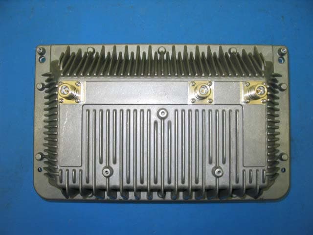
Click to zoom
Application Details
- Equipment Class
- DTS - Digital Transmission System
- Date of Grant
- Aug 02, 2006
- Application Purpose
- Original Equipment
- Date of Application
- Aug 02, 2006
- Equipment Note
- 802.11 a/b/g Module
- Frequency Range
- 5745.00000000 - 5825.00000000
- Company
- Hitachi Energy USA, Inc.
- Country
- United States
Documents & Files
Document Text
Text extracted from the exhibit documents filed with the FCC. Open a document above to read the original.
Users Manual
Part No. 200197-00 Rev A0 July 2006 Tropos Networks MetroMesh Router Installation Guide Model 5320 Tropos Networks, Inc. 555 Del Rey Ave. Sunnyvale, CA 94085 USA Tropos 5320 MetroMesh Router Installation Guideii Copyright Notice ©2006 Tropos Networks, Inc. All rights reserved. Tropos Networks is a registered trademark of Tropos Networks, Inc. in the United States and certain other jurisdictions. Specifications are subject to change without notice. Loctite is a registered trademark of Loctite Corporation, USA. This product includes technology protected by U.S. Patents 6,704,301; 6,965,575; 7,016,328, and 7,031,293. FCC Notice to Users and Operators This device complies with Part 15 of the FCC Rules. Operation is subject to the following two conditions: (1) this device may not cause harmful interference, and (2) this device must accept any interference received, including interference that may cause undesired operation. This equipment has been tested and found to comply with the limits for a Class B digital device, pursuant to Part 15 of the FCC Rules. These limits are designed to provide reasonable protection against harmful interference when the equipment is operated in a commercial environment. This equipment generates, uses, and can radiate radio frequency energy and, if not installed and used in accordance with the instruction manual, may cause harmful interference to radio communications. Operation of this equipment in a residential area is likely to cause harmful interference, in which case the user will be required to correct the interference at his own expense. If this equipment does cause interference to radio or television reception, which can be determined by turning the equipment off and on, the user is encouraged to correct the interference by using one of the following measures: Reorient or relocate the receiving antenna. Increase separation between the equipment and receiver. Connect the equipment to an outlet on a circuit different from that to which the receiver is connected. Consult the dealer or an experienced radio/TV technician. This Part 15 radio device operates on a non-interference basis with other devices operating at this frequency. Any changes or modification to said product not expressly approved by Tropos Networks could void the user's authority to operate this device. Industry Canada Notice to users and operators: This Class B digital apparatus meets all requirements of the Canadian Interference Causing Equipment Regulations. Operation is subject to the following two conditions: (1) this device may not cause harmful interference, and (2) this device must accept any interference received, including interference that may cause undesired operation. Tropos 5320 MetroMesh Router Installation Guideiii Cet appareillage numérique de la classe B répond à toutes les exigences de l’interférence canadienne causant des réglements d’équipement. L’opération est sujette aux deux conditions suivantes : (1) cet dispositif peut ne pas causer l'interférence nocive, et (2) ce dispositif doit accepter n’importe quelle interférence reçue, y compris l'interférence qui peut causer l’opération peu désirée. Warning It is illegal to modify the construction of this product. Modifying the operating frequency or enhancing the transmit output power through the use of external amplifiers or other equipment is specifically disallowed by the “Telecommunications Act.” Warning This device is for outdoor or indoor use with conditions that no harmful interference to authorized radio stations results from the operation of this device. This device shall not influence aircraft security and/or interfere with legal communications as defined in the “Telecommunications Act.” If this device is found to cause interference, the operator of this equipment shall cease operating this device immediately until no interference is achieved. European Union WEEE Notice It is important for users of this equipment to participate in reuse, recycling, and other forms of recovery. The potential effects on the environment and human health as a result of the presence of hazardous substances in electrical and electronic equipment are a waste of natural resources and cause pollution. For EU member countries, this symbol means: Do not dispose of this equipment as unsorted municipal waste. This equipment must be collected separately. The return and collection of this product has not been defined at this time, please contact Tropos Networks for return and/or collection. Tropos 5320 MetroMesh Router Installation Guideiv European Community Language Versions of Informal Statement for Inclusion in User Information The following statements are in accordance with Article 6.3 of Directive 1999/5/EC. Tropos 5320 MetroMesh Router Installation Guidev STOP!! STOP!! STOP!! STOP!! READ THIS FIRST! Important Safety Instructions The exclamation point within an equilateral triangle is intended to alert the user to the presence of important operating and maintenance (servicing) instructions in the literature accompanying the product. The lightning flash with an arrowhead symbol within an equilateral triangle is intended to alert the user to the presence of uninsulated “dangerous voltage” within the product’s enclosure that may be of sufficient magnitude to constitute a risk of electric shock to persons. Caution Read these instructions. Keep these instructions. Heed all warnings. Follow all instructions. Do not defeat the safety purpose of the grounding. Only use attachments/accessories specified by the manufacturer. Refer all servicing to qualified service personnel. Servicing is required when the apparatus has been damage in any way, such as power-supply cord or plug is damaged, liquid has been spilled on objects have fallen into the apparatus, the apparatus has been exposed to rain or moisture, does not operate normally, or has been dropped. Tropos 5320 MetroMesh Router Installation Guidevi Warning Risk of personal injury or death when in…
Text truncated - open the document above for the full version.
Cover Letter(s)
June 14, 2006 Compliance Certification Services Certification Division 561F Monterey Road Morgan Hill, CA 95037 To whom it may concern: We, the undersigned, hereby authorize the Testing Division of Compliance Engineering Services, Inc., d.b.a. Compliance Certification Services and hereafter referred to as CCS, to act on our behalf in all manners relating to application for equipment authorization, including signing of all documents relating to these matters. Any and all acts carried out by CCS on our behalf shall have the same effect as acts of our own. We, the undersigned, hereby certify that we are not subject to a denial of federal benefits, that includes FCC benefits, pursuant to Section 5301 of the Anti-Drug Abuse Act of 1988, 21 U.S.C. 853(a). In authorizing CCS Testing Division as our agent, we still recognize that we are responsible to: a) comply with the relevant provisions of the certification program; b) make all necessary arrangements for the conduct of the evaluation, including provision for examining documentation and access to all areas, records (including internal audit reports) and personnel for the purposes of evaluation (e.g. testing, inspection, assessment, surveillance, reassessment) and resolution of complaints; c) make claims regarding certification only in respect of the scope for which certification has been granted; d) do not use our product certification in such a manner as to bring the Certification Division into disrepute and not make any statement regarding our product certification which the Certification Division may consider misleading or unauthorized; e) upon suspension or cancellation of certification, discontinue use of all advertising matter that contains any reference thereto and return any certification documents as required by the Certification Division; f) use certification only to indicate the products are certified as being in conformity with specified standards; g) endeavor to ensure that no certificate or report nor any part thereof is used in a misleading manner; h) ensure that any reference to our product certification in communication media such as documents, brochures or advertising, complies with the requirements of the Certification Division; i) keep a record of all complaints made known to the us relating to the product’s compliance with requirements of the relevant standard and to make these records available to the Certification Division when requested; j) take appropriate action with respect to such complaints and any deficiencies found in products or services that affect compliance with the requirements for certification; k) document the actions taken. This authorization is valid until further written notice from the applicant. Sincerely Yours, Tom Blais Director of Hardware Engineering Tropos Networks
Cover Letter(s)
Federal Communications Commission 7435 Oakland Mills Road Columbia MD 21046 Subject: Request for Confidentiality FCC ID: P9J-BFD To Whom It May Concern: Pursuant to the provisions of Sections 0.457 and 0.459 of the Commission’s rules (47 CFR §§ 0.457, 0.459), we are requesting the Commission to withhold the following attachments as confidential document from public disclosure indefinitely. Schematic Diagram Block Diagram Theory of Operation Above mentioned document contains detailed system and equipment description are considered as proprietary information in operation of the equipment. The public disclosure of above documents might be harmful to our company and would give competitor an unfair advantage in the market. In additional to above mentioned documents, pursuant to Public Notice DA 04-1705 of the Commission’s policy, in order to comply with the marketing regulations in 47 CFR §2.803 and the importation rules in 47 CFR §2.1204, while ensuring that business sensitive information remains confidential until the actual marketing of newly authorized devices. We are requesting the commission to grant short-term confidentiality request on the following attachments: External Photos Internal Photos Test Setup Photos User Manual It is our understanding that all measurement test reports, FCC ID label format and correspondent during certification review process cannot be granted as confidential documents and those information will be available for public review once the grant of equipment authorization is issued. Best Regards Jay Kruse Principal RF Engineer Tropos Networks June 7, 2006
Cover Letter(s)
1 Helen Zhao Subject: FW: Tropos Networks, Inc., FCC ID: P9J-BFD, Assessment NO.: AN06T5932, Notice#1 FCC Modular Request Form tropo.. 5320 Guide 06-07-31.pdf Intenal Photos.revised.pdf External Photos.revised.pdf AntennaSpecsPatte rns.pdf AntennaConfigs.pd f 06U10287-1C FCC DTS Report_Fi... From: Danielle Zhan Sent: Tuesday, August 01, 2006 5:50 PM To: Helen Zhao Subject: RE: Tropos Networks, Inc., FCC ID: P9J-BFD, Assessment NO.: AN06T5932, Notice#1 Hi Helen, Please find answers to the seven questions below. Thanks, Danielle Question #1: Please clarify what is the 802.11a/b/g module that is seeking LMA in the filing. External photos as well as other technical documents show the mesh router is the "module" referred in the filing. There is only one manual - Installation manual of 5320 provided in the filing. From exploded view on page 14 of 98, it seems 5320 router is merely the "module" plus sun-shield. If this is the case, and if sun-shield is just a mechanical structure, the "module" may not be qualified to get Limited modular approval. You may need to pursue system approval. [Answer] This application is for LMA for the RF radio card. Modular Approval cover letter and Manual have been updated as attached. Internal and External photos are revised too as attached. Question #2: If this filing is for system approval, please update the following documents: Test Report FCC ID label format Block Diagram Theory of Operation [Answer] See answer to Question 1. Question #3: The user manual (page 70 of 98) lists Measured Cond. Avg. Power (dBm) and EIRP (dBm) which is quite different from the test report. For example, the EIRP is the report is closed to 36dBm, but the manual shows <=20 dBm for 11b/g and <=29dBm for 11a. Please update the user manual. [Answer] See updated Manual as attached. Question #4; The user manual (Section 5 Antenna Information & Section 6 Installation Accessories) does not include three antennas used in 5.8GHz band. If you choose to provide antenna pattern and installation accessories in the manual, please include complete information. [Answer] Antenna Specs and Antenna Configuration are attached. Question #5: The test report (page 28 & 68) indicates "The max. antenna 2 gain is 7.4/9.1 dBi for other than fixed, point-to-point operations, therefore the limit is 28.6/26.9dBm", which is not the case. Please note 7.4/9.1 dBi is the lowest antenna gain in 2.4/5.8GHz band. It's true in order to test with highest power output, you need to use the lowest antenna gain. Please modify the statement. [Answer] See updated report as attached. Question #6: Test report - Page 146: The average power listed on the plot does not agree with the summary on page 9. Please confirm 19dBi antenna is used for point-to-point operation or point-to-multiplepoint operation. For your information, page 8 gives misleading information: Because the maximum output power is limited by EIRP(36dBm)... which implies P2MP operation only. [Answer] See updated report as attached. Question #7: The test report indicates that 17dBi antenna in 5.8 GHz band can be used for P2P operation and/or P2MP operation. 19dBi antenna in 5.8 GHz band is used for P2P operation only. If this is the case, please update the user manual to clearly indicate operation mode that each antenna supports. If a minimum cable loss is required, please indicate so as well. [Answer] See updated report as attached. Best Regards, Helen Zhao The items indicated above must be submitted before processing can continue on the above referenced application. Failure to provide the requested information within 30 days of the original e-mail date may result in application dismissal and forfeiture of the filing fee. Also, please note that partial responses increase processing time and should not be submitted. Any questions about the content of this correspondence should be directed to the e-mail address listed below the name of the sender.
Cover Letter(s)
Tropos Networks FCC ID: P9J-BFD Request for transmitter modular approval Transmitter Module Characteristics Item Requirements EUT 1 Have its own RF shielding Device is equipped with Metal shielding to cover RF section. Refer to external photos 2 Have buffered modulation/data inputs (if such inputs are provided), All inputs to the modules are buffered through logic or microprocessor inputs. 3 Have it own power supply regulation All digital supplies have there own power regulation circuitry. Refer to Block diagram 4 Meet the antenna requirements of Section 15.203 Professional installation, see User Manual 5 Be tested in a stand-alone configuration, i.e., the antenna, AC or DC power and data input/output lines must be connected to the module but, the module must not be inside another case during testing Device was tested inside a Tropos 5320 for limited modular approval. Refer to setup photos. 6 Be labeled with its own FCC ID number, and if the FCC ID is not visible when the module is installed inside another device, then the outside of the device into which the module is installed must also display a label referring to the enclosed module. Two proposed FCC ID label format are included in the filing. One of label is to be placed on the module and the other label is to be placed on the outside of system. Refer to FCC ID label format and location file. 7 The modular transmitter is manufactured so that the user cannot influence the operation of the transmitter that will operate outside of the scope of the regulations. Refer to “User’s Guide” Exhibit 8 Address compliance with the Commission's RF exposure limits in Sections 1.1310 and 2.1093. In addition, spread spectrum transmitters operating under Section 15.247 are required to address RF exposure compliance in accordance with Section 15.247(b)(4). Refer to the FCC report
Parts List/Tune Up Info
SF-245 2400MHz Omnidirectional Antenna Specifications: • 2400-2500MHz • Gain: 7.4dBi • Length: 19 inches • Weight: 4.7 oz • -3dB Beam-width: 20 degrees • Cross Polar Rejection: 15dB + • Max Power: 50 watts • Max wind survival: 150MPH + • Wind Load: 7.1 sq in • Connector: Integral N-male • Radome: Black UV stabilized fiberglass • Mast mounting hardware optional • Mobile lip mount optional 1275 N. Grove St. Anaheim, CA 92806-2114 Phone: 800.962.2611 Fax: 714.630.7024 Email: [email protected] NCG Company Vertical radiation pattern FEATURES: • 802.11b and 802.11g compatible • Compact gain antenna for point-to-multipoint applica- tions. • Male N-connector for easy in- stallation • BASE or MOBILE use • Heavy duty fiberglass for dura- bility • Weather proof for indoor or outdoor use • MB-100: Mast mount • GR-5N: Mobile lip mount • 5D4N : 5/8 inch hole mount GR-5N mobile lip mount MB-100 mast mount 5D4N hole mount
Parts List/Tune Up Info
SF-5818N 5.8GHz Omni-directional A/P Antenna Specifications: • 5725-5825MHz • Gain: 9.1dBi • Length: 17.5 inches • Weight: 4.7 oz • -3dB Beam-width: 8 degrees • Cross Polar Rejection: 15dB + • Max Power: 50 watts • Max wind survival: 150MPH + • Wind Load: 7.1 sq in • Connector: Integral N-male • Radome: White UV stabilized fiberglass • Mast mounting hardware optional 1275 N. Grove St. Anaheim, CA 92806-2114 Phone: 714.630.4541 Fax: 714.630.7024 Email: [email protected] NCG Company Vertical radiation pattern FEATURES: • 802.11a compatible • Designed as a A/P antenna in a mesh network system • Male N-connector for easy in- stallation • Compact gain antenna for point-to-multipoint applications • Heavy duty fiberglass for dura- bility • Weather proof for indoor or outdoor installation MOUNTING OPTIONS: • MB-100: 1”-2.5” mast mount MB-100 mast mount Manufactured by: COMET Company Ltd.
Parts List/Tune Up Info
48 Perimeter Road, Manchester, NH 03103 • Phone: 603-627-7877 • Fax: 603-627-1764 • E-mail: [email protected] Web Site: www.cushcraft.com COMMUNICATIONS ANTENNAS ModelFreq.GainVSWRPolarization-3dB bmwidthWeightRF ConnectorDimensionsPowerMount MHzdBiE-Plane H-Planelb (kg)(f)in. (cm)(Watts)Style S2401290P12NF2400-2500122.0:1Linear10º 90º1.0 (.45)N3 x 26 x 1 (7.6 x 66 x 2.5)50Wall/Mast S1851290P12NF1850-1990122.0:1Linear10º 90º1.6 (.73) N34 x 3 x 1.2 (86.4 x 7.6 x 3.0)50Wall/Mast S1711290P12NF1710-1880122.0:1Linear10º 90º1.6 (.73)N34 x 3 x 1.2 (86.4 x 7.6 x 3.0)50Wall/Mast H-Plane E-Plane 2.4-2.5 GHz. 12 dBi, 90 Degree Sectored and Wide Angle Coverage Directional Antenna Cushcraft’s 12 dBi gain, 90 degree “Wide H-plane” sectored antenna offers the systems integrator both an antenna for use with sectorized base stations and a wide area coverage directional antenna for use where a wide directional pattern characteristic would be preferable to an omnidirectional pattern characteristic. Enclosed in an attractive UV-stable weatherproof radome, it is both attractive enough to satisfy indoor aesthetic requirements and rugged enough to withstand outdoor exposures. Anywhere from one to four of the 90 degree sectored antennas can be deployed at a base station site depending on the area coverage that is called for and single antennas can be mounted to a wall or mast to provide wide area directional coverage. The TM905BRK mechanical down-tilt mount can be used to mount the antenna to a mast and can also be used to customize the antenna pattern tilt whether mounting to a mast or a wall surface. The design is both electrically and mechanically robust ensuring a lifetime of stable, trouble-free service and predictable, reliable, consistent performance. The standard antenna comes with a 12-inch low-loss coaxial pigtail and N female connector. Alternative coax cable lengths and connector types are also available. SPECIFICATION CHART • Wide 90 degree H-plane coverage • Indoor/outdoor antenna • Tilt and articulating mounts available • Low visibility housing HIGH GAIN PATCH PRODUCT DATA SHEET S2401290P S2401290P 330 ° 0 ° 270 ° 60 ° 30 ° 300 ° 90 ° 240 ° 210 ° 180 ° 150 ° 120 ° 30 20 10 20 30 10 30 20 10 20 30 10
Parts List/Tune Up Info
GP-24S 2.4GHz Omnidirectional Base Antenna GP-24S Specifications • 2400-2500Mhz • VSWR: less than 1.5:1 • Gain: 9.9dBi • Length: 3 ft 9 inches • Weight: 1 lbs 14 oz (inc brackets) • -3dB Beam-width: 9 degrees • Cross polar rejection: 20dB+ • Max Power: 100 watts • Max Wind Survival: 150MPH • Wind Load: 26.9 sq in (0.187 sq ft) • Mast Required: 1.25-2.5 inches • Connector: Weather protected integral N- female • Radome: Heavy wall one piece white UV stabilized fiberglass. • Mounting hardware included Vertical radiation pattern FEATURES • High gain omnidirectional pattern for me- dium to long range point-to-multipoint applications plus excellent fill-in beneath the antenna. • The mounting pipe protects the coax to antenna connection from rain/ice/ moisture. • Heavy duty fiberglass radome, 150+ MPH wind survival • Extruded aluminum mounting brackets, stainless steel u-bolts/hardware. • Ideal for the license free 2.4GHz ISM band using the 802.11b and 802.11g standards. NCG COMPANY 1275 N. Grove St. Anaheim, CA 92806-2114 Phone: 800.962-2611 Fax: 714.630-7024 email: [email protected]
Parts List/Tune Up Info
e-mail: [email protected] • tel: 561-995-2256 • fax: 561-995-2432 web: www.hyperlinktech.com • 1201 Clint Moore Road • Boca Raton FL 33487 5.8 GHz ISM / UNII Band 17 dBi 90 Degree Sector Panel Wireless LAN Antenna – Model HG5817P-090 Applications and Features Applications: • 5.8GHz UNII applications • 5.8GHz ISM applications • 5.8GHz Wireless LAN systems • WiFi • Wireless Internet Provider "cell" sites Features: • Superior performance • Light weight • All weather operation • Compact Size • DC Ground lightning protection • Integral N-Female Connector • Supplied with a tilt and swivel mast mount kit • RoHS Compliant Description Superior Performance The HyperGain® HG5817P-090 Sector Panel WiFi Antenna combines high gain with a wide 90° beam-width. It is a professional quality “cell site” antenna designed primarily for service providers in the 5.8GHz ISM and UNII band. Rugged and Weatherproof This antenna features a heavy-duty plastic radome for all-weather operation. The HG5817P antenna is supplied with a tilt and swivel mast mount kit. This allows installation at various degrees of incline for easy alignment. Ideal for Wireless Internet "Cell" Sites This RF antenna is an ideal choice for Wireless Internet Provider "cell" sites since the cell size can be easily determined by adjusting the down-tilt angle. Horizontal coverage is a full 90 degrees. e-mail: [email protected] • tel: 561-995-2256 • fax: 561-995-2432 web: www.hyperlinktech.com • 1201 Clint Moore Road • Boca Raton FL 33487 Specifications Electrical Specifications Frequency 5725-5850 MHz Gain 17 dBi Horizontal Beam Width 90 degrees Vertical Beam Width 8 degrees Impedance 50 Ohm Max. Input Power 100 Watts Front to Back Ratio > 25 dB VSWR < 1.5:1 avg. Lightning Protection DC Ground Connector N Female Mechanical Specifications Weight 2.2 lbs. (1 Kg) Dimensions 14.5 x 6.7 x 2.5 inches (370 x 170 x 65 mm) Radome Material UV-Inhibited Polymer Operating Temperature -40° C to to 85° C (-40° F to 185° F) Mounting 2 inch (50.8 mm) O.D. pipe max. Polarization Vertical Downtilt (mech) 0 to 20 degrees (adjustable) RoHS Compliant Yes Wind Loading Data Wind Loading Front Surface Side Surface Area 0.67 sq. ft. (.062 sq. meters) 0.25 (.023 sq. meters) @ 100 MPH (161 KPH) 22 lbs. (10 Kg) 8 lbs.(3.6 Kg) RF Antenna Patterns Guaranteed Quality This product is backed by Hyperlink's Limited Warranty.
Parts List/Tune Up Info
e-mail: [email protected] • tel: 561-995-2256 • fax: 561-995-2432 web: www.hyperlinktech.com • 1201 Clint Moore Road • Boca Raton FL 33487 5.8 GHz 19 dBi ISM/UNII Band Wireless LAN Flat Patch Antenna Applications and Features Applications: • 5.8GHz UNII applications • 5.8GHz ISM applications • 5.8GHz Wireless LAN systems • WiFi Features: • 19 dBi • Light weight, compact size • All weather operation • Heavy-duty radome • DC Short lightning protection • Integral N-Female Connector • Can be installed for either vertical or horizontal polarization • Includes tilt and swivel mast mount • RoHS Compliant Model: HG5819P Description This heavy duty compact flat panel WiFi antenna is ideal for 5.8GHz UNII & ISM Band applications. The antenna measures 7.45" (189mm) square and combines 19 dBi gain with broad coverage. It is suitable for both indoor and outdoor applications. This antenna can be oriented for either vertical or horizontal polarization. This WiFi antenna features a heavy-duty UV-stable white fiberglass radome for all-weather operation. The HG5819P antenna is supplied with a tilt and swivel mast mount kit. This allows installation at various degrees of incline for easy alignment. It can be installed for vertical or horizontal polarization. Specifications Electrical Specifications Frequency 5725-5850 MHz Gain 19 dBi Horizontal Beam Width 16° Vertical Beam Width 16° Polarization Vertical or Horizontal Front to Back Ratio >25 dB Impedance 50 Ohm Max. Input Power 200 Watts VSWR < 1.5:1 avg. Lightning Protection DC Short Connector Integral N-Female e-mail: [email protected] • tel: 561-995-2256 • fax: 561-995-2432 web: www.hyperlinktech.com • 1201 Clint Moore Road • Boca Raton FL 33487 Mechanical Specifications Weight 1.6 lbs. (0.72 Kg) Dimensions 7.45 x 7.45 x 1.37 inches (189 x 189 x 35 mm) Radome Material UV-Stable Fiberglass Operating Temperature -40° C to to 85° C (-40° F to 185° F) RoHS Compliant Yes Mounting 1.25 inch (32 mm) to 3 inch (75 mm) O.D. pipe max. Rated Wind Velocity 130mph (210km/h) RF Antenna Patterns Guaranteed Quality This product is backed by Hyperlink's Limited Warranty
Test Report
FCC CFR47 PART 15 SUBPART C CERTIFICATION TEST REPORT FOR 802.11 a/b/g MODULE MODEL NUMBER: BFD FCC ID: P9J-BFD REPORT NUMBER: 06U10287-1, REVISION C ISSUE DATE: JULY 17, 2006 Prepared for TROPOS NETWORKS 555 DEL REY AVENUE SUNNYVALE, CA 94089 USA Prepared by COMPLIANCE CERTIFICATION SERVICES 561F MONTEREY ROAD MORGAN HILL, CA 95037, USA TEL: (408) 463-0885 FAX: (408) 463-0888 REPORT NO: 06U10287-1C DATE: JULY 17, 2006 EUT: 802.11a/b/g MODULE FCC ID: P9J-BFD Page 2 of 173 COMPLIANCE CERTIFICATION SERVICES DOCUMENT NO: CCSUP4031A 561F MONTEREY ROAD, MORGAN HILL, CA 95037 USA TEL: (408) 463-0885 FAX: (408) 463-0888 This report shall not be reproduced except in full, without the written approval of CCS. Revision History Rev. Issue Date Revisions Revised By -- 06/27/06 Initial Issue Thu B 06/28/06 Updated power level in the table under section 5.5 Thu C 07/17/06 Revised the statement of power level issue on Pages 28, 68, 146, and sections 5.5 & 7.2.4 Thu REPORT NO: 06U10287-1C DATE: JULY 17, 2006 EUT: 802.11a/b/g MODULE FCC ID: P9J-BFD Page 3 of 173 COMPLIANCE CERTIFICATION SERVICES DOCUMENT NO: CCSUP4031A 561F MONTEREY ROAD, MORGAN HILL, CA 95037 USA TEL: (408) 463-0885 FAX: (408) 463-0888 This report shall not be reproduced except in full, without the written approval of CCS. TABLE OF CONTENTS 1. ATTESTATION OF TEST RESULTS.....................................................................................5 2. TEST METHODOLOGY.........................................................................................................6 3. FACILITIES AND ACCREDITATION...................................................................................6 4. CALIBRATION AND UNCERTAINTY..................................................................................6 4.1. MEASURING INSTRUMENT CALIBRATION......................................................................6 4.2. MEASUREMENT UNCERTAINTY.......................................................................................6 5. EQUIPMENT UNDER TEST..................................................................................................7 5.1. DESCRIPTION OF EUT.....................................................................................................7 5.2. MAXIMUM OUTPUT POWER............................................................................................7 5.3. DESCRIPTION OF AVAILABLE ANTENNAS......................................................................8 5.4. SOFTWARE AND FIRMWARE............................................................................................8 5.5. WORST-CASE CONFIGURATION AND MODE..................................................................8 5.6. DESCRIPTION OF TEST SETUP......................................................................................10 6. TEST AND MEASUREMENT EQUIPMENT.......................................................................12 7. LIMITS AND RESULTS........................................................................................................13 7.1. CHANNEL TESTS FOR THE 2400 TO 2483.5 MHz BAND.................................................13 7.1.1. 6 dB BANDWIDTH...................................................................................................13 7.1.2. 99% BANDWIDTH...................................................................................................20 7.1.3. PEAK OUTPUT POWER...........................................................................................27 7.1.4. MAXIMUM PERMISSIBLE EXPOSURE..................................................................35 7.1.5. AVERAGE POWER..................................................................................................38 7.1.6. PEAK POWER SPECTRAL DENSITY......................................................................39 7.1.7. CONDUCTED SPURIOUS EMISSIONS....................................................................46 7.2. CHANNEL TESTS FOR THE 5725 TO 5850 MHz BAND....................................................59 7.2.1. 6 dB BANDWIDTH................................…
Text truncated - open the document above for the full version.
Contact Information
Applicant
Tore Gillbrand(VP, Product Management)
Test Firm
Compliance Certification ServicesBarbara Judge
Technical Specifications
| # | Rule Parts | Frequency Range | Power Output |
|---|---|---|---|
| 2 | 15C | 5.75 GHz - 5.83 GHz | 484.00 mW |
Other Applications from Hitachi Energy USA, Inc.

P9J-TRO600B1
Jul 15, 2023Router with Bluetooth and LTE
Equipment Class
DTS - Digital Transmission System
P9J-NEPTUNE58
Feb 28, 20215.8 GHz Wi-Fi Module
Equipment Class
NII - Unlicensed National Information Infrastructure TX
P9J-NEPTUNE24
Jan 12, 20212.4 GHz Wi-Fi Module
Equipment Class
DTS - Digital Transmission System
P9J-645801
Apr 07, 2015Bluefin 5G
Equipment Class
NII - Unlicensed National Information Infrastructure TX
P9J-642401
Jan 21, 2015Bluefin 2.4G
Equipment Class
DTS - Digital Transmission System