P9J-NEPTUNE242.4 GHz Wi-Fi Module
Hitachi Energy USA, Inc.
Click to zoom
Application Details
- Equipment Class
- DTS - Digital Transmission System
- Date of Grant
- Jan 12, 2021
- Application Purpose
- Original Equipment
- Date of Application
- Jan 12, 2021
- Equipment Note
- 2.4 GHz Wi-Fi Module
- Frequency Range
- 2422.00000000 - 2452.00000000
- Company
- Hitachi Energy USA, Inc.
- Country
- United States
Documents & Files
Document Text
Text extracted from the exhibit documents filed with the FCC. Open a document above to read the original.
Users Manual
DOCUMENT NUMBER 8DAJ000001 Sept 2020 Copyright © 2020 Hitachi ABB Power Grids. All rights reserved TRO620 Quick Start Guide 1. Quick Start The following section describes the procedure for setting up the TRO620. a. Connect and power up the router. Connect the DC power (7 – 32 VDC) with the appropriate power supply. The ‘Power’ LED should indicate that the router is now receiving power. b. Insert a cellular SIM into the SIM slot 1 located at the back of the router. A second SIM can also be inserted into the second SIM slot 2. 2. Setup a computer to access the Tropos Configuration Utility a. Connect an Ethernet (RJ45) cable from a laptop’s Ethernet interface to Ethernet Port 1 on the router. The LAN interface on the laptop should be configured with the following IP address and subnet mask: IP address: 192.168.167.160; Subnet Mask: 255.255.255.0 b. Open a browser (IE, Chrome, or Safari) and type in the following URL to access the TRO620’s Web interface: https://192.168.167.166 c. At the login prompt, type in the super-user username and default password. Upon initial login, the super-user password must be changed immediately. TRO620 super-user: Username: admin Password: tropos d. Navigate to the Cellular configuration page. Select the SIM slot to activate and configure the appropriate APNs for the respective SIM card. Confirm that the cellular interface has received an IP address from the cellular net- work and the appropriate LEDs are lit. Refer to the Router LEDs section in the Functions Guide. e. Once the cellular interface has been assigned an IP address, verify network connectivity to a well-known Internet address such as 8.8.8.8 or to a corporate IP address that is known to be reachable from the TRO620 router. f. In the case of a dual SIM configuration, where both SIM slots have a SIM inserted, check the IP address assign- ment, APN configuration, and connectivity for each SIM to establish that they are operating correctly and can acquire an IP address. g. Once the IP address is assigned and connectivity has been established, proceed with additional router configura- tion as required. 3. Where to go next To obtain a complete set of Tropos documentation, contact your local Hitachi ABB sales representative or the Hitachi ABB Wireless Technical Assistance Center at [email protected]. • Complete installation instructions: TRO620 Hardware Installation Guide • Complete configuration instructions: TRO620 Configuration Guide • Complete user guide: TRO620 Functions User Guide Cellular Antennas (Main and Diversity) GPS Antenna LEDs Power and Cellular Signal Power I/O Inputs, Serial Ports, Ground Four Ethernet Switch Ports Ground Lug
Cover Letter(s)
HITACHI ABB POWER GRIDS ABB Enterprise Software Inc. 3055 Orchard Drive, 95134 San Jose, US FCC Confidential Authorization 2020-08-27 FEDERAL COMMUNICATIONS COMMISSIONS Authorization and Evaluation Division 7435 Oakland Mills Road Columbia, MD 21046 Subject: Confidentiality Request regarding application for certification of FCC ID: P9J-NEPTUNE24 In accordance with Sections 0.457 and 0.459 of the Commission’s Rules, ABB Enterprise Software Inc. hereby requests long-term confidential treatment of information accompanying this application as outlined below: Block Diagram Schematics Operation Description As well as short-term confidential (45 days) treatment of information accompanying this application as outlined below: Internal Photos User’s Manual External Photos Test Set-up Photos The above materials contain proprietary and confidential information not customarily released to the public. The public disclosure of these materials provides unjustified benefits to its competitors in the market. Sincerely, Paul Gordon VP of Engineering Hitachi ABB Power Grids ABB Enterprise Software Inc., 95134 San Jose, US
Cover Letter(s)
HITACHI ABB POWER GRIDS ABB Enterprise Software Inc. 3055 Orchard Drive, 95134 San Jose, US Modular Approval Letter 2020-11-05 FEDERAL COMMUNICATIONS COMMISSIONS Authorization and Evaluation Division 7435 Oakland Mills Road Columbia, MD 21046 Subject: Modular Approval Letter The Device, FCC ID: P9J-NEPTUNE24, is seeking FCC authorization as a modular transmitter. The EUT meets the requirement for modular approval as detailed in FCC Public Notice DA 00-1407. Compliance to each of the requirements is described below: Item Requirements EUT 1 The modular transmitter must have its own RF shield- ing. Device is equipped with Metal shielding to cover RF section. Refer to external photos 2 The modular transmitter must have buffered modula- tion/data inputs. All inputs to the modules are buffered through logic or mi- croprocessor inputs. 3 The modular transmitter must have its own power sup- ply regulator Internal power regulator. Re- fer to Block diagram 4 The modular transmitter must comply with the antenna requirement of section 15.203 and 15.204(c) Device is equipped with unique antenna connector. Refer to external photos 5 The modular transmitter must be tested in a stand- alone configuration i.e., the antenna, AC or DC power and data input/output lines must be connected to the module but, the module must not be inside another case during testing Device was tested inside a host device for Limited Modular Approval. Refer to setup photos. 6 The modular transmitter must be labeled with its own FCC ID number and if the FCC ID is not visible when the module is installed inside another device, then the outside of the device into which the module is installed must also display a label referring to the enclosed mod- ule. Label of the module has been provided. Refer to the Theory of Operations document. 7 The modular transmitter must comply with any specific rule or operating requirements and the manufacturer must provide adequate instruction along with the mod- ule to explain any such requirements. Refer to “User’s Guide” Exhibit Error! No text of specified style in document. 2/2 The modular transmitter is manufactured so that the user cannot influence the operation of the transmitter that will operate outside of the scope of the regulations. 8 The modular transmitter must comply with any applicable RF exposure requirements. Address compliance with the Commission's RF expo- sure limits in Sections 1.1310 and 2.1093. In addition, spread spectrum transmitters operating under Section 15.247 are required to address RF exposure compli- ance in accordance with Section 15.247(b)(4). RF exposure evaluation was performed on the module inside a host device in accordance with FCC 2.1091. Sincerely Yours, Paul Gordon VP of Engineering Hitachi ABB Power Grids ABB Enterprise Software Inc., 95134 San Jose, US
External Photos
ABB Enterprise Software Inc. FCC ID: P9J-NEPTUNE24; IC: 4751A-NEPTUNE24 EUT External Photographs 1.1. EUT Top View 1.2. EUT Rear View ABB Enterprise Software Inc. FCC ID: P9J-NEPTUNE24; IC: 4751A-NEPTUNE24 1.3. EUT in the Host Top View 1.4. Host Top View ABB Enterprise Software Inc. FCC ID: P9J-NEPTUNE24; IC: 4751A-NEPTUNE24 1.5. Host Front View 1.6. Host Rear View ABB Enterprise Software Inc. FCC ID: P9J-NEPTUNE24; IC: 4751A-NEPTUNE24 1.7. Host Right Side View 1.8. Host Left Side View ABB Enterprise Software Inc. FCC ID: P9J-NEPTUNE24; IC: 4751A-NEPTUNE24 1.9. Test Power Supply View 1.10. Antenna View
ID Label/Location Info
Label and Label Location 2.4G Moduel EUT Top View Model: NEPTUNE 2.4 FCC ID: P9J‐NEPTUNE24 IC: 4751A‐NEPTUNE24
Internal Photos
ABB Enterprise Software Inc. FCC ID: P9J-NEPTUNE24; IC: 4751A-NEPTUNE24 EUT External Photographs 1.1. EUT Unshielded View 1.2. EUT Built into a Host EUT
RF Exposure Info
ABB Enterprise Software Inc. FCC ID: P9J-NEPTUNE24; IC: 4751A-NEPTUNE24 Report Number: R2004022-247 Page 17 of 109 FCC Part 15C/ISEDC RSS-247 Test Report 5 FCC §2.1091, §15.247(i) & ISEDC RSS-102 - RF Exposure 5.1 Applicable Standard According to FCC §2.1091 (Mobile Devices) RF exposure is calculated. Limits for General Population/Uncontrolled Exposure Frequency Range (MHz) Electric Field Strength (V/m) Magnetic Field Strength (A/m) Power Density (mW/cm 2 ) Averaging Time (minute) Limits for General Population/Uncontrolled Exposure 0.3-1.34 614 1.63 *(100) 30 1.34-30 824/f 2.19/f *(180/f 2 ) 30 30-300 27.5 0.073 0.2 30 300-1500 / / f/1500 30 1500-100,000 / / 1.0 30 Note: f = frequency in MHz * = Plane-wave equivalent power density According to ISED RSS-102 Issue 5: For the purpose of this standard, Industry Canada has adopted the SAR and RF field strength limits established in Health Canada’s RF exposure guideline. ABB Enterprise Software Inc. FCC ID: P9J-NEPTUNE24; IC: 4751A-NEPTUNE24 Report Number: R2004022-247 Page 18 of 109 FCC Part 15C/ISEDC RSS-247 Test Report 5.2 MPE Prediction Predication of MPE limit at a given distance, Equation from OET Bulletin 65, Edition 97-01 S = PG/4R² Where: S = power density P = power input to antenna G = power gain of the antenna in the direction of interest relative to an isotropic radiator R = distance to the center of radiation of the antenna 5.3 Test Results 2.4 GHz Wi-Fi Standalone Worst Case: 802.11n40 STBC, 2437 MHz FCC: Maximum peak output power at antenna input terminal (total) (dBm): 30 Maximum peak output power at antenna input terminal (mW): 1000 Prediction distance (cm): 20 Predication frequency (MHz): 2437 Maximum Antenna Gain, typical (dBi): 5 Maximum Antenna Gain (numeric): 3.16 Power density of prediction frequency at prediction distance (mW/cm 2 ): 0.63 FCC limit (mW/cm 2 ): 1.00 For the MIMO system, the sum conducted output power 30 dBm is considered as the worst case, with the separation distance of 20 cm, the power density is 0.63 mW/cm², which complies with the MPE limit of ≤ 1.0. IC: Maximum peak output power at antenna input terminal (total) (dBm): 30 Maximum peak output power at antenna input terminal (W): 1.0 Prediction distance (cm): 23 Predication frequency (MHz): 2437 Maximum Antenna Gain, typical (dBi): 5 Maximum Antenna Gain (numeric): 3.16 Power density of prediction frequency at prediction distance (W/m 2 ): 4.76 IC limit (W/m 2 ): 5.404 For the MIMO system, the sum conducted output power 30 dBm is considered as the worst case, with the separation distance of 23 cm, the power density is 4.76 W/m², which complies with the MPE limit of ≤ 5.404. ABB Enterprise Software Inc. FCC ID: P9J-NEPTUNE24; IC: 4751A-NEPTUNE24 Report Number: R2004022-247 Page 19 of 109 FCC Part 15C/ISEDC RSS-247 Test Report Cellular Module Standalone FCC ID: N7NEM75S Band Frequency (MHz) Max Conducted Power (dBm) Evaluated Distance (cm) Antenna 1 Gain (dBi) Antenna Cable Loss (dB) MPE (mW/cm 2 ) MPE Limit (mW/cm 2 ) MPE Ratio (%) WCDMA Band II/ LTE Band 2 1850 24.00 20 1.07 2.5 0.036 1 3.595 WCDMA Band IV/ LTE Band 4 1710 24.00 20 1.07 2.5 0.036 1 3.595 WCDMA Band V/ LTE Band 5 824 24.00 20 1 2.5 0.035 0.549 6.440 LTE Band 7 2500 23.80 20 2.16 2.5 0.044 1 4.413 LTE Band 12 699 24.00 20 1 2.5 0.035 0.466 7.592 LTE Band 13 777 24.00 20 1 2.5 0.035 0.518 6.830 LTE Band 26 814 24.00 20 1 2.5 0.035 0.543 6.519 LTE Band 30 2305 23.00 20 1.48 2.5 0.031 1 3.139 LTE Band 41 2496 23.80 20 1.48 2.5 0.038 1 3.773 LTE Band 14 788 24.00 20 1 2.5 0.035 0.525 6.734 LTE Band 66 1710 24.00 20 1.07 2.5 0.036 1 3.595 IC: 2417C-EM75S Band Frequency (MHz) Max Conducted Power (dBm) Evaluated Distance (cm) Antenna 1 Gain (dBi) Antenna Cable Loss (dB) MPE (W/m 2 ) MPE Limit (W/m 2 ) MPE Ratio (%) WCDMA Band II/ LTE Band 2 1850 24.00 23 1.07 2.5 0.272 4.476 6.073 WCDMA Band IV/ LTE Band 4 1710 24.00 23 1.07 2.5 0.272 4.242 6.409 WCDMA Band V/ LTE Band 5 824 24.00 23 1 2.5 0.268 2.576 10.386 LTE Band 7 2500 23.80 23 2.16 2.5 0.334 5.499 6.068 LTE Band 12 699 24.00 23 1 2.5 0.268 2.302 11.622 LTE Band 13 777 24.00 23 1 2.5 0.268 2.474 10.811 LTE Band 26 814 24.00 23 1 2.5 0.268 2.554 10.473 LTE Band 30 2305 23.00 23 1.48 2.5 0.237 5.202 4.562 LTE Band 41 2496 23.80 23 1.48 2.5 0.285 5.493 5.194 LTE Band 14 788 24.00 23 1 2.5 0.268 2.498 10.708 LTE Band 66 1710 24.00 23 1.07 2.5 0.272 4.242 6.409 Note 1 : multi band swivel mount dipole antenna part number: W5095X by PulseLARSEN Antennas. ABB Enterprise Software Inc. FCC ID: P9J-NEPTUNE24; IC: 4751A-NEPTUNE24 Report Number: R2004022-247 Page 20 of 109 FCC Part 15C/ISEDC RSS-247 Test Report Radio Co-location Worst Case Co-location 2.4 GHz Wi-Fi Radio, and LTE Band FDD12: FCC Frequency Band Max EIRP Power (dBm) Evaluated Distance (cm) Worst-Case MPE (mW/cm 2 ) MPE Limit (mW/cm 2 ) Worst- Case MPE Ratios Sum of MPE Ratios Limit 2.4 GHz Wi-Fi 35 20 0.63 1.0 63% 70.592% 100% LTE Band FDD12 25 20 0.063 0.466 7.592% The device is compliant with the requirement MPE limit for uncontrolled exposure. The maximum MPE ratio at the distance of 20 cm is 70.592% Limit is 100%. IC Frequency Band Max EIRP Power (dBm) Evaluated Distance (cm) Worst-Case MPE (W/cm 2 ) MPE Limit (W/cm 2 ) Worst- Case MPE Ratios Sum of MPE Ratios Limit 2.4 GHz Wi-Fi 35 23 4.76 5.404 88.03% 99.65% 100% LTE Band FDD12 25 23 0.268 2.302 11.62% The device is compliant with the requirement MPE limit for uncontrolled exposure. The maximum MPE ratio at the distance of 23 cm is 99.65% Limit is 100%.
Test Report
Note: This test report is prepared for the customer shown above and for the device described herein. It may not be duplicated or used in part without prior written consent from Bay Area Compliance Laboratories Corp. This report must not be used by the customer to claim product certification, approval, or endorsement by A2LA*, NIST, or any agency of the Federal Government. * This report may contain data that are not covered by the A2LA accreditation and are marked with an asterisk “*” (Rev.2) FCC PART 15, SUBPART C ISEDC RSS-247, ISSUE 2, FEBRUARY 2017 TEST REPORT For ABB Enterprise Software Inc. 3055 Orchard Drive, San Jose, CA 95134, USA FCC ID: P9J-NEPTUNE24 IC: 4751A-NEPTUNE24 Report Type: Original Report Product Type: 2.4 GHz Wi-Fi Module Prepared By: Zhao Zhao Test Engineer Report Number: R2004022-247 Report Date: 2020-10-21 Reviewed By: Simon Ma RF Supervisor Bay Area Compliance Laboratories Corp. 1274 Anvilwood Avenue, Sunnyvale, CA 94089, USA Tel: +1 (408) 732-9162, Fax: +1 (408) 732-9164 ABB Enterprise Software Inc. FCC ID: P9J-NEPTUNE24; IC: 4751A-NEPTUNE24 Report Number: R2004022-247 Page 2 of 109 FCC Part 15C/ISEDC RSS-247 Test Report TABLE OF CONTENTS 1 General Description ..................................................................................................................................................... 5 1.1 Product Description for Equipment Under Test (EUT) ...................................................................................... 5 1.2 Mechanical Description of EUT ......................................................................................................................... 5 1.3 Objective ............................................................................................................................................................. 5 1.4 Related Submittal(s)/Grant(s) ............................................................................................................................. 5 1.5 Test Methodology ............................................................................................................................................... 5 1.6 Measurement Uncertainty ................................................................................................................................... 6 1.7 Test Facility Registrations .................................................................................................................................. 6 1.8 Test Facility Accreditations ................................................................................................................................ 6 2 System Test Configuration.......................................................................................................................................... 9 2.1 Justification ......................................................................................................................................................... 9 2.2 EUT Exercise Software....................................................................................................................................... 9 2.3 Duty Cycle Correction Factor ........................................................................................................................... 10 2.4 Equipment Modifications.................................................................................................................................. 12 2.5 Local Support Equipment ................................................................................................................................. 12 2.6 Support Equipment ........................................................................................................................................... 13 2.7 Interface Ports and Cabling ............................................................................................................................... 13 3 Summary of Test Results ............................................................................................................................................ 14 4 FCC §15.203 & ISEDC RSS-Gen §6.8 - Antenna Requirements ............................................................................ 15 4.1 Applicable Standards ........................................................................................................................................ 15 4.2 Antenna Description ......................................................................................................................................... 16 5 FCC §2.1091, §15.247(i) & ISEDC RSS-102 - RF Exposure .................................................................................... 17 5.1 Applicable Standard .......................................................................................................................................... 17 5.2 MPE Prediction ................................................................................................................................................. 18 5.3 Test Results ....................................................................................................................................................... 18 6 FCC §15.207 & ISEDC RSS-Gen §8.8 - AC Line Conducted Emissions ................................................................ 21 6.1 Applicable Standards ........................................................................................................................................ 21 6.2 Test Setup ......................................................................................................................................................... 21 6.3 Test Procedure .................................................................................................................................................. 21 6.4 Corrected Amplitude and Margin Calculation ..........................................................…
Text truncated - open the document above for the full version.
Test Setup Photos
ABB Enterprise Software Inc. FCC ID: P9J-NEPTUNE24; IC: 4751A-NEPTUNE24 EUT Test Setup Photographs 1.1. AC Line Conducted Emission Test View #1 1.2. AC Line Conducted Emission Test View #2 ABB Enterprise Software Inc. FCC ID: P9J-NEPTUNE24; IC: 4751A-NEPTUNE24 1.3. EUT Test Setup Rear Antenna (1-18 GHz) 1.4. EUT Test Setup Front EUT (1-18 GHz) ABB Enterprise Software Inc. FCC ID: P9J-NEPTUNE24; IC: 4751A-NEPTUNE24 1.5. EUT Test Setup Rear Antenna (Above 18 GHz) 1.6. EUT Test Setup Front EUT (Above 18 GHz) ABB Enterprise Software Inc. FCC ID: P9J-NEPTUNE24; IC: 4751A-NEPTUNE24 1.7. EUT Test Setup Rear EUT (Below 1 GHz) 1.8. EUT Test Setup Front Antenna (Below 1 GHz)
Contact Information
Applicant
Tore Gillbrand(VP, Product Management)
Test Firm
Bay Area Compliance Laboratories Corp.Lisa Tang
Technical Specifications
| # | Rule Parts | Frequency Range | Power Output |
|---|---|---|---|
| 2 | 15C | 2.42 GHz - 2.45 GHz | 964.00 mW |
Other Applications from Hitachi Energy USA, Inc.

P9J-TRO600B1
Jul 15, 2023Router with Bluetooth and LTE
Equipment Class
DTS - Digital Transmission System
P9J-NEPTUNE58
Feb 28, 20215.8 GHz Wi-Fi Module
Equipment Class
NII - Unlicensed National Information Infrastructure TX
P9J-645801
Apr 07, 2015Bluefin 5G
Equipment Class
NII - Unlicensed National Information Infrastructure TX
P9J-642401
Jan 21, 2015Bluefin 2.4G
Equipment Class
DTS - Digital Transmission System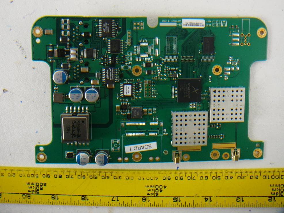
P9J-142402
Nov 14, 2013802.11 b/g/n Radio Module
Equipment Class
DTS - Digital Transmission System