PAQ7000DDRVGA Card
Unitech Electronics Co., Ltd.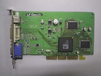
Click to zoom
Application Details
- Equipment Class
- JBP - Part 15 Class B Computing Device Peripheral
- Date of Grant
- Apr 25, 2002
- Application Purpose
- Original Equipment
- Date of Application
- Apr 25, 2002
- Equipment Note
- VGA Card
- Country
- South Korea
Documents & Files
Document Text
Text extracted from the exhibit documents filed with the FCC. Open a document above to read the original.
Users Manual
RADEON ™ 8500/ RADEON 7500 ™ User’s Guide Version 1.0P/N 137-40282-10 Product Notice MACROVISION PRODUCT NOTICE A.Apparatus Claims of U.S. Patent Nos. 4,631,603, 4,577,216, 4,819,098, and 4,907,093 licensed for limited viewing users only. B.In the printed collateral material that accompanies the Product, the following notice must be printed in an appropriate place in such materials: This product incorporates copyright protection technology that is protected by method claims of certain U.S. patents and other intellectual property rights owned by Macrovision Corporation and other rights owners. Use of this copyright protection technology must be authorized by Macrovision Corporation, and is intended for home and other limited viewing uses unless otherwise authorized by Macrovision Corporation. Reverse engineering or disassembly is prohibited. Copyright 2001 by ATI Technologies Inc.: AT Iand RADEON 8500/RADEON 7500 - ATI Technologies Inc.;Windows 98SE, Windows Millennium Edition, Windows NT4.0, Windows 2000 – Microsoft Corp.; VGA – International Business Machines Corp. 2RADEON™ 8500/ RADEON 7500™ User’s Guide Documentation Updates ATI is constantly improving its product and the associated documentation. To maximize the value of your ATI product you should ensure that you have the most up-to-date documentation. ATI’s documentation contains helpful installation/configuration tips and other valuable product feature information. To access the latest documentation for your product visit http://www.ati.com/online/docupdate. RADEON™ 8500/ RADEON 7500™ User’s Guide3 Multiple Monitors Your RADEON 8500/RADEON 7500 provides dual display functionality and TV Out from a single video card. This new technology changes the way you view your PC, TV, and video graphics. The RADEON 8500/RADEON 7500 uses HydraVision™ software to create a seamless multiple display desktop. Multiple monitor display works as one large work area. A single application can span all monitors, or many applications can occupy their own specific monitor. This feature will take your PC’s graphics and video capabilities to the next level. Connecting your RADEON 8500/RADEON 7500 to your monitors The RADEON 8500/RADEON 7500 provides support for one DVI-I monitor or two VGA monitors using the supplied DVI-I- to-VGA adapter. A television can also be used to expand your desktop by using the S-Video connector. Plug the monitor cable into your card(if you are running multiple monitors, connect their cables to the appropriate connectors), then turn on the computer and monitor(s). To connect a flat panel to the RADEON 8500/RADEON 7500 use the DVI-I connector as shown on the following page. To connect a VGA monitor to the DVI-I connector, plug the supplied DVI-I-to-VGA adapter into the DVI-I connector, then plug your monitor cable into the adapter. When you use multiple monitors with your RADEON 8500/RADEON 7500, one monitor will always be primary. Any additional monitor(s) will be designated as secondary. 4RADEON™ 8500/ RADEON 7500™ User’s Guide DISPLAY CABLE TO VGA MONITOR TO DIGITAL/ANALOG DEVICE WITH DVI CONNECTOR DVI-I-TO-VGA ADAPTER DVI-I CONNECTOR VGA CONNECTOR ON CARD FROM MONITOR TO TV/VCR RADEON™ 8500/ RADEON 7500™ User’s Guide5 RADEON 8500/RADEON 7500 Display Configurations Legend: CRT-(cathode ray tube) analog monitor utilizing the standard 15-pin VGA connector DFP-digital flat panel monitor utilizing the 24-pin DVI-I connector - The DVI-I connector can support a monitor using a 15-pin VGA connector via DVI-I-to-VGA adapter - The s-video connector on the board can support a composite connector via s-video-to-composite adapter Display Configuration Connector(s) UsedComments CRT monitor- 15-pin VGA connector - 24-pin DVI-I connector (with DVI-I-to-VGA adapter) DFP monitor- 24-pin DVI-I connector TV- s-video connector CRT monitor + TV - 15-pin VGA connector + s-video connector Unsupported configuration if the CRT monitor is attached to DVI-I connector via DVI-I-to-VGA adapter DFP monitor + TV - 24-pin DVI-I connector + s-video connector CRT monitor + DFP connector - 15-pin VGA connector + 24-pin DVI-I connector CRT monitor + CRT monitor - 15-pin VGA connector + 24-pin DVI-I connector (with DVI-I-to-VGA adapter) CRT monitor + DFP monitor + TV - 15-pin VGA connector + 24-pin DVI-I connector + s-video connector Please note that this will result in two independent displays with the third display “cloning” the image of one of the other two displays. CRT monitor + CRT monitor + TV UNSUPPORTED CONFIGURATION 6RADEON™ 8500/ RADEON 7500™ User’s Guide Multiple Monitor Controls The Windows ® 2000 Multi-Monitor Dialog TheMultiple Monitorcontrol for Windows ® NT4.0/ Windows ® 2000 is found in the Displays tab of the Advanced Settings of the Display Properties. This dialog features a graphic representation of the current monitor array. You can enable and disable monitors by double-clicking on the monitor number in the list box. Multiple Monitor control for Windows ® 98SE and Windows ® Me is located in the Settings tab of the Display Properties. From here, you can enable/disable multiple displays, change color depth and screen resolution. RADEON™ 8500/ RADEON 7500™ User’s Guide7 To enable the secondary display (assuming a secondary display is attached to your RADEON 8500/RADEON 7500): 1 Right-click on monitor labeled“2”. 2 Click“Enable”in the drop-down menu. 3 Click“OK”. The Windows ® 98SE/Windows ® Me Multi-Monitor Dialog To change resolution or color depth: 1 Left-click the desired monitor to make it active. 2 Make the desired changes to the color depth and resolution. To reposition your display, click and drag the appropriate monitor to the desired position. For example, the secondary display can be dragged to the left of the primary display. This allows you to position your secondary display to be either physically left or right of the primary display. 8RADEON™ 8500/ RADEON 7500™ User’s Guide Note The RADEON 8500/RADEON 7500 offers Ratiometric expansi…
Text truncated - open the document above for the full version.
Block Diagram
RV-100 Graphics Controller Specifications© 2000 ATI Technologies Inc. 4-2Proprietary and Confidential Functional Block Diagram 4.1Functional Block Diagram The diagram below shows the major functional blocks of RV-100. DFP CRT Host Bus Interface Concurrent Command Engine 2D Engine iDCT SETUP 3D Renderer PIXEL CACHE MEMORY CONTROLLER 64-BIT SDR/DDR SDRAM/SGRAM Diagnostic & Test Clock Generator DISPLAY FIRST | SECOND AGP/PCI Bus TV mux DIGITAL TMDS TVOUT External Transmitter DAC TMDS Figure 4-1. RV-100 Functional Block Diagram
External Photos
Photos of EuT Model No. : Optimus 7000 DDR Test Report No.:BWS-02-EF-0009 APPENDIX 1 PHOTOs of EUT BWS Tech., Inc. Page Number : 1 of 2 pages http://www.bws.co.kr FCC ID : PAQ7000DDR Issue Date : 04. 23, 2002 Photos of EuT Model No. : Optimus 7000 DDR Test Report No.:BWS-02-EF-0009 A1-1 External Photo of EUT() A1-2 External Photo of EUT(Back) BWS Tech., Inc. Page Number : 2 of 2 pages http://www.bws.co.kr FCC ID : PAQ7000DDR Issue Date : 04. 23, 2002
ID Label/Location Info
ID Label and Location Model No. : Optimus 7000 DDR Test Report No.:BWS-02-EF-0009 APPENDIX 2 ID Label and Location BWS Tech., Inc. Page Number : 1 of 3 pages http://www.bws.co.kr FCC ID : PAQ7000DDR Issue Date : 04. 23, 2002 ID Label and Location Model No. : Optimus 7000 DDR Test Report No.:BWS-02-EF-0009 A2-1 Label Requirements A Class B digital equipment subject to certification by the FCC shall carry a warning label which includes the following statements: This device complies with part 15 of the FCC Rules. Operation is subject to the following two conditions: (1) This device may not cause harmful interference, and (2) this device must accept any interference received, including interference that may cause undesired operation. This statement should be stuck in a conspicuous location on the device. If impossible, this warning label should be placed in a prominent location in the user’s manual. A2-2 Label Drawing : This device complies with part 15 of the FCC rules. Operation is subject to the following conditions: (1) This devices may not cause harmful interference, and (2) this device must accept any interference received including interference that may cause undesired operation. Model No : OPTIMUS 7000 DDR FCC ID : PAQ7000DDR Made in Korea Unitech Electronics Co. Ltd. A2-3 Label Location : Bottom side of EUT BWS Tech., Inc. Page Number : 2 of 3 pages http://www.bws.co.kr FCC ID : PAQ7000DDR Issue Date : 04. 23, 2002 ID Label and Location Model No. : Optimus 7000 DDR Test Report No.:BWS-02-EF-0009 A2-4 Warning Labels Operation manuals for Class B computing devices shall contain the following statements or their equivalent : Note: This equipment has been tested and found to comply with the limits for a Class B digital device, pursuant to part 15 of the FCC Rules. These limits are designed to provide reasonable protection against harmful interference in a residential installation. This equipment generates, uses and can radiate radio frequency energy and, if not installed and used in accordance with the instructions, may cause harmful interference to radio communications. However, there is no guarantee that interference will not occur in a particular installation. If this equipment does cause harmful interference to radio or television reception, which can be determined by turning the equipment off and on, the user is encouraged to try to correct the interference by one or more of the following measures: - Reorient or relocate the receiving antenna. - Increase the separation between the equipment and receiver. - Connect the equipment into an outlet on a circuit different from that to which the receiver is connected. - Consult the dealer or an experienced radio/TV technician for help. y NOTE: You are cautioned that any change or modifications to the equipment not expressly approved by the party responsible for compliance could void your authority to operate such equipment. In case that shielded cables were used on the test, operation manuals shall contain the following statements or their equivalent : y NOTE: This unit was tested with shielded cables on the peripheral devices. Shielded cables must be used with the unit to insure compliance. BWS Tech., Inc. Page Number : 3 of 3 pages http://www.bws.co.kr FCC ID : PAQ7000DDR Issue Date : 04. 23, 2002
Internal Photos
Photos of EuT Model No. : Optimus 7000 DDR Test Report No.:BWS-02-EF-0009 APPENDIX 1 PHOTOs of EUT BWS Tech., Inc. Page Number : 1 of 2 pages http://www.bws.co.kr FCC ID : PAQ7000DDR Issue Date : 04. 23, 2002 Photos of EuT Model No. : Optimus 7000 DDR Test Report No.:BWS-02-EF-0009 A1-1 External Photo of EUT() A1-2 External Photo of EUT(Back) BWS Tech., Inc. Page Number : 2 of 2 pages http://www.bws.co.kr FCC ID : PAQ7000DDR Issue Date : 04. 23, 2002
Test Report
FCC TEST REPORT Model No. : Optimus 7000 DDR Test Report No.:BWS-02-EF-0009 BWS Tech, Inc. 294-9, Jungdae-Dong, Gwangju-City, Gyeoeonggi-Do 464-809 Korea TEL: 82 31 764 0125 FAX: 82 31 764 0126 FCC EMI TEST REPORT Date of Test : Mar. 20 - 21, 2002 Test Report No. : 02BWS009.FCC Test Site : BWS Tech, Inc. (Registration No. : 553281) Trade Name : N/A Manufacturer : Unitech Electronics Co., Ltd. Address : 12#, Cheongjin Bldg., 53-5, Wonhyoro3-Ga, Yongsan-Gu, Korea Contact Person : Sunchoon Park Tel No. : 82-32-574-6600 Fax No. : 82-32-571-0536 Product : VGA CARD Model : OPTIMUS 7000 DDR Fcc Rule Part(s) : FCC Part 15 Subpart B Classification : Class B The device bearing the trade name and model specified above has been shown to comply with the applicable technical standards as indicated in the measurement report and was tested in accordance with the measurement procedures specified in ANSI C.63.4-2000. I attest to the accuracy of data and all measurement reported herein were performed by me or were made under my supervision and are correct to the best of my knowledge and belief. I assume full responsibility for the completeness of these measurements and vouch for the qualification of all persons taking them. 2002. 04.04 TaeHyun Nam President-BWS Tech, Inc. BWS Tech., Inc. Page Number : 1 of 1 pages http://www.bws.co.kr FCC ID : PAQ7000DDR Issue Date : 04. 23, 2002 FCC TEST REPORT Model No. : Optimus 7000 DDR Test Report No.:BWS-02-EF-0009 TABLE OF CONTENTS PAGE 1. Description of device 3 1.1 General 3 1.2 EUT Description 3 2. Test facility 4 3. Summary of results 4 3.1 Electromagnetic Emission 4 3.2 Modifications to the EUT 4 4. Tested system details 5 4.1 Peripherals and Others 5 4.2 Type of Cables Used 5 4.3 System layout on EUT and peripherals 6 5. Test result 7 5.1 RFI Voltage Measurement 7 5.2 RFI Field Strength Measurement 9 5.3 Minimum Margin 13 5.4 Sample Calculations 13 6. Test Equipments ---------------------------------------------------- 14 BWS Tech., Inc. Page Number : 2 of 2 pages http://www.bws.co.kr FCC ID : PAQ7000DDR Issue Date : 04. 23, 2002 FCC TEST REPORT Model No. : Optimus 7000 DDR Test Report No.:BWS-02-EF-0009 1. DESCRIPTION OF DEVICE 1.1 General Responsible Party Unitech Electronics Co., Ltd. Contact Person Sunchoon Park Tel No. : 82-32-574-6600 Fax No. : 82-32-571-0536 Manufacturer Unitech Electronics Co., Ltd. 12#, Cheongjin Bldg., 53-5, Wonhyoro3-Ga, Yongsan-Gu, Korea • Trade name N/A • Model name OPTIMUS 7000 DDR • EUT Type VGA CARD • Classification FCC Part 15 Subpart B Class B • Clock Speed 27 MHz • Rule Part(s) FCC Part 15 & Part 2 • Test Procedure(s) ANSI C63.4-2000 • Date of Tests Mar. 20 - 21, 2002 • Place of Tests BWS Tech, Inc. 1.2 EUT Description 5 Note. This report may be reproduced in full. Partial reproduction may only be made with the written permission of the laboratory. The results in this report is only applied to the sample(s) tested. 5 Note. Please refer to the duties and responsibilities of the Responsible Party attached. BWS Tech., Inc. Page Number : 3 of 3 pages http://www.bws.co.kr FCC ID : PAQ7000DDR Issue Date : 04. 23, 2002 FCC TEST REPORT Model No. : Optimus 7000 DDR Test Report No.:BWS-02-EF-0009 2. TEST FACILITY The open field test site and conducted measurement facility used for this measurement, is located following address. This site was fully described in a report dated Dec. 26, 2001 that was submitted to the FCC. Our site and facility had been accepted in a letter dated Dec. 26, 2001(Registration No. : 553281) : BWS Tech, Inc. Address : 294-9, Jungdae-Dong, Gwangju-City, Gyeonggi-Do 464-080 Korea The detailed description of the measurement facility was found to be in compliance with the requirements of 2.948 according to ANSI C63.4 on Dec. 08, 2000. 3. SUMMARY OF RESULTS 3.1 Electromagnetic Emission RFI Voltage Measurement PASS RFI Field Strength Measurement PASS Although the measured emissions indicate that the EUT complies with the required limits, some measurement are close to these limits. When the uncertainty of measurement is considered, there is some possibility that the EUT may not be compliant. 3.2 Modifications to the EUT : None BWS Tech., Inc. Page Number : 4 of 4 pages http://www.bws.co.kr FCC ID : PAQ7000DDR Issue Date : 04. 23, 2002 FCC TEST REPORT Model No. : Optimus 7000 DDR Test Report No.:BWS-02-EF-0009 4. TESTED SYSTEM DETAILS 4.1 Peripherals and Others : Description Model Name Serial No. Manufacturer FCC ID Computer KAYAK 5064-7432A034598 HP DoC PS2 Mouse M-S34 F13490N5BGF Compaq DZL211029 Serial Mouse #1 OK-520 00DAC0231 A4 TECH DoC Serial Mouse #2 Pro Mouse II 96002117 NEOTEC FSUGMZC7 Modem 0775 - 3Com Corporation - Joystick GAMEPAD USB S1050910000564 CREATIVE DoC Keyboard RT235BTW B13BC90L39GU Compaq AQ6-22K15 Monitor 77E P193H1DR201480 Samsung - Monitor VX700 M902080938 Gateway BGBTFV8705K CCTV SAM-14M 970610528 Samsung - EUT OPTIMUS 7000 DDR - Unitech Electronics Co., Ltd. EUT 4.2 Type of Cables Used: Device from Device to Type of Cable Length Type of shield Computer Keyboard Signal cable 1.0 Shielded Computer PS2 Mouse Signal cable 1.0 Shielded Computer Mouse #1, #2 Signal cable 1.0 Shielded Computer Joystick Signal cable 1.2 Shielded Computer Modem Signal cable 1.2 Shielded Power Cable Power - 1.5 Unshielded EuT Video Monitor Signal cable 1.0 Shielded EuT DVI Monitor Signal cable 1.0 Shielded EuT S-Video CCTV Signal cable 1.2 Shielded BWS Tech., Inc. Page Number : 5 of 5 pages http://www.bws.co.kr FCC ID : PAQ7000DDR Issue Date : 04. 23, 2002 FCC TEST REPORT Model No. : Optimus 7000 DDR Test Report No.:BWS-02-EF-0009 BWS Tech., Inc. Page Number : 6 of 6 pages http://www.bws.co.kr FCC ID : PAQ7000DDR Issue Date : 04. 23, 2002 4.3 System layout on EUT and peripherals Monitor Monitor CCTV PC E U T E u T MouseModem Joystick Keyboard MouseMouse <Figure 4-1 System layout> FCC TEST REPORT Model No. : Optimus 7000 DDR Test Report No.:BWS-02-EF-0009 5. TEST RESULT 5.1 RFI Voltage Measurement 5.1.1 Measurement I…
Text truncated - open the document above for the full version.
Test Setup Photos
TEST SET UP PHOTOS Model No. : Optimus 7000 DDR Test Report No.:BWS-02-EF-0009 APPENDIX 3 TEST SET UP PHOTOS BWS Tech., Inc. Page Number : 1 of 2 pages http://www.bws.co.kr FCC ID : PAQ7000DDR Issue Date : 04. 23, 2002 TEST SET UP PHOTOS Model No. : Optimus 7000 DDR Test Report No.:BWS-02-EF-0009 A3-1. Setup with the Maximized RFI Voltage Emission Level 7.2 Setup with the Maximized RFI Field Strength Emission Level BWS Tech., Inc. Page Number : 2 of 2 pages http://www.bws.co.kr FCC ID : PAQ7000DDR Issue Date : 04. 23, 2002
Contact Information
Applicant
Byung-Cheol Yoo(Manager)
Test Firm
BWS TECH INCCheol-Ho Lee
Technical Specifications
| # | Rule Parts | Frequency Range | Power Output |
|---|---|---|---|
| 1 | 15B | - | - |
Other Applications from Unitech Electronics Co., Ltd.
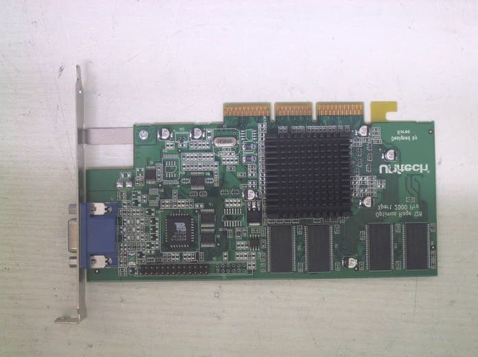
PAQXPERT2000
Jul 08, 2003VGA CARD
Equipment Class
JBP - Part 15 Class B Computing Device Peripheral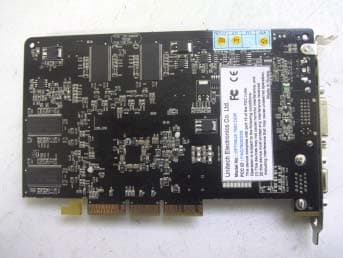
PAQOPT7500LE
Jul 21, 2002VGA Card
Equipment Class
JBP - Part 15 Class B Computing Device Peripheral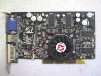
PAQOPT9000PRO
Jul 11, 2002VGA Card
Equipment Class
JBP - Part 15 Class B Computing Device Peripheral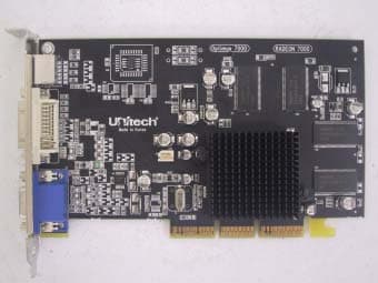
PAQOPTIMUS7000
Jun 17, 2002VGA Card
Equipment Class
JBP - Part 15 Class B Computing Device Peripheral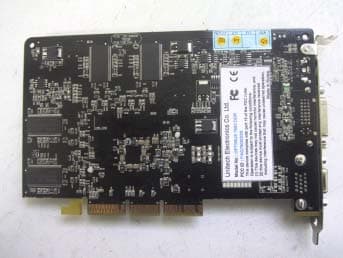
PAQ7500DDR
May 08, 2002VGA Card
Equipment Class
JBP - Part 15 Class B Computing Device Peripheral