PAV-IMIC2020USB Audio Computer Add-On
Griffin Technology Inc.
Click to zoom
Application Details
- Equipment Class
- JBP - Part 15 Class B Computing Device Peripheral
- Date of Grant
- Jan 31, 2001
- Application Purpose
- Original Equipment
- Date of Application
- Jan 31, 2001
- Equipment Note
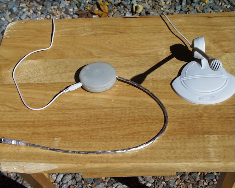
- USB Audio Computer Add-On
- Company
- Griffin Technology Inc.
- Country
- United States
Documents & Files
Document Text
Text extracted from the exhibit documents filed with the FCC. Open a document above to read the original.
Block Diagram
1234 A B C D 4321 D C B A Title NumberRevisionSize A4 Date:21-Dec-2000Sheet of File:D:\TR\iMicBlock.ddbDrawn By: ADC and DAC to and from USB Controller USB Macintoch or PC Computer Input Audio Amplifier Line Level Audio Output Line or Mic Level Select User Actuated Switch Audio Signal In Audio Signal Out iMic Block Diagram iMic1500A 1 of 1 R. Riffert Switch iMic
Test Report
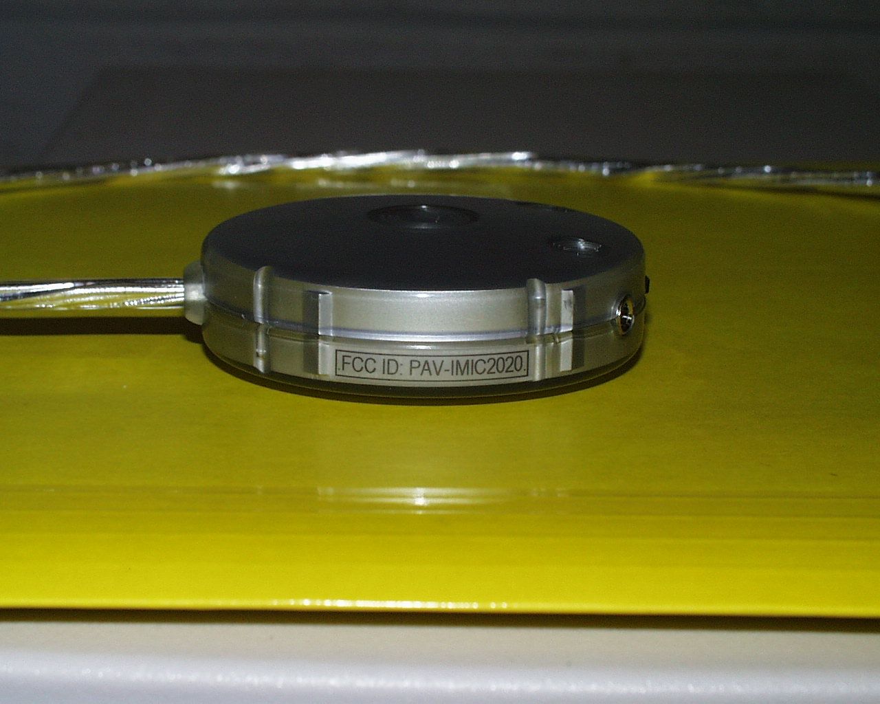
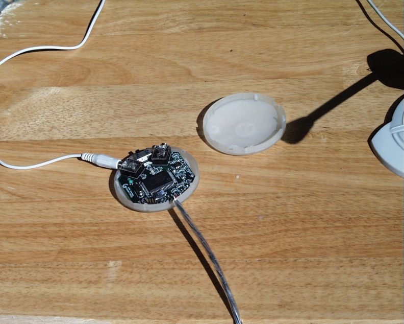
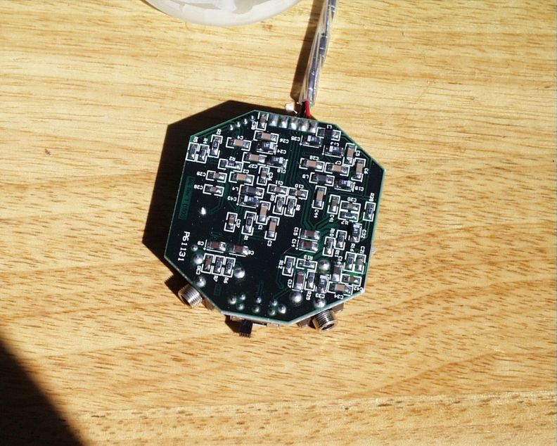
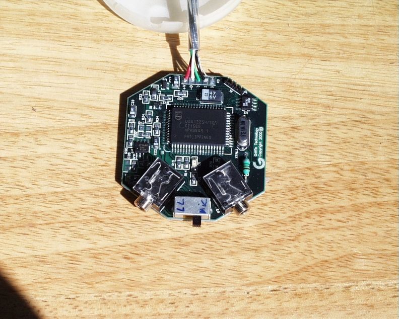
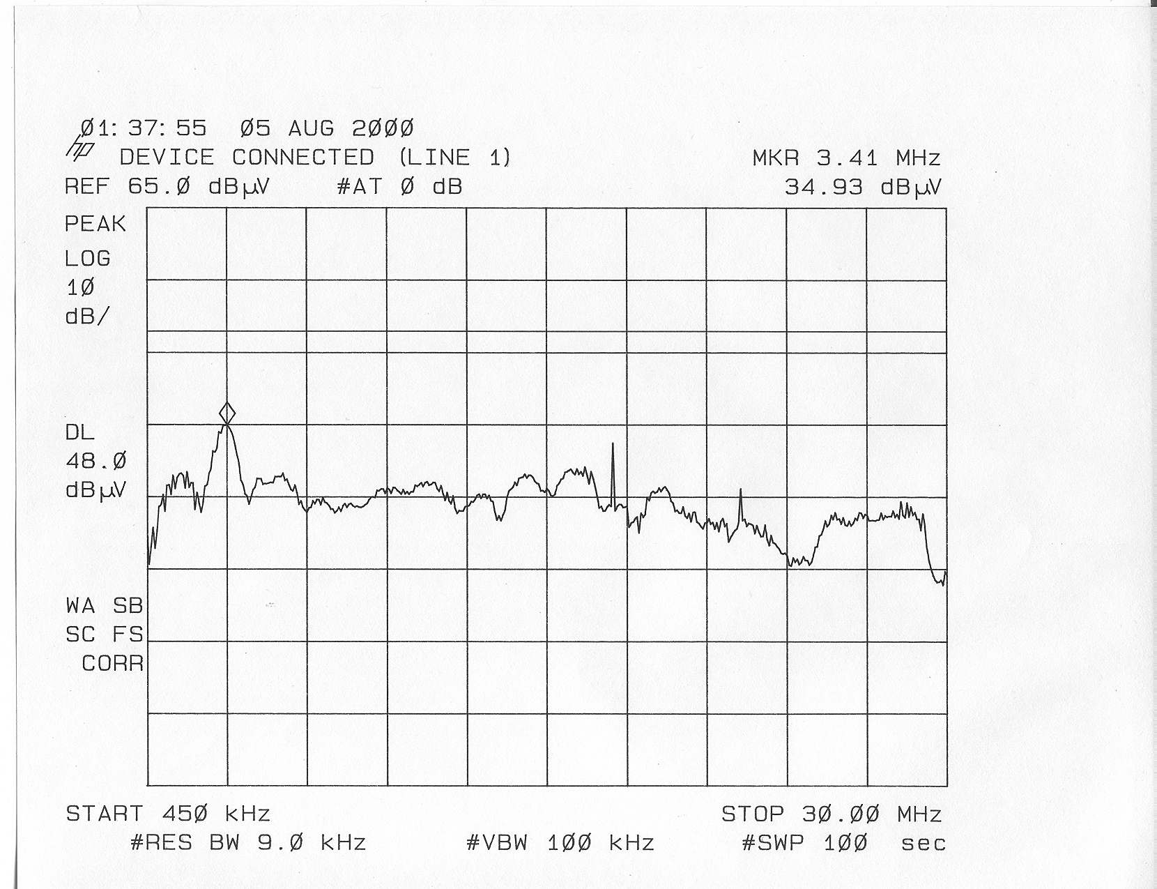
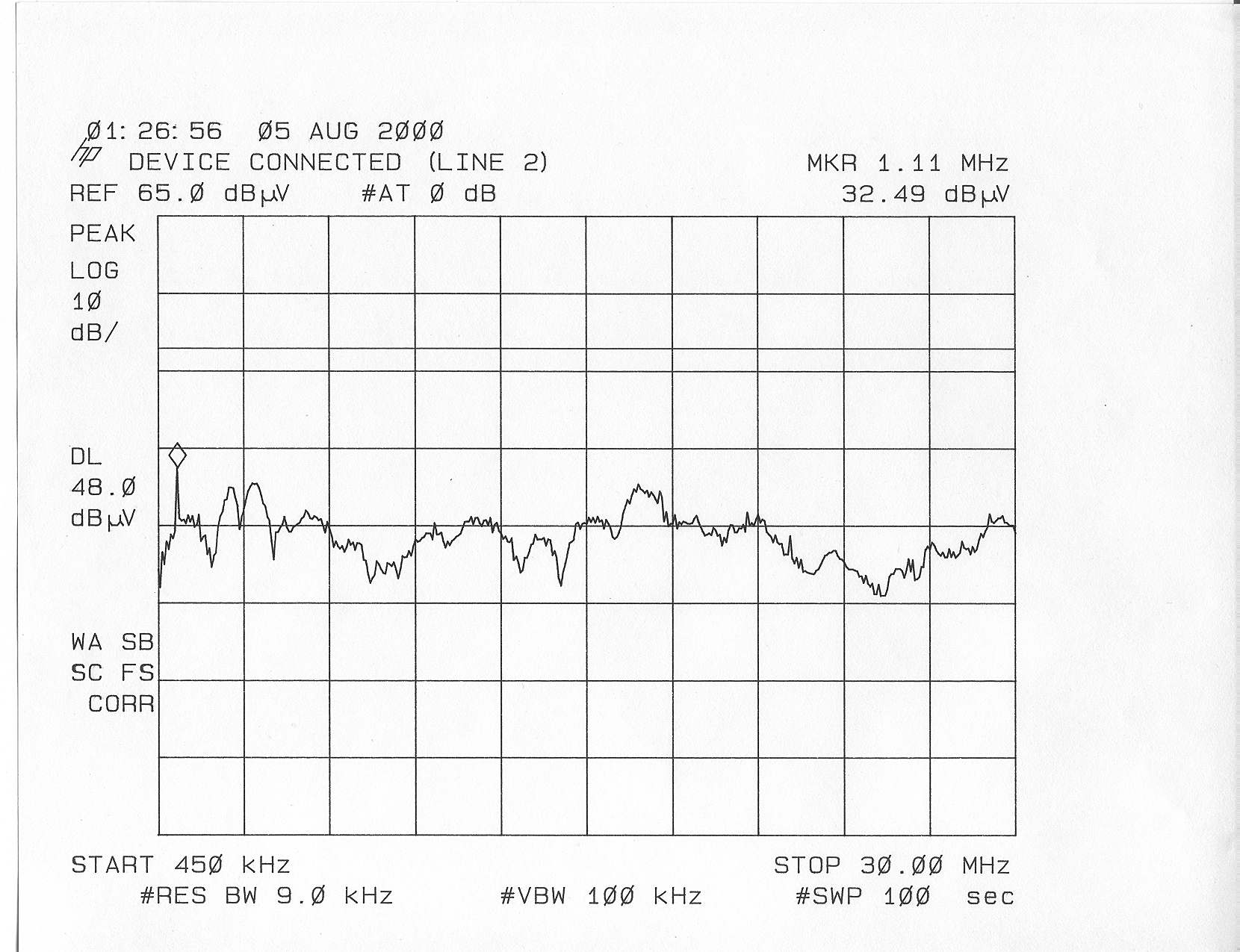
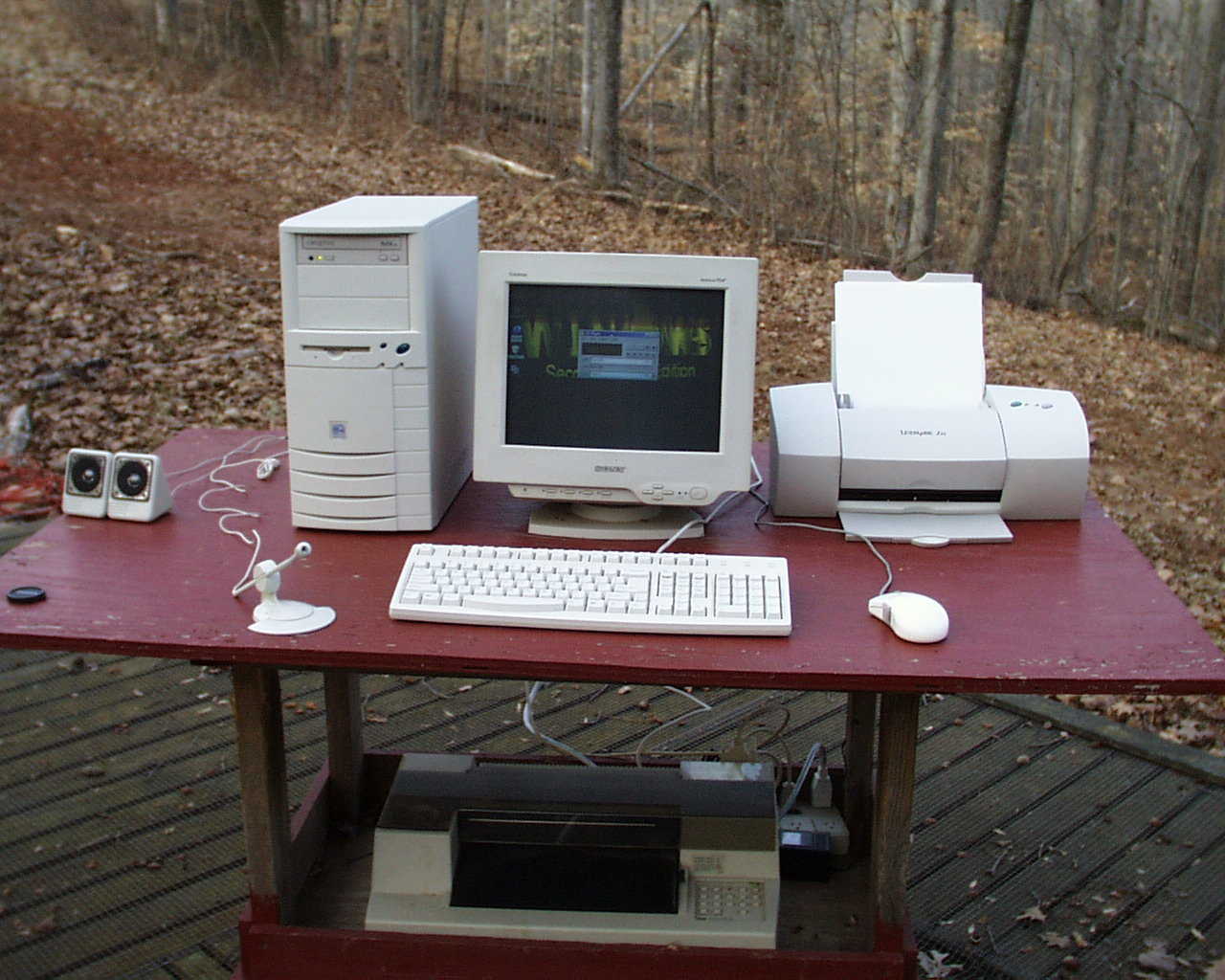
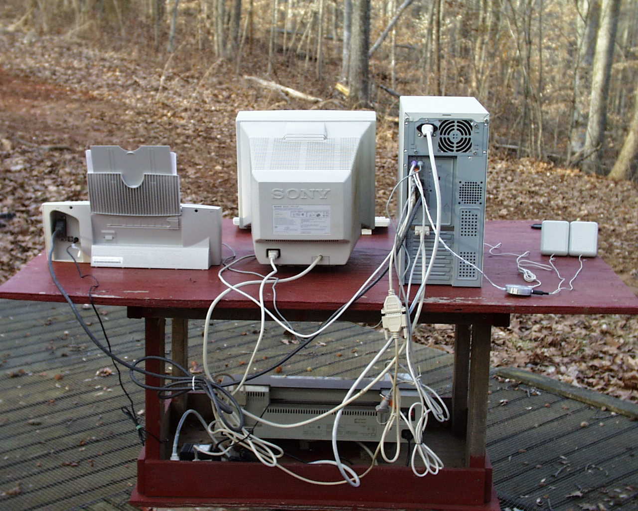
1 CD&T FCC ID: PAV-IMIC2020 A. DEVICE UNDER TEST The device is a USB connectable computer peripheral device for converting audio signals into digital code and to reconvert digital coded audio back to analog. The device is powered from the computer through the 5 volt supply line of a USB port and is internally regulated down to 3.3 volts. The device is configured around a Philips UDA1325H USB codec clocked at 48 MHz. with an on board crystal. This device does not operate as a stand alone product. B. MEASUREMENT PROCEDURE: RADIATED EMISSIONS Testing of this device was conducted at the Hyak Laboratories facility in Spotsylvania, Virginia. Field strength measurements were conducted according to the procedures set forth in ANSI C63.4 (1992). The device was connected to a current production desktop computer system and placed on a rotating turntable 0.8 meters high, centered at 3 meters distant from the measurement antenna. The device was positioned in the center of the turntable and tested as shown in the photographs. Interconnections between the test computer and the device were arranged to yield the maximum level of emissions. The field strength measurements were taken using an HP8596E spectrum analyzer, a Compliance Design biconical antenna set and an Avantek UJ210 preamp. The device was scanned from 30MHz. to 1GHz. and all emissions were noted. During the test, the device was periodically disconnected from the test computer in order to separate out the emissions that were emanating from the computer and to determine if any emissions generated by the computer were increased by the presence of the device. 2 At each detected frequency of emission, the device was measured by rotating the turntable and adjusting the antenna height over a range of 1 to 4 meters to obtain the maximum output level. This procedure was performed with both horizontal and vertical antenna polarizations with the device placed in the position described above. The peak reading for each frequency was recorded. The readings and calculated field strength appear in Table 1. C. MEASUREMENT PROCEDURE: CONDUCTED EMISSIONS Line conducted measurements were taken using an HP8591E spectrum analyzer and a Compliance Design LISN. Scans were run from 450KHz to 30MHz and plotted on an HP7475A pen plotter. Peaks are identified with markers. To determine the contribution by the device to the overall conducted emissions; a separate set of plots was taken to record the conducted levels generated by the test computer. These plots are identified as “computer ambient”. continued on page 3 RADIATED EMISSIONS CFR V47 15.109(a) Ant. H/V Duty cycle dB Adjusted power uV/m@3m FCC limit uV/m3m 31.530V9.8-97.0610100 33.351V9.7-98.228100 35.032V9.4-99.817100 48.000H10.3-84.1745100 48.330V10.3-92.7317100 52.721H10.6-91.0721100 57.113H10.4-90.8421100 60.050H10.1-86.3335100 61.443V9.6-86.6032100 64.004V9.1-84.7837100 65.880H8.5-83.9938100 66.650H8.1-96.149100 68.004V7.6-92.4013100 70.268H7.1-89.2318100 72.004H6.6-85.9424100 Frequency MHz. Peak power uV/m@3m Table 1 FCC ID: PAV-IMIC2020 MODEL: IMIC-1500 TEST DATE: 29-JAN-01 Peak reading dBm Ant. Factor dB ANTENNA: BICONICALS 3 Ant. H/V Duty cycle dB Adjusted power uV/m@3m FCC limit uV/m3m 73.725H6.3-90.2614100 83.258H6.8-90.0315100 87.758H8.4-86.2229100 90.981H9.5-91.3618150 96.000H10.4-90.7122150 98.302H10.6-92.1319150 100.086H10.9-97.4311150 104.448H11.6-93.3818150 109.767H12.7-95.8116150 118.546H12.6-92.7322150 120.099H12.5-92.0624150 128.006H12.3-93.4220150 131.760H12.4-94.5417150 144.001H12.8-92.6723150 147.450H12.9-95.9016150 153.802H13.7-98.0314150 159.336H15.2-96.5519150 163.540H16.2-99.4815150 168.001V17.3-98.1020150 173.413V18.2-99.7119150 181.207V15.6-97.4518150 240.005H19.0-102.4715200 288.007H22.1-98.7833200 336.005H23.5-99.0337200 384.008H23.8-96.1154200 432.009H25.1-101.0336200 480.010H26.0-99.3448200 492.006V26.1-101.7837200 528.011V26.9-102.7336200 533.117H27.7-105.9527200 576.011V28.3-102.4044200 624.012V28.6-105.2933200 672.014V29.0-108.5124200 720.014V29.6-110.3521200 768.016 V 30.3-109.2425200 788.916H30.5-114.8414200 816.017H30.7-112.9917200 864.019H31.1-119.828200 877.583H31.3-116.5812200 879.750H31.3-119.269200 Table 1 cont. Frequency MHz. Ant. Factor dB Peak reading dBm Peak power uV/m@3m
Contact Information
Applicant
Michael OConnor(Compliance Manager)
Test Firm
Hyak Laboratories, Inc.Rowland Johnson
703-451-1188
Technical Specifications
| # | Rule Parts | Frequency Range | Power Output |
|---|---|---|---|
| 1 | 15B | - | - |
Other Applications from Griffin Technology Inc.
PAV36210
Dec 11, 2013Low Power FM Transmitter
Equipment Class
DXT - Part 15 Low Power Transceiver, Rx Verified
PAV1131I
Jun 09, 2013Low Power FM transmitter
Equipment Class
DXT - Part 15 Low Power Transceiver, Rx Verified
PAV36237
Oct 29, 2012MOD-36237 Moto TC Racer
Equipment Class
DXX - Part 15 Low Power Communication Device Transmitter
PAV100-4077
Apr 07, 2011Bluetooth Module
Equipment Class
DSS - Part 15 Spread Spectrum Transmitter
PAV1131
Oct 31, 2010Portable FM Transmitter
Equipment Class
DXT - Part 15 Low Power Transceiver, Rx Verified