PAV4015TRIPLow Power FM Transmitter
Griffin Technology Inc.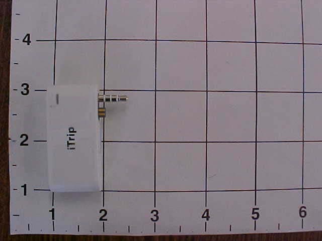
Click to zoom
Application Details
- Equipment Class
- DXX - Part 15 Low Power Communication Device Transmitter
- Date of Grant
- Aug 04, 2004
- Application Purpose
- Original Equipment
- Date of Application
- Jun 14, 2004
- Equipment Note
- Low Power FM Transmitter
- Frequency Range
- 88.10000000 - 107.70000000
- Company
- Griffin Technology Inc.
- Country
- United States
Documents & Files
Document Text
Text extracted from the exhibit documents filed with the FCC. Open a document above to read the original.
Users Manual
MANUAL Thank you for purchasing the iTrip , the only wireless FM transmitter made specifically for the iPod. Now you can play your music in your car or anywhere there's an FM radio. We'll have you up and running in three easy steps. iTRIP QUICK START (Mac) Insert the included iTrip CD-Rom into your Mac. Launch and run the iTrip Installer. A ll necessary files ar e now installed into iTunes. Connect and sync your iPod with iTunes. This will tr ansfer the newly created iTrip Stations playlist and files into your iPod. Properly disconnect the Fir eWir e cable and firmly attach the iTrip into the headphone jack of the iPod. Pla ying music through the iTrip automatically turns the iTrip on. The LED will blink as it's powering up. The iTrip is preset to 87.9 on your FM radio. To select your own station, f ollow the instructions that continue inside this booklet. 1 2 3 iTRIP QUICK START (PC) Insert the included iTrip CD-Rom into your PC. The iTrip Installer should begin automatically. I f this does not happen, simply run the Setup.EXE file located on the iTrip CD-Rom. This will install all necessary files into MusicMatch or iTunes. Connect and sync your iPod with MusicMatch or iTunes. This will transfer the newly created iTrip Stations playlist and files into your iPod. Properly disconnect the Fir eWir e cable and firmly attach the iTrip into the headphone jack of the iPod. P la ying music through the iTrip automatically turns the iTrip on. The LED will blink as it's powering up. The iTrip is preset to 87.9 on your FM radio. To select your own station, f ollow the instructions that continue inside this booklet. 1 2 3 1 2 3 CHOOSING A NEW BROADCAST FREQUENCY Navigate to the iTrip Stations playlist installed on your iPod. Highlight the chosen frequency and click the PLAY/PAUSE ( ) button. When the LED begins to rapidly blink, click the PLAY/PAUSE ( ) button once again. The LED light will pulse three times slowly to confirm the iTrip has changed its frequency successfully. NOTES & TIPS: The volume of your iPod needs to be between 40% - 80% for the iTrip frequency change to work correctly. Check and adjust this first bef ore att empting a change. You can change frequencies as many times as you want. You may also discar d any iT rip stations you currently don't need. The whole collection will always be available on the iTrip CD-Rom and online. The iTrip can broadcast to any spot on your FM radio. Scan the FM stations to find an empty frequency. Then follow these simple st eps to set your iTrip to broadcast to that selected frequency. PLAY/PAUSE ( ) button 1 2 TURNING THE LED ‘OFF’ OR ‘ON’ To turn the status LED on the front of the iTrip OFF, navigate to the bottom of the iTrip Stations playlist and select “LED off”. Then follow these two simple steps. Click the PLAY/PAUSE ( ) button on your iPod. When the LED begins to rapidly blink, click the PLAY/PAUSE ( ) button again. The LED will pulse three times slowly to confirm. The LED will remain off until you change frequencies. I t will turn on to give you visual feedback during the procedure, and then turn off again. To turn the status LED on, select “LED on” at the bottom of the iTrip Stations playlist, and follow the two steps listed above. TURNING THE iTRIP OFF The iTrip never needs to be turned off. I t turns off automatically if no music is present for 60 seconds. I t turns back on when any music comes from the iPod. CHARGING YOUR iPOD WHILE USING THE iTRIP (Original iPod) To charge your iPod while your iTrip is in use, simply lift and rotate the iTrip a quarter turn counter-clockwise. R e-connect the iTrip perpendicular to the iPod by pushing down until the LED comes on. This exposes the Fir eWir e port for charging. iTRIP TROUBLESHOOTING The iTrip won’t wake up from sleep. The iTrip automatically wakes from sleep when music is played into it. The first thing to check is that you're playing sufficiently loud music into your iTrip . When the iTrip begins to wake from sleep, it can take sever al seconds, depending on its set frequency. The higher the frequency, the longer the iTrip takes. S o if you have iTrip tuned to 107.9 it may take a while. B ut be patient - it will come on. If your iTrip is still not responding, disconnect then reconnect the iTrip . P ush down firmly to make sure it’s solidly connected to the iPod. Pla ying music through the iTrip should now wake it from sleep. How do I get the best sound quality when using the iTrip? The iTrip works best when tuned to the clearest frequency possible. For the best performance, make sure the frequency you choose doesn’t have a strong radio station close to it. Also, there is definitely a 'sweet spot' volume setting on the iPod that achieves the best sound quality through the iTrip . That spot will vary depending on the audio being played. B egin by setting the volume at 50%, then slowly increasing until you get the best balance of signal clarit y without sound distortion. For more tips and tricks to help you get the most out of your iTrip , please visit Griffin online support at http://www.griffintechnology.c om/support iTRIP TECHNICAL SPECIFICATIONS • Dimensions: 2.4" x .84" • Built-in antenna • Power Requirement: iPod connection • Modulation: FM Ster eo • Frequencies: 87.9 - 107.9 MHz • High stability crystal oscillator , phase-lock loop contr ol • Ster eo separation: greater than 45 dB • Signal distortion: less than .5% • Frequency response: 50 Hz to 15 kHz • Oper ating range: 10-30 ft (limited by FCC regulations) • International frequencies softwar e selectable • FCC compliant (FCC PAV4014TRIP) This device complies with Part 15 of the FCC Rules. Oper ation is subject to the following two conditions: (1) this device may not cause harmful interfer ence, and (2) this device must accept any interfer ence received, including interfer ence that may cause undesired oper ation. CAUTION: C hanges or modifications not expressly approved by the party responsible for compliance could void the user's a…
Text truncated - open the document above for the full version.
External Photos
1.1 Photograph of EUT EUT: MINI ITRIP View: External Top, (Antenna) External Front Wire Antenna
ID Label/Location Info
1.1 Label
Internal Photos
1.1 Photograph of EUT EUT: MINI ITRIP View: Internal Side 1 Internal Side 2 internal chassis and antenna routing Wire Antenna
Operational Description
1.1 Equipment Description If you have an iPod mini you need an iTrip mini. The iTrip mini FM transmitter lets you play your iPod mini’s music wirelessly through any FM radio — in your car, on the road, even at home through your stereo. The iTrip mini was designed exclusively for the iPod mini. Its form factor matches perfectly all the curves and lines of the iPod mini. It sounds even sweeter. iTrip mini gives you the best possible performance because you can choose any empty station from 87.7 to 107.9. Best of all you choose and change your iTrip mini stations directly from the iPod mini itself. The iTrip mini does NOT need batteries. It receives a tiny amount of power directly from the iPod mini – saving you from wasting hundreds of batteries a year. That’s good news for the planet and even better news for your wallet. The iTrip mini can even be used while charging your iPod mini in your car or while docked. If you add our PowerPod iPod auto charger you can listen to your iPod mini while road tripping all the way across America. Now that’s cool! iTrip mini doesn’t have a power switch - it doesn't need one. Just plug it in and go. It shuts off automatically after 60 seconds of silence just like the iPod mini. You see, we designed the iTrip mini to be the ultimate iPod mini accessory because it lets you share the music and share the fun. Forget the headphones. Get an iTrip mini and go wireless!
Test Report
REPORT #46073F Transmitter Certification Report Per CFR 47 Part 15 Section 15.239 EUT: Mini iTrip NVLAP Lab Code 200634-0 PREPARED FOR APPLICANT: Griffin Technology 1619C Elm Hill Pike Suite C Nashville, TN 37210 REPORT # 46073F Test Completion Date: June 8, 2004 Prepared By: DNB ENGINEERING, INC. 1100 East Chalk Creek Rd. Coalville, Utah 84017 Tel: 1(435) 336-4433 REPORT #46073F EXECUTIVE SUMMARY The purpose of this series of tests was to demonstrate the Electromagnetic Compatibility (EMC) characteristics of the MINI ITRIP, the following tests were performed: REQUIREMENTS STATUS COMPLIANT Yes/No/NA 47 CFR Part 15 Subpart C, ITE Emissions Yes Radiated Emissions Section 15.239 Yes Signed By : Clay Allred Lab Manager DNB Engineering Inc. This report shall not be reproduced without the written approval of DNB ENGINEERING, INC. Results contained in this report relate only to the item tested. 2 REPORT #46073F DOCUMENT HISTORY Revision Letter Number of Pages Page No. of Rev. Description Date 52 Document Release 06/17/2004 3 REPORT #46073F TABLE OF CONTENTS 1 INTRODUCTION..............................................................................................................................................8 1.1 ADMINISTRATIVE DATA AND TEST DESCRIPTION.....................................................................................8 1.2 TEST CONFIGURATION...............................................................................................................................8 1.3 EQUIPMENT DESCRIPTION..........................................................................................................................8 1.4 MODE OF OPERATION.................................................................................................................................8 1.5 DOCUMENTED EMC CONTROL MEASURES...............................................................................................8 1.6 CLOCK FREQUENCIES.................................................................................................................................9 1.7 TEST VOLTAGE...........................................................................................................................................9 1.8 DEVIATIONS...............................................................................................................................................9 1.9 JUSTIFICATIONS..........................................................................................................................................9 1.10 BLOCK DIAGRAM.......................................................................................................................................9 1.11 LABEL.......................................................................................................................................................10 1.12 PHOTOGRAPH OF EUT..............................................................................................................................11 1.13 PHOTOGRAPH OF EUT..............................................................................................................................12 2 SPURIOUS EMISSIONS FCC PART 15, CLASS B......................................................................................13 2.1 RADIATED EMISSIONS TEST SETUP AND PROCEDURE.............................................................................13 2.1 RADIATED SPURIOUS EMISSIONS COMPLIANCE DATA............................................................................15 2.2 FUNDAMENTAL FREQUENCY EMISSIONS DATA.......................................................................................16 2.3 CLIMATIC CONDITIONS............................................................................................................................17 2.4 COMPLIANT STATEMENT..........................................................................................................................17 2.5 TEST DATA TRANSMITTING AT 88.3 MHZ (LOWER TRANSMIT FREQUENCY).........................................18 2.5.1 88.3 MHz Fundamental Frequency Emissions Test Data................................................................18 2.5.2 Spurious Emissions Test Data..........................................................................................................19 2.5.3 30-300 MHz Horizontal...................................................................................................................20 2.5.4 300-1000 MHz Horizontal...............................................................................................................21 2.5.5 30-300 MHz Vertical.......................................................................................................................22 2.5.6 300-1000 MHz Vertical...................................................................................................................23 2.6 TRANSMITTING AT 98.3 MHZ (MIDDLE TRANSMIT FREQUENCY)...........................................................24 2.6.1 98.3 MHz Fundamental Frequency Emissions Test Data................................................................24 2.6.2 Spurious Emissions Test Data..........................................................................................................25 2.6.3 30-300 MHz Horizontal...................................................................................................................26 2.6.4 300-1000 MHz Horizontal...............................................................................................................27 2.6.5 30-300 MHz Vertical.......................................................................................................................28 2.6.6 300-1000 MHz Vertical...................................................................................................................29 2.7 TRANSMITTING AT 107.7 MHZ (UPPER TRANSMIT FREQUENCY)...........................…
Text truncated - open the document above for the full version.
Test Report
1.1 Test Data Transmitting at 88.3 MHz (lower Transmit Frequency) 1.1.1 88.3 MHz Fundamental Frequency Emissions Test Data 1.1.2 Spurious Emissions Test Data 1.1.3 30-300 MHz Horizontal 1.1.4 300-1000 MHz Horizontal 1.1.5 30-300 MHz Vertical 1.1.6 300-1000 MHz Vertical 1.2 Transmitting at 98.3 MHz (Middle Transmit Frequency) 1.2.1 98.3 MHz Fundamental Frequency Emissions Test Data 1.2.2 Spurious Emissions Test Data 1.2.3 30-300 MHz Horizontal 1.2.4 300-1000 MHz Horizontal 1.2.5 30-300 MHz Vertical 1.2.6 300-1000 MHz Vertical 1.3 Transmitting at 107.7 MHz (Upper Transmit Frequency) 1.3.1 107.7 MHz Fundamental Frequency Emissions Test Data 1.3.2 Spurious Emissions Test Data 1.3.3 30-300 MHz Horizontal 1.3.4 300-1000 MHz Horizontal 1.3.5 30-300 MHz Vertical 1.3.6 300-1000 MHz Vertical
Test Setup Photos
1.1 Photograph of Radiated Emissions Test Setup EUT: MINI ITRIP View: Test Setup
Contact Information
Applicant
Michael OConnor(Compliance Manager)
Technical Contact
DNB Engineering, Inc.Clay Allred
[email protected]435-336-4433
1100 East Chalk Creek RD · Coalville, Utah · USA Minor Outlying Islands
Non-Technical Contact
DNB Engineering Inc.Clarice Yates
[email protected]435-336-4433
Test Firm
DNB Engineering, Inc.Clay Allred
Technical Specifications
| # | Rule Parts | Frequency Range | Power Output |
|---|---|---|---|
| 1 | 15C | 88.1 MHz - 107.7 MHz | - |
Other Applications from Griffin Technology Inc.
PAV36210
Dec 11, 2013Low Power FM Transmitter
Equipment Class
DXT - Part 15 Low Power Transceiver, Rx Verified
PAV1131I
Jun 09, 2013Low Power FM transmitter
Equipment Class
DXT - Part 15 Low Power Transceiver, Rx Verified
PAV36237
Oct 29, 2012MOD-36237 Moto TC Racer
Equipment Class
DXX - Part 15 Low Power Communication Device Transmitter
PAV100-4077
Apr 07, 2011Bluetooth Module
Equipment Class
DSS - Part 15 Spread Spectrum Transmitter
PAV1131
Oct 31, 2010Portable FM Transmitter
Equipment Class
DXT - Part 15 Low Power Transceiver, Rx Verified