PAXPMV107LLow Power Transmitter for monitoring tire pressure
Pacific Industrial Company, LTD.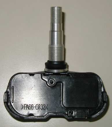
Click to zoom
Application Details
- Equipment Class
- DXX - Part 15 Low Power Communication Device Transmitter
- Date of Grant
- Feb 06, 2006
- Application Purpose
- Original Equipment
- Date of Application
- Feb 06, 2006
- Equipment Note
- Low Power Transmitter for monitoring tire pressure
- Frequency Range
- 314.94000000 - 314.94000000
- Country
- Japan
Documents & Files
Document Text
Text extracted from the exhibit documents filed with the FCC. Open a document above to read the original.
Block Diagram
7/8 5. Marking location and layout Fig 5. Marking location and dimension 6. Block diagram Fig 6, Block diagram of transmitter Temperature sensor Motion sensor Voltage sampling ID Digital process Battery antenna Custom IC Pressure sensor SAW resonator Oscillation circuit Matching circuit Notes: Compliance statement of marking will not be changed. But marking layout and size may be changed. 315MH Digital modulation Base band IQ 314.55MHz
External Photos
Top view of Transmitter 2/4 Bottom view of Transmitter Front view of Transmitter 3/4 Rear view of Transmitter Right side view of Transmitter Left side view of Transmitter
ID Label/Location Info
7/8 5. Marking location and layout Fig 5. Marking location and dimension 6. Block diagram Fig 6, Block diagram of transmitter Temperature sensor Motion sensor Voltage sampling ID Digital process Battery antenna Custom IC Pressure sensor SAW resonator Oscillation circuit Matching circuit Notes: Compliance statement of marking will not be changed. But marking layout and size may be changed. 315MH Digital modulation Base band IQ 314.55MHz
Internal Photos
4/4 Internal photos Antenna
Test Report
A-017-05-C Page 1 of 19 FCC ID: PAXPMV107L KEC Ikoma Testing Laboratory 12128 Takayama-cho Ikoma-city Nara 630-0101 Japan KANSAI ELECTRONIC INDUSTRY DEVELOPMENT CENTER HEAD OFFICE IKOMA TESTING LABORATORY 6-8-7 NISHITENMA 12128 TAKAYAMA-CHO KITA-KU OSAKA 530-0047 JAPAN IKOMA-CITY NARA 630-0101 JAPAN Corporate Juridical Person TEST REPORT Report No.A-017-05-C Date: 27 December 2005 This test report is to certify that the tested device properly complies with the requirements of: FCC Rules and Regulations Part 15 Subpart C Intentional Radiators. All the tests necessary to show compliance to the requirements were performed and these results met the specifications of requirement. The results of this report should not be construed to imply compliance of equipment other than that, which was tested. Unless the laboratory permission, this report should not be copied in part. 1. Applicant Company Name : Pacific Industrial Co., Ltd. TPMS DEPT. Mailing Address : Godo-cho, Ampachi, GIFU, 503-2397 2. Identification of Tested Device Type of Device : Transmitter Kind of Equipment Authorization : : DoC : Certification : Verification FCC ID : PAXPMV107L Device Name : Tire Pressure Monitoring System Transmitter Trade Name : PACIFIC Model Number : PMV-107L Serial Number : No.1 : Production : Pre-production : Prototype Date of Manufacture : September 2005 3. Test Items and Procedure : AC Power Line Conducted Emission Measurement : Radiated Emission Measurement : Emission Bandwidth Measurement Above all tests were performed under: ANSI C63.4 – 2003 : without deviation, : with deviation (details are found inside of this report) 4. Date of Test Receipt of Test Sample : 20 December 2005 Condition of Test Sample : : Damage is not found on the set. : Damage is found on the set. (Details are described in this report) Test Completed on : 20 December 2005 Seiichi Izumi General Manager / Ikoma Testing Laboratory A-017-05-C Page 2 of 19 FCC ID: PAXPMV107L KEC Ikoma Testing Laboratory 12128 Takayama-cho Ikoma-city Nara 630-0101 Japan Table of Contents 0. LABORATORY ACCREDITATION AND MEASUREMENT UNCERTAINTY .................................3 0.1. Laboratory Accreditation........................................................................................................................3 0.2. Measurement Uncertainty ......................................................................................................................3 1. CERTIFICATION OF THE COMPLIANCE ...........................................................................................3 2. GENERAL INFORMATION ......................................................................................................................4 2.1. Product Description ................................................................................................................................4 2.2. Description for Equipment Authorization ..............................................................................................5 2.3. Test Facility ............................................................................................................................................5 3. TESTED SYSTEM.......................................................................................................................................6 3.1. Test Mode ...............................................................................................................................................6 3.2. Characteristics of transmitting train .......................................................................................................6 3.3. Characterization and condition of EUT System .....................................................................................8 4. RADIATED EMISSION MEASUREMENT .............................................................................................9 4.1. Test Procedure ........................................................................................................................................9 4.2. Test Results ..........................................................................................................................................10 5. EMISSION BANDWIDTH MEASUREMENT.......................................................................................17 5.1. Test Configuration ................................................................................................................................17 5.2. Test Results ..........................................................................................................................................17 6. USED TEST EQUIPMENTS AND CALIBRATION STATUS ..............................................................19 A-017-05-C Page 3 of 19 FCC ID: PAXPMV107L KEC Ikoma Testing Laboratory 12128 Takayama-cho Ikoma-city Nara 630-0101 Japan 0. LABORATORY ACCREDITATION AND MEASUREMENT UNCERTAINTY 0.1. Laboratory Accreditation KEC is accredited by the National Voluntary Laboratory Accreditation Program (NVLAP) for the specific scope of accreditation under Lab Code: 200207-0. When the test report concerns with the NVLAP accreditation test, the first page of the test report is signed by NVLAP Approved Signatory accompanied by the NVLAP logo. The report must not be used by the client to claim product endorsement by NVLAP or any agency of the U.S. Government. 0.2. Measurement Uncertainty The result of a measurement is only an approximation or estimate of the value of a specific quantity. And thus the measured is complete only when a statement of uncertainty is given. KEC quotes Measurement Uncertainty (U) of +/- 4.9dB for Radiated Emissions of +/- 2.2dB for Conducted Emissions 1. CERTIFICATION OF THE COMPLIANCE This test report is to certify that the tested device properly complies with the requirements of FCC Rules and Regulations Part 15 Subpart C Intentional Radiators. A-017-05-C Page 4 of 19 FCC ID: PAXPMV107L KEC Ikoma Testing Labor…
Text truncated - open the document above for the full version.
Test Setup Photos
A-017-05-C Page 1 of 2 FCC ID: PAXPMV107L KEC Ikoma Testing Laboratory 12128 Takayama-cho Ikoma-city Nara 630-0101 Japan 1. APPENDIX Photographs of EUT System Configuration Tested Item ・Radiated Emission measurement Horizontally Place Vertically Place A-017-05-C Page 2 of 2 FCC ID: PAXPMV107L KEC Ikoma Testing Laboratory 12128 Takayama-cho Ikoma-city Nara 630-0101 Japan - Continued - Tested Item ・Emission Bandwidth measurement
Contact Information
Applicant
Takashi Takeyama(TPMS Engineering Dept.)
Test Firm
Kansai Elec. Ind. Dev. Ctr. Ikoma TestTeru Kawahara
Technical Specifications
| # | Rule Parts | Frequency Range | Power Output |
|---|---|---|---|
| 1 | 15C | 314.94 MHz - 314.94 MHz | - |
Other Applications from Pacific Industrial Company, LTD.
PAXPMVH001
Mar 26, 2024TPMS (Tire Pressure Monitoring System Transmitter)
Equipment Class
DSC - Part 15 Security/Remote Control TransmitterPAXPMVH100
Mar 25, 2024TPMS (Tire Pressure Monitoring System Transmitter)
Equipment Class
DSC - Part 15 Security/Remote Control TransmitterPAXPMVH000
Mar 25, 2024TPMS (Tire Pressure Monitoring System Transmitter)
Equipment Class
DSC - Part 15 Security/Remote Control Transmitter
PAXPMVE108
Oct 04, 2023TPMS (Tire Pressure Monitoring System Transmitter)
Equipment Class
DSC - Part 15 Security/Remote Control Transmitter
PAXPMVE106
Jun 10, 2023TPMS (Tire Pressure Monitoring System Transmitter)
Equipment Class
DSC - Part 15 Security/Remote Control Transmitter