PB7GN9015Headset
GN Audio A/S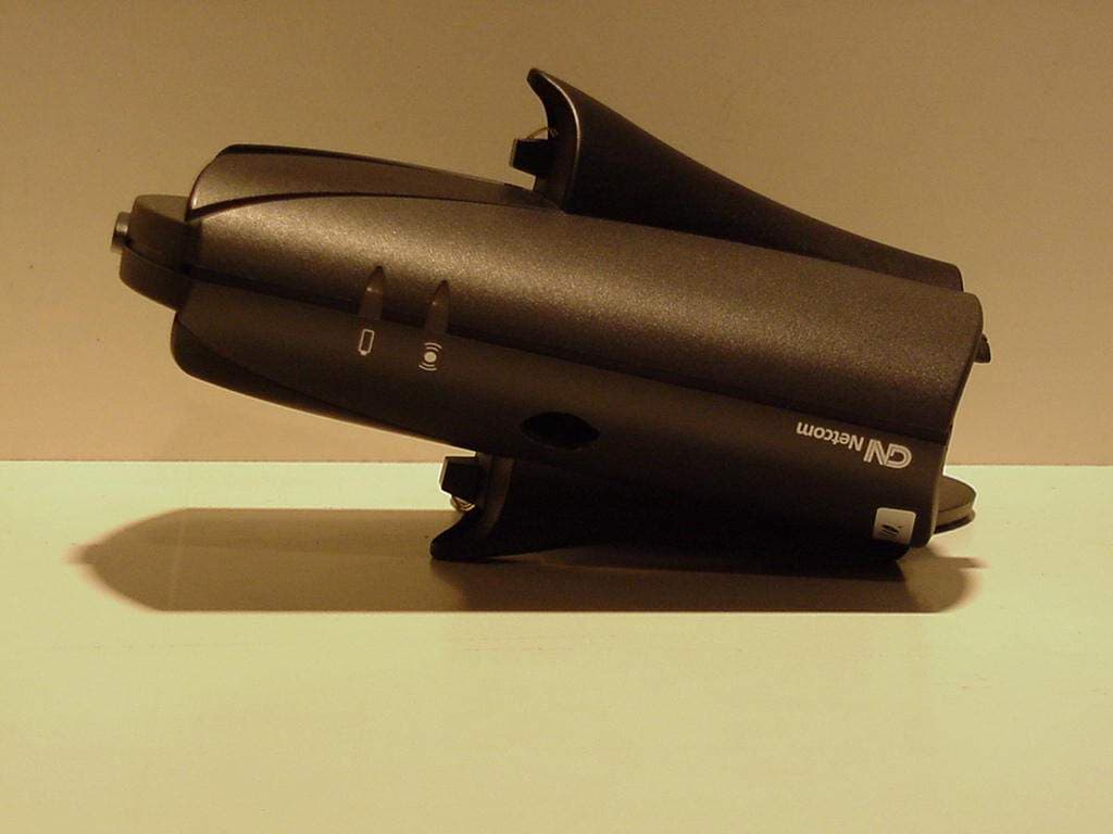
Click to zoom
Application Details
- Equipment Class
- DSS - Part 15 Spread Spectrum Transmitter
- Date of Grant
- Feb 28, 2001
- Application Purpose
- Original Equipment
- Date of Application
- Nov 01, 2000
- Equipment Note
- Headset
- Frequency Range
- 2402.00000000 - 2480.00000000
- Company
- GN Audio A/S
- Country
- Denmark
Documents & Files
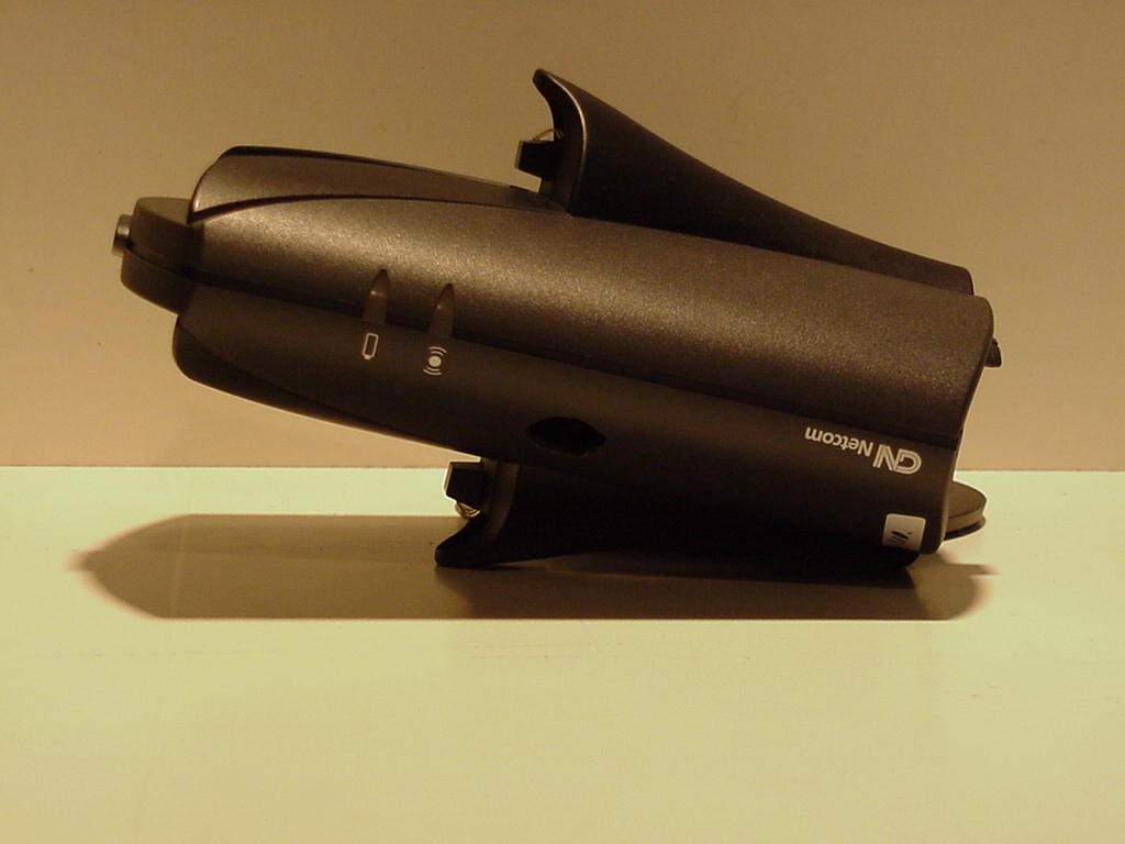
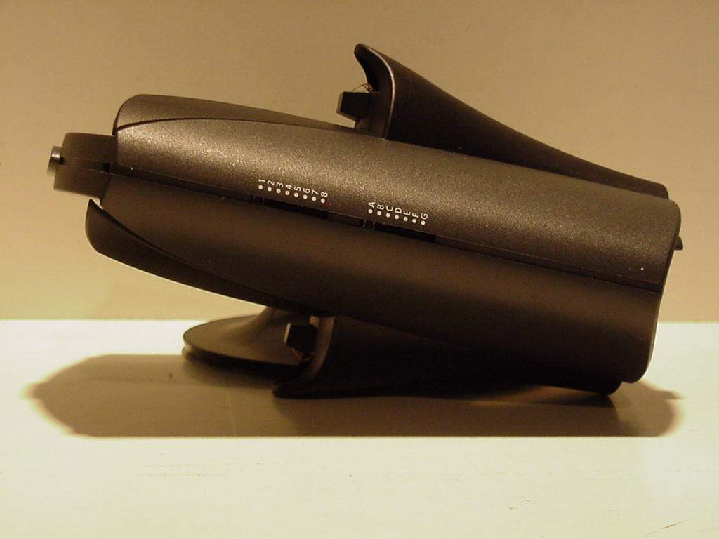
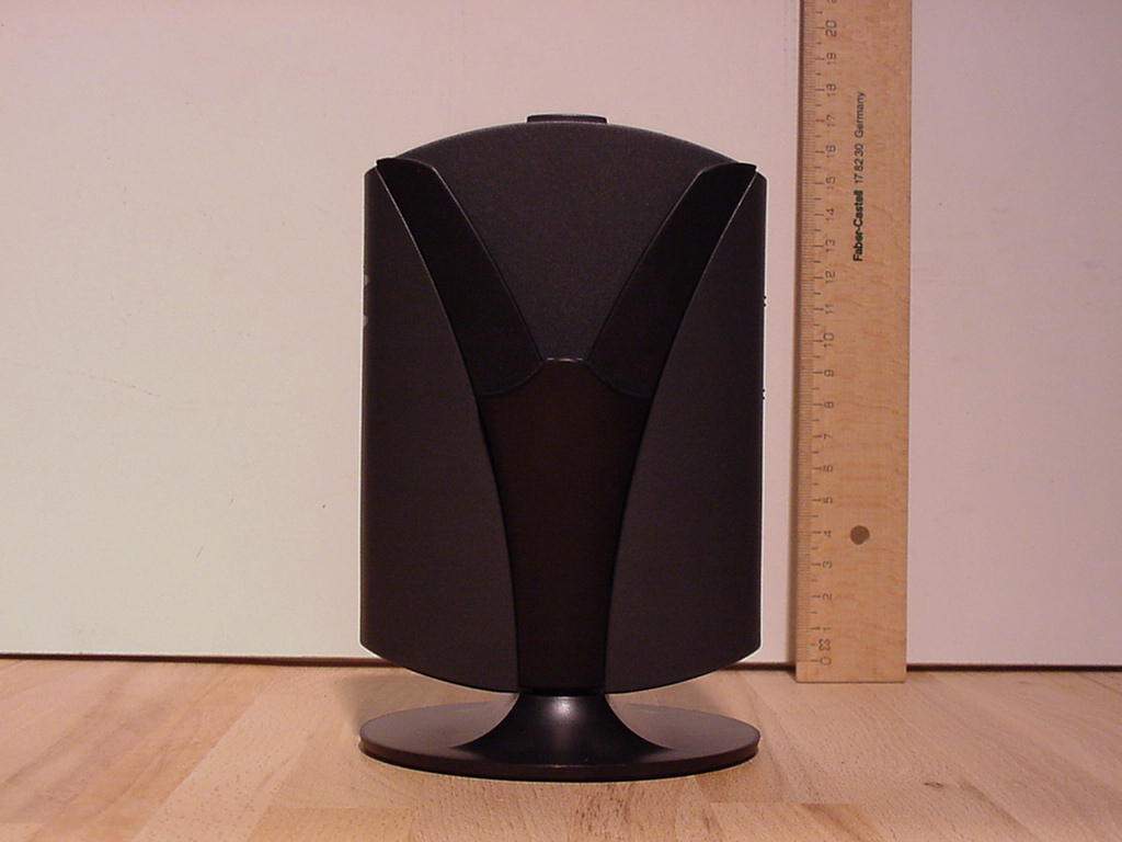

Document Text
Text extracted from the exhibit documents filed with the FCC. Open a document above to read the original.
Users Manual
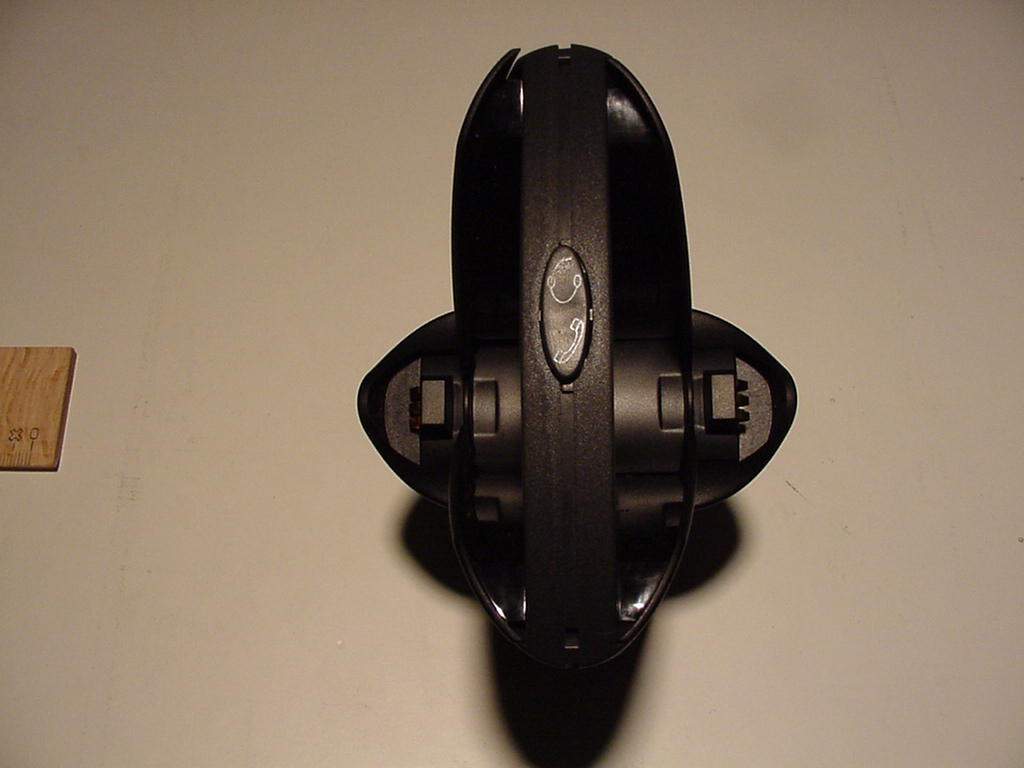
GN 9010 Assembling GN 9010 1. A. Disconnect handset cord from telephone and connect it to socket marked <Handset> at the bottom of base unit (A). B. Connect cord with modular plugs (D) to handset socket of the telephone and to socket marked <Telephone> at the bottom of the base unit. (If your telephone has a headset socket, just connect cord with modular plugs (D) to the headset socket at the telephone and to the socket marked <Telephone> at the bottom of the base unit. Then refer to step 1.C. ) C. Connect power unit adaptor (C) to socket marked <powersymbol> at the bottom of base unit, and then to a power socket. D. Switch on power. 2. Mount base unit on stand (B) by turning clockwise until secure. The three cords can extend from the front or back of the base unit as you wish. 3. Insert headset into base unit. Both sides of base unit can be used. The battery charging indicator (V) on base unit will light up. This side will be referred to as the front of the base unit. Before setting up GN 9010 to your telephone 4. The battery in the headset is not charged when delivered. To start, place headset in base unit for at least 45 min. before making the adjustments below. It takes 1½ hours to fully charge the battery of an GN 9010. Note: If your telephone has volume control, set the volume in the middle position. Checking the system 5. Remove headset from the base unit. The link will be instantly established and the on-line indicator (IV) on front of the base unit will light up. If the on-line indicator does not light up, place headset in base unit and remove it again to reset the headset. 0-10 seconds after having removed the headset from the base unit, the on-line indicator (IIX) on the headset starts flashing. If the on-line indicator on the headset does not flash, press simultaniously on both the upper and lower part of the volume button for 5 sec. The system is now working. Make sure that the mute function is off. If the mute function is on, you will hear a beep every 3 seconds in your headset. (see Technical Data) Turn off the mute function by pressing the mute button (VI) on the headset once. Setting up GN 9010 to your telephone Adjusting GN 9010 to your telephone 6. Put on your headset. 7. Lift handset from telephone (or if available on your terminal press the headset button) and listen for a dial tone in your headset. 8. If there is no dial tone, adjust the telephone termination switch (III) at the rear of base unit. Move from A to G until the dial tone is clear. If the dial tone is just as clear in position A as in G, leave switch in position A. Adjusting the microphone volume 9. Change from headset to handset position by pressing the headset/handset button on top of base unit once. 10. Put on your headset, call someone using your handset and ask the person to help you evaluate the volume of your voice. 11. Adjust the microphone volume control (II) from 1 to 8 by first talking in the handset and then in the headset in each position. When the person hears no difference whether you talk in the handset or headset, you have the correct setting. If the best setting is 7 or 8, it may be necessary to move the telephone termination switch (A-G) to G. Adjusting the headset for your comfort 12. You can wear the headset on your right or left ear, whichever side you prefer. To switch side, simply rotate the boom arm (H). The boom arm click-stops when it cannot turn any further. Warning: Do not force the boom arm over the top of the headset. 13. Adjust the length of the headband (F) so the headset rests comfortably on your head. The T-bar support (E) should be placed just above your free ear. 14. Adjust the boom arm so the microphone (I) is positioned approximately 2 cm from your mouth. Using GN 9010 Answering and making phone calls with GN 9010 15. Put on your headset. 16. Set the headset/handset button on top of base unit in headset position (see fig. 5). 17. Pick up handset (or if available on your terminal press the headset button). 18. Answer or make a call. 19. You can now move freely up to 10 meters away from the base unit, depending on the environment in your office building. If you move out of transmission range, GN 9010 lets you know by means of a beep every 10 seconds in your headset.(see Technical Data) 20. To end call, put down handset. Functions on the headset Adjusting the volume 21. To increase or reduce volume in your headset, press successively on the upper (+) or lower (-) part of the oval volume control (VII) on the headset. When the volume reaches maximum or minimum, you will hear a beep in your headset. (see Technical Data) Muting the microphone 22. To talk without your caller hearing you, press the mute button (VI) on the headset. You are still able to hear your caller. When the microphone is muted, you will hear a beep every 3 seconds in your headset. (see Technical Data) Powersave 23. When GN 9010 is out of range, you will hear a beep every 10 sec. When returning into range again, the headset will link up automaticly. The headset can be turned off by pressing simultaniously on the upper and the lower part of volume buttom. You will hear a long deep tone. You can turn the headset on again by pressing upper and lower part of volume buttom, and you will hear a shot beep. Charging the battery 24. When GN 9010 is not in use, place the headset in the base unit. Ensure that the on-line indicator is switched off. If the on-line indicator is still on, press the headset/handset button.This ensures optimum battery lifetime. When placed in the base unit, the battery charging indicator (V) automatically lights up and the headset is charged. It takes 1½ hours to fully charge the battery of an GN 9010. A fully charged battery provides 2 hours of talktime. If battery power gets too low, GN 9010 lets you know by sending a beep every 20 seconds in your headset. (see Technical Data) Pairring/Bonding 25. To make the headset work, it must be pairred with the base unit. The base unit and the he…
Text truncated - open the document above for the full version.
Users Manual
GN9020-D Digital Wireless System GN9010-BT Bluetooth™ Wireless System User Guide 12345678 ABCDEFG Components 1. Base Station A. Headset/Handset Selector B. Microphone Volume Control C. Telephone Compatibility Setting D. Battery Charging Indicator E. Headset Mode Indicator (base) 2. Stand 3. Telephone Cord 4. AC Power Adapter 5. Receiver Housing F. Ear Cushion Mounted on Earplate G. Mute Button H. Receive Volume Control Button I. Headset Mode Indicator (headset) 6. Adjustable Headband 7. Stabilizer 8. Flexible Microphone Boom 9. Microphone 10. Foam Cover for Microphone 6. 2. 5. 4. 3. C. 10. 7. 1. 9. 8. A. B. D.E. F. H. I. G. Charge battery for 3 hours prior to use. Assembling1 Connect all cords. 2 Attach the base station to the stand. Charging the Battery 3 Insert the headsetinto the base station(either side can be used). The battery chargingindicator on thebase illuminates. 4 The headset batteryis not charged when delivered.Place the headset in the base for 3hours before makingthe followingadjustments. It takes3 hours to fullycharge the battery.When fully charged,the battery chargingindicator flashes. — A fully charged GN9020-D provides 7 hoursof talktime.— A fully charge GN9010-BT provides 2 hoursof talktime. Netcom Netcom Act-AssemblyFirst draft 7-11-00 Second draft 8-23-00 Checking the System5 If your telephone has volume control, set the volume in the middle position. 6 Press the headset/handset selector to switch on the headset. The headset modeindicator on the base stationilluminates. 7 The headsetmode indicatoron the headsetbegins flashingwithin 10 seconds. If theheadset modeindicator doesnot flash, recheckassembly. 8 The system is now working. 9 If the lights are still off, the headset/handset selectoris in handset position. Press the headset/handsetselector once. Adjusting to your Telephone10 Put on the headset. 11 Make sure the mutefunction is off. Ifyou hear a beepevery 3 seconds, themute function is on.Turn off the mutefunction by pressingthe mute buttononce. 12 Lift the handsetfrom your telephoneand listen for a dialtone in your headset. 13 If there is no dialtone, adjust the tele-phone compatibilitysetting until the dialtone is clear. If dialtone is clear for bothA and G, set to A. ¥1¥2¥3¥4¥5¥6¥7¥8¥A¥B¥C¥D¥E¥F¥G Adjusting the Microphone Volume14 Put on the headset. 15 Press the headset/handset selectorto switch to handset mode. 16 Call someone using your handset and ask the personto help you evaluate the volume of your voice. 17 Using theheadset/handset selectorto toggle back and forthbetween handset andheadset mode, adjustthe microphone volumecontrol from 1 to 8 byfirst talking in thehandset and then in theheadset in each switch position. Position 1 isthe lowest volume settingand position 8 is thehighest volume setting. 18 When the person hearsno difference whetheryou talk in the handsetor headset, you have thecorrect setting. If the setting is 7 or 8, it maybe necessary to move thetelephone compatibilitysetting to G. Somephone handsets mayalways be louder than the headset. ¥1¥2¥3¥4¥5¥6¥7¥8¥A¥B¥C¥D¥E¥F¥G Answering and Placing Calls19 Put on the headset. 20 Set the headset/handset selectorto headset position. 21 Lift the handsetfrom the phone.Answer or placethe call. 22 You can now movefreely away from the base station. Ifyou move out oftransmission range,you will hear a beepin the headset every10 seconds. 23 To end the call,replace the handseton the phone. Netcom Adjusting the Receive Volume24 To increase or decrease thevolume, press the upper (+)or lower (-) part of the oval volume control on the headset. When the volume reaches maximum or minimum, you will hear a beep in your headset. Muting the Microphone25 To talk without the otherparty hearing you, pressthe mute button on theheadset. When themicrophone is muted,you will hear a beepevery 3 seconds. Whenthe mute function is on,you can still hear theother party. Recharging the Battery26 To ensure optimumbattery life, when notin use, place the headsetin the base station withthe headset/handsetselector in the handsetposition. The batterycharging indicator illuminates duringrecharging. It takes 3hours to fully chargethe battery. When fullycharged, the indicatorflashes. If battery power gets too low, you will hear a beep in your headset every20 seconds. Comfort Adjustments28 You can wear theheadset on yourright or left ear,whichever side youprefer. To switchsides, simply rotatethe microphoneboom below theheadband. NOTE:Do not force theboom over the topof the headset. 29 Adjust the length ofthe headband so theheadset rests com-fortably on yourhead. The stabilizershould be placed justabove your free ear.Adjust the flexiblemicrophone boom sothe microphone ispositioned approxi-mately 1/2” (12 mm)from your mouth. 30 To change or cleanthe leatherette earcushion, firstremove the earplateby turning theearplate 45 degreescounter-clockwise.Once removed, theear cushion can betaken off theearplate.To use the optionalfoam ear cushion,first remove theearplate andleatherette cushion.Then place thefoam cushion onthe earplate. 31 Gently remove themicrophone foam coverto clean or change. Frequently Asked QuestionsWhy can’t I hear a dial tone?• Check that all cords are connected correctly. • Be sure the AC power adapter is plugged in and power is turned on. • Be sure the headset/handset selector is in headset position and the headset mode indicators are illuminated. • Be sure the battery is fully charged.• Be sure the serial numbers on the base station and headset match. The numbers must match for operation. • Adjust the telephone compatibility setting.Why doesn’t the other person hear me?• Be sure the mute function is off.• Re-adjust the microphone volume.• Check the position of the microphone making sure that it is placed at the corner of your mouth. • You may be out of range. Move closer to the base station. Why do I hear a beep in my headset?• A beep every 20 seconds means the battery is getting low and needs to be charged. For proper char…
Text truncated - open the document above for the full version.
Attestation Statements
Registergericht h registered in:Vorstand h Board of Directors:7 layers AG, Borsigstrasse 11 Ratingen, HRB 3264Dr. Wolfgang Dahm40880 Ratingen, Germany AufsichtsratsvorsitzendehDr. Hans-Jürgen MeckelburgPhone: +49 (0) 2102 749 0 Chairman of the Supervisory Board:Fax: +49 (0) 2102 749 350 Dr. Sabine Grobeckerwww.7Layers.com 03.11.2000 Phone +49 (0) 2102 749 306 Fax +49 (0) 2102 749 350 application for GN Netcom, FCC-ID: PB7GN9000 Dear Sirs, The system GN 9000 Bluetooth (FCC ID: PB7GN9000) consists of two components, the GN 9010 Headset and the Base unit. Both components are radio transmitters. Both compents have been tested seperately according to the FCC rules. Uploaded documents related to the base unit are named with base_xxxxx.yyy, documents related to the headset are named with headset_xxxxx.yyy, and documents related to both are named with both_xxxxxx.yyy The grant should be issued for the whole system, because both components are marketed under the same name, GN 9000 Bluetooth. Thank you very much With kind regards Torsten Lohoff 7layers AG Federal Communications Commission (FCC) Projektname: 3_DIGI_GN9000_01
Attestation Statements
Registergerichth registered in:Vorstandh Board of Directors:7 layers AG, Borsigstrasse 11 Ratingen HRB 3264Dr. Wolfgang Dahm40880 Ratingen, Germany AufsichtsratsvorsitzendehDr. Hans-Jürgen MeckelburgPhone: +49 (0) 2102 749 0 Chairman of the Supervisory Board:Fax: +49 (0) 2102 749 350 Dr. Sabine Grobeckerwww.7layers.com Annex Additional declaration part according FCC 15.247 for Bluetooth devices Version: 2000-01-11 (Annex - Additional declaration part according FCC 15.247 for Bluetooth devices) Page 2 of 5 pages 1 Output power and channel separation of a Bluetooth device in the different operating modes: The different operating modes (data-mode, acquisition-mode) of a Bluetooth device don’t influence the output power and the channel spacing. There is only one transmitter which is driven by identical input parameters concerning these two parameters. Only a different hopping sequence will be used. For this reason the check of these RF parameters in one op-mode is sufficient. 2 Frequency range of a Bluetooth device: Hereby we declare that the maximum frequency of this device is: 2402 – 2480 MHz. This is according the Bluetooth Core Specification V 1.0B (+ critical errata) for devices which will be operated in the USA. This was checked during the Bluetooth Qualification tests (Test Case: TRM/CA/04-E). Other frequency ranges ( e.g. for Spain, France, Japan) which are allowed according the Core Specification are not supported by this device. 3 Co-ordination of the hopping sequence in data mode to avoid simultaneous occupancy by multiple transmitters: Bluetooth units which want to communicate with other units must be organised in a structure called piconet. This piconet consist of max. 8 Bluetooth units. One unit is the master the other seven are the slaves. The master co-ordinates frequency occupation in this piconet for all units. As the master hop sequence is derived from it’s BD address which is unique for every Bluetooth device, additional masters intending to establish new piconets will always use different hop sequences. 4 Example of a hopping sequence in data mode: Example of a 79 hopping sequence in data mode: 40, 21, 44, 23, 42, 53, 46, 55, 48, 33, 52, 35, 50, 65, 54, 67, 56, 37, 60, 39, 58, 69, 62, 71, 64, 25, 68, 27, 66, 57, 70, 59, 72, 29, 76, 31, 74, 61, 78, 63, 01, 41, 05, 43, 03, 73, 07, 75, 09, 45, 13, 47, 11, 77, 15, 00, 64, 49, 66, 53, 68, 02, 70, 06, 01, 51, 03, 55, 05, 04 (Annex - Additional declaration part according FCC 15.247 for Bluetooth devices) Page 3 of 5 pages 5 Equally average use of frequencies in data mode and behaviour for short transmissions: The generation of the hopping sequence in connection mode depends essentially on two input values: 1. LAP/UAP of the master of the connection 2. Internal master clock The LAP (lower address part) are the 24 LSB’s of the 48 BD_ADDRESS. The BD_ADDRESS is an unambiguous number of every Bluetooth unit. The UAP (upper address part) are the 24 MSB’s of the 48 BD_ADDRESS. The internal clock of a Bluetooth unit is derived from a free running clock which is never adjusted and is never turned off. For synchronisation with other units only offset are used. It has no relation to the time of the day. Its resolution is at least half the RX/TX slot length of 312.5 μs. The clock has a cycle of about one day (23h30). In most case it is implemented as 28 bit counter. For the deriving of the hopping sequence the entire LAP (24 bits), 4 LSB’s (4 bits) (Input 1) and the 27 MSB’s of the clock (Input 2) are used. With this input values different mathematical procedures (permutations, additions, XOR- operations) are performed to generate the sequence. This will be done at the beginning of every new transmission. Regarding short transmissions the Bluetooth system has the following behaviour: The first connection between the two devices is established, a hopping sequence was generated. For transmitting the wanted data the complete hopping sequence was not used. The connection ended. The second connection will be established. A new hopping sequence is generated. Due to the fact that the Bluetooth clock has a different value, because the period between the two transmission is longer (and it cannot be shorter) than the minimum resolution of the clock (312.5 μs). The hopping sequence will always differ from the first one. 6 Receiver input bandwidth and behaviour for repeated single or multiple packets: The input bandwidth of the receiver is 1 MHz. In every connection one Bluetooth device is the master and the other one is the slave. The master determines the hopping sequence (see chapter 5). The slave follows this sequence. Both devices shift between RX and TX time slot according to the clock of the master. Additionally the type of connection (e.g. single or multislot packet) is set up at the beginning of the connection. The master adapts its hopping frequency and its TX/RX timing according to the packet type of the connection. Also the slave of the connection will use these settings. Repeating of a packet has no influence on the hopping sequence. The hopping sequence generated by the master of the connection will be followed in any case. That means, a repeated packet will not be send on the same frequency, it is send on the next frequency of the hopping sequence. (Annex - Additional declaration part according FCC 15.247 for Bluetooth devices) Page 4 of 5 pages 7 Dwell time in data mode The dwell time of 0.3797s within a 30 second period in data mode is independent from the packet type (packet length). The calculation for a 30 second period is a follows: Dwell time = time slot length * hop rate / number of hopping channels *30s Example for a DH1 packet (with a maximum length of one time slot) Dwell time = 625 μs * 1600 1/s / 79 * 30s = 0.3797s (in a 30s period) For multislot packet the hopping is reduced according to the length of the packet. Example for a DH5 packet (with a maximum length of five time slots) Dwell time = 5 * 625 μs * 1600 * 1/5 *1/s /…
Text truncated - open the document above for the full version.
Attestation Statements
Note : The following test results relate only to the devices specified in this document. This report shall not be reproduced in parts without the written approval of the testing laboratory Answer Applicant: Digianswer A/S Skalhuse 5 DK-9240 Nibe Test Laboratory: 7 layers AG Borsigstrasse. 11 D-40880 Ratingen Germany Telephone: +49 (0) 2102 749 100 Fax: +49 (0) 2102749 111 Registergericht h registered in:Vorstand h Board of Directors:7 layers AG, Borsigstrasse 11 Ratingen, HRB 3264Dr. Wolfgang Dahm40880 Ratingen, Germany AufsichtsratsvorsitzendehDr. Hans-Jürgen MeckelburgPhone: +49 (0) 2102 749 0 Chairman of the Supervisory Board:Fax: +49 (0) 2102 749 350 Dr. Sabine Grobeckerwww.7Layers.com -----Ursprüngliche Nachricht----- Von: OET [mailto:[email protected]] Gesendet am: Freitag, 29. Dezember 2000 19:57 An: [email protected] Betreff: To: Torsten Lohoff, null From: Joe Dichoso [email protected] FCC Application Processing Branch Re: FCC ID PB7GN9015 Applicant: GN Netcom A/S Correspondence Reference Number: 17585 731 Confirmation Number: EA99204 1) The FCC identifier has been changed to what you requested. However, the new label has an FCC logo that is only for DOC approved devices. Please explain/correct. 7layers: The label layout by GN Netcom was not correct. It has been changed because it is not an DOC approval. An updated layout is enclosed. 2) Verify that the frequency range from the center frequency of the lowest channel to the center frequency of the highest channel is 2402-2480 MHz. 7layers: See separate document Annex "Additional declaration part according FCC 15.247 for BT devices" section 2. 3) The requested conducted Output power is 2.08 mW. While the test data shows only -1.9 dBm(.645 mW). Please explain/correct accordingly. 7layers: Due to the fact that the conducted output power (max. on 2402 MHz is -1.9 dBm (0.645 mW), see test report 4_DIGI_0100_BT_FCCd) will be authorized in the grant, please change the output power in the application to 0.645 mW. Provide the following with regard to the device operating in the data mode(FHSS) 4) a) The transmitter cannot coordinate its hopping sequence with the hopping sequence of other transmitters, or vice versa, for the purpose of avoiding the simultaneous occupancy of individual hopping frequencies by multiple transmitters. Provide a description on how the device complies with this rule. 7layers: See separate document Annex "Additional declaration part according FCC 15.247 for BT devices" section 3. 5) b) The system shall hop to channel frequencies that are selected at the system hopping rate from a pseudorandomly ordered list of hopping frequencies. Indicate how the pseudorandom hopping sequence is derived. Provide a list of channel frequencies and a sample of a few sequences. 7layers: See separate document Annex "Additional declaration part according FCC 15.247 for BT devices" section 4. 6) c) Each frequency must be used equally on the average by each transmitter. Except for voice systems, each new transmission may not start at the same point in the sequence or the frequencies will not be used equally used. Therefore, Describe where the next transmission starts when all frequencies are not used for a previous message. This is required because some transmissions may need only a few frequency hops to be completed. i.e. If the transmission started on the same frequency each time, this frequency would be used more than the others if many short transmissions were sent. 7layers: See separate document Annex "Additional declaration part according FCC 15.247 for BT devices" section 5. 7) d) Section 15.247(a)1 indicates that the system receivers shall have input bandwidths that match the hopping channel bandwidths of their corresponding transmitters and shall shift frequencies in synchronization with the transmitted signals. Please explain how the device complies with this rule when a packet is repeated or when multiple packets are sent. What is the receiver input bandwidth? How does the receiver shift frequencies and determine which frequency to shift to in order to synchronize with this transmitter? 7layers: See separate document Annex "Additional declaration part according FCC 15.247 for BT devices" section 6. 9) e) Compliance with the dwell time requirement. Provide the following information with regard to the device operating in the page and inquiry mode under the Spread spectrum Hybrid requirements in Section 15.247(f) and Section 15.247(a)1. 7layers: See separate document Annex "Additional declaration part according FCC 15.247 for BT devices" section 7. 9) f) Compliance with the minimal channel separation. 7layers: See separate document Annex "Additional declaration part according FCC 15.247 for BT devices" section 8. 10) g) 20 dB bandwidth plot. 1MAX Ref Lvl 21.3 dBm Ref Lvl 21.3 dBm RF Att 30 dB 1.3 dB Offset 1.3 dB Offset A UnitdBm Center2.441 GHzSpan3 MHz300 kHz/ RBW 10 kHz VBW 30 kHz IN1 1MA SWT 76 ms 1MA -70 -60 -50 -40 -30 -20 -10 0 10 20 1 1 2 Delta 2 [T1] -20.06 dB -263.52705411 kHz 1 [T1] -5.74 dBm 2.44098998 GHz 2 [T1] -20.06 dB -263.52705411 kHz 1 [T1] -22.18 dB 133.26653307 kHz Date: 9.SEP.2000 20:25:02 Plot of 20 dB bandwidth in inquiry mode = 600 kHz. The markers on the screen are not set correctly so the bandwidth of about 600 kHz is manually read from the screenshot. A UnitdBm 1.3 dB Offset 1.3 dB Offset RF Att 40 dB SWT 76 ms Ref Lvl 21.3 dBm Ref Lvl 21.3 dBm 1MAX1MA Center2.442 GHzSpan3 MHz300 kHz/ RBW 10 kHz VBW 30 kHz 1MA IN1 -70 -60 -50 -40 -30 -20 -10 0 10 20 1 1 2 Marker 1 [T1] -7.83 dBm 2.44200301 GHz 1 [T1] -7.83 dBm 2.44200301 GHz 1 [T1] -21.89 dB -306.61322645 kHz 2 [T1] -20.67 dB 234.46893788 kHz Date: 9.SEP.2000 20:55:32 Plot of 20 dB bandwidth in paging mode = 640 kHz. The markers on the screen are not set correctly so the bandwidth of about 640 kHz is manually read from the screenshot. 11) h) pseudorandom sequence examples and explanation of its derivation. 7layers: See separate document An…
Text truncated - open the document above for the full version.
Operational Description
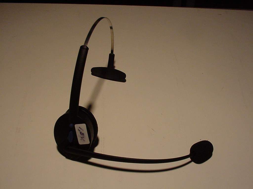
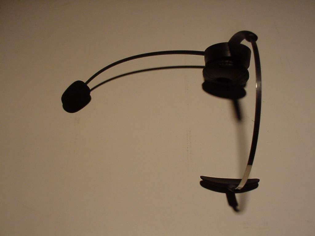
The headset is built with Digianswer Bluetooth technology; Baseband, embedded protocol stack and 0 dBm radio. The Bluetooth trademarks are owned by Telefonaktiebolaget LM Ericsson, Sweden Bluetooth TM Headset The GN 9000 Bluetooth TM headset is a ground-breaking new headset that goes one step beyond hands-free and enables communication without any cords. The headset can communicate with any other Bluetooth TM -enabled product, such as desktop telephones, mobile phones, and PCs. However, due to the cutting edge technology, not many of such products are Bluetooth TM -enabled today. For this reason, GN Netcom have developed a base unit that will allow the GN 9000 Bluetooth TM headset to communicate with standard telephones and telephone systems. The GN 9000 Bluetooth TM headset features a lightweight, elegant design and comes with the following functionalities: • Flexible boom arm which makes it easy to position the microphone correctly • Noise cancelling microphone which eliminates distracting background noise significantly • Fully adjustable headband with T-bar support for a perfect fit • Built-in mute button allows the user to speak freely without the caller hearing what is being said • Built-in volume control allows the user to adjust the incoming sound level • On-line indicator flashes when the link with the base unit has been established The GN 9000 Bluetooth TM combines the headset of today with the technology of tomorrow. The result is a superior wireless headset. Specifications Transmit Total harmonic distortion input at 1Pa...................<2% Frequency range...............................240-3400Hz ±3dB Receive Total harmonic distortion........................................<2% Frequency range...............................240-3400Hz ±3dB Max. sound pressure..................................<116dB SPL DC Power source...............................Re-chargeable battery Supply voltage..........................................................1.2V Battery type...........................................................NiMH Charge option........................................external charger Controls Volume control Mute Switch On/OFF Link LED RF Range............................................................Up to 10 m. Frequency band..................................................2.4 GHz Bluetooth Radio Compliant with the Bluetooth TM specification version 1.0B. Transmit power........................................0dBm (1mW) Receiver sensitivity.........................................< -80dBm Frequency range..................................2.402-2.480GHz (except France and Spain)
Test Report
EMC Measurement/Technical Report 4_DIGI_0100_BT_FCCe on 7 Layers AG Borsigstr. 11 40880 Ratingen Germany Note: The following test results relate only to the devices specified in this document. This report shall not be reproduced in parts without the written approval of the testing laboratory. Digianswer Bluetooth Base Unit DGABTBU100 Registergericht - registered in: Ratingen, HRB 3264 Aufsichtratsvorsitzende - Chairman of the Supervisory Board: Dr. Sabine Grobecker Vorstand - Board of Directors: Dr. Wolfgang Dahm Dr. Hans-Jürgen Meckelburg 7 layers AG, Borsigstrasse 11 40880 Ratingen, Germany Phone: +49 (0) 2102 749 0 Fax: +49 (0) 2102 749 350 http://www.7Layers.com Report Reference: Table of Contents 0. Summary 0.1 Technical Report Summary 0.2 Measurement Summary 1. Administrative Data 1.1 Testing Laboratory 1.2 Project Data 1.3 Applicant Data 1.4 Manufacturer Data 3. Testobject Data 3.1 General EUT Description 3.2 EUT Main Components 3.3 Ancillary Equipment 3.4 EUT Setups 3.5 Operating Modes 4. Measurement Results 4.1 Conducted Emissions 4.2 Occupied Bandwidth 4.3 Output Power 4.4 Spurious Emissions Conducted 5. Testequipment 6. Foto Report 7. Setup Drawings 8. Annex 3 3 4 6 6 6 6 6 8 8 9 9 9 9 11 11 13 15 18 32 34 36 39 Measurement plots 4.5 Spurious Emissions Radiated20 2. Product Labeling 2.1 FCC ID Label 2.2 Location of Label on the EUT 7 7 7 4.6 Dwell Time 4.7 Power Density 4.8 Channel Separation 4.9 Processing Gain 26 28 30 31 Page 2 of 60 Testreport Reference: 4_DIGI_0100_BT_FCCe 0 Summary 0.1 Technical Report Summary Type of Authorization Certification for an Intentional Radiator (Frequency Hopping Spread Spectrum) Applicable FCC Rules: Prepared in accordance with the requirements of FCC Rules and Regulations as listed in 47 CFR Ch.1 Parts 0 to 19 (10-1-98 Edition). The following subparts are applicable to the results in this test report. Part 2, Subpart J - Equipment Authorization Procedures, Certification Sections Part 15, Subpart C - Intentional Radiators § 15.201 Equipment authorization requirement § 15.203 Antenna requirements § 15.207 Conducted limits § 15.209 Radiated emission limits; general requirements § 15.247 Operation within the bands 902-928 MHz, 2400-2483,5 MHZ and 5…
Text truncated - open the document above for the full version.
Contact Information
Applicant
Steen Kaiser(Mr.)
Technical Contact
Non-Technical Contact
Digianswer A/STom Ringtved
[email protected]+45 96 71 00 25
Test Firm
7layers AGRobert Machulec
Technical Specifications
| # | Rule Parts | Frequency Range | Power Output | Tolerance |
|---|---|---|---|---|
| 1 | 15C | 2.40 GHz - 2.48 GHz | 645.00 µW | Hz |
Other Applications from GN Audio A/S
PB7-OTE13
Jan 28, 2013Bluetooth Headset Jabra OTE13
Equipment Class
DSS - Part 15 Spread Spectrum Transmitter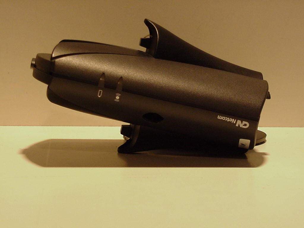
PB7GN9010
Mar 13, 2001GN 9000 Bluetooth base unit
Equipment Class
DSS - Part 15 Spread Spectrum Transmitter