PBPM-45C1-01Hand Held Radio
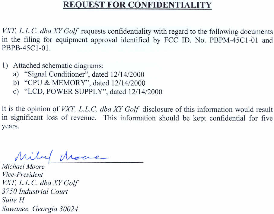
VXT, L.L.C.
Click to zoom
Application Details
- Equipment Class
- TNB - Licensed Non-Broadcast Station Transmitter
- Date of Grant
- Mar 05, 2002
- Application Purpose
- Original Equipment
- Date of Application
- Feb 25, 2001
- Equipment Note
- Hand Held Radio
- Frequency Range
- 450.00000000 - 480.00000000
- Company
- VXT, L.L.C.
- Country
- United States
Documents & Files
Document Text
Text extracted from the exhibit documents filed with the FCC. Open a document above to read the original.
Users Manual
X-45C1-01-30 Rev 1 User Guide for Model M-45C1-01 Handheld Golf GPS Unit And Model B-45C1-01 Base/Repeater Unit M-45C1-01 B-45C1-01 X-45C1-01-30 Rev 1 1 I. Introduction This guide covers operation of XY Golf’s Handheld Golf GPS unit and Base/Repeater Unit. The operation of either unit is very similar. Specific functionality of the units is defined by software, which utilizes a standard soft-key menu system to access various parameters and functions. NOTE: "THIS EQUIPMENT COMPLIES WITH PART 90 OF THE FCC RULES. ANY CHANGES OR MODIFICATIONS NOT EXPRESSLY APPROVED BY THE MANUFACTURER COULD VOID THE USER'S AUTHORITY TO OPERATE THE EQUIPMENT." II. Usage The M-45C-01, Hand Held Unit (HHU) is designed to be used by a golfer. It relies on GPS and predefined data to provided assistance to the golfer in the form of distance data, shot advice, and other information. During usage the unit ordinarily resides in a cradle attached to a golf cart or golf bag. The golfer will typically pick up hold the unit and refer to it before making each shot and then place it back in the cradle. The B-45C-01, Base/Repeater Unit (BSU), is designed to operate as a fixed unit in either of two modes. In Base Mode, it serves as the communication controller for all HHUs and Repeaters within a specific area (typically a single golf course). It also provides Differential GPS (DGPS) correction data to HHUs to enhance their positional accuracy. In Repeater Mode, the B-45C-01 is used to extend the radio coverage of the BSU. This may be needed if the size of a particular installation is unusually large, or there are obstacles like hills or large buildings blocking radio coverage to specific areas. A typical Base/Repeater installation utilizes an outdoor fix-mounted antenna no higher than 30 feet above ground level. Appropriate FCC Licensing or Authorization is required prior to station operation. III. Operation This section describes the operation of the units. Since the many options are enabled or disabled via a separate database, the actual menu options available may be slightly different than those shown here. This document will show all options that are currently available. X-45C1-01-30 Rev 1 2 A. Main Menu When the unit is initially powered up or reset the main menu will appear as shown in Figure 1. The actual screen may appear differently than the one shown here, or may not appear at all, depending on options set in the unit initialization database. Figure 1. Main Menu 1) Play Course 2) Settings 3) System Menu 4) FCC Menu X-45C1-01-30 Rev 1 3 I. FCC Menu The FCC Menu contains all of the controls required for Part 15 and Part 90 FCC testing. This screen is only accessible in special in-house firmware builds and is not available to the end user. The FCC Menu is shown below. Figure 9. FCC Menu Five Modes are available here: Receive, CW, Continuous Data, Radio Off, and Normal Operation. Additionally, the operator may set the frequency of the radio to one of three points: The lower and upper band limits of the radio, and the center of the band. A mode may be activated by highlighting it using the Down/Up soft-keys, then pressing the Enter soft key. The mode may be deactivated by pressing the Enter soft key again. NOTE: A status line near the bottom of the display will show the current mode of operation. 1) Radio Receive Activating this function will place the Transceiver in Receive mode at the currently selected frequency. X-45C1-01-30 Rev 1 4 2) Radio CW Activating this mode will cause the transceiver to key-up. No data will be applied to modulate the signal. This function will time out after approximately 3 minutes to protect the transceiver. The unit will revert to Receive Mode after the time-out. CAUTION: The transceiver is designed to operate at a maximum 50% Transmit/Receive duty cycle. Overheating and equipment failure may occur if the Radio CW mode is repeatedly activated. 3) Transmit Data Activating the Transmit Data mode will cause the unit to continuously transmit an ASCII data pattern. This function will time out after approximately 3 minutes to protect the transceiver. The unit will revert to Receive Mode after the time-out. CAUTION: The transceiver is designed to operate at a maximum 50% Transmit/Receive duty cycle. Overheating and equipment failure may occur if the Transmit Data mode is repeatedly activated. 4) Radio Off This mode will shut off the power supplies to both the Transmitter and Receiver sections of the transceiver. 5) Normal Operation Normal Operation Mode will cause the unit to behave as it normally does during operation. This involves transmitting an approximately 90-byte message at regular intervals, then reverting back to receive. The message intervals are as follows: Model Application Typical Message Interval M-45C1-01 Handheld Golfer Unit twice per minute B-45C1-01 Base/Repeater Unit once per second X-45C1-01-30 Rev 1 5 6) Set Frequency This feature allows the user to set the transceiver frequency to any of three points. The unit will initially be set to the center of the radio band (Mid Freq.) upon power-up. The current frequency will be displayed on a status line near the bottom of the display whenever this item is selected. Pressing the Enter soft key causes the frequency to switch to the next frequency. The Set Frequency function may be used while the unit is in any of the above modes (Receive, Transmit, Normal, etc.). J. Radio Menu The Radio Menu contains all of the software-adjustable parameters related to the data radio and radio communication. This screen is only accessible in special in- house firmware builds and is not available to the end user. The Radio Menu is shown in Figure 10 below. Figure 10. Radio Menu 1) Adjust Pot This adjustment controls the DC bias that is applied to receive data signal (from the transceiver) before it enters the threshold detector. Typical adjustment procedures involve injecting a very low-level, modulated signal into the receiver and adjusting this cont…
Text truncated - open the document above for the full version.
Operational Description
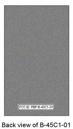
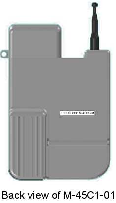
20 December 2000 Equipment Setup A. Handheld Golf GPS Unit 1. Charging The units internal battery may be charged in several ways depending on what equipment is available. The recommended charge method is to place the unit in the custom wall-mounted or desktop charging cradle. The unit will sense that it is in a charging cradle and automatically turn off and switch to the proper mode. Alternatively, the unit may be charged via an external battery charger. The unit’s MUST be set turned OFF prior to connection with an external charger, and left OFF while charging. The ON/OFF switch is located on the back of the unit next to the charging connector. Once connected, the charger will fully charge the battery and then shut off. NOTE: The unit’s battery operates at 7.2 volts nominal. The actual voltage may be considerably higher for a short time after a full charge. This will temporarily cause the transceiver output power to be greater than the typical operating power of 2 watts. However, in actual use, this situation is atypical and short lived. 2. Operation The ON/OFF switch is located on the back of the unit next to the charging connector. The unit may be operated as usual immediately after power-up. B. Base/Repeater Unit 1. Charging The Base/Repeater unit does not contain in internal battery and therefore does not need to be charged. 2. Operation In normal operation, the Base/Repeater unit should be connected to the custom 7.2 volt supply. If one is unavailable, a suitable substitute may be made with a power supply capable of providing regulated 7.2 volts at 1.5 Amps. 20 December 2000 FCC Identifier locations As required per 2.926 The following illustrations show the planned location and size of the FCC Identifier Label on each unit.
Parts List/Tune Up Info
DM-3473 Synthesized UHF Data Module Technical Manual Part Number: 242-3473-XXX DM-3473 Synthesized UHF Data Module 001-3473-202 Revision 1 February 2000 Copyright 2000 by Dataradio COR Ltd. Dataradio COR Ltd. designs and manufactures radios and radio modems to serve a wide variety of data communication needs. The Dataradio Corporation produces equipment for the fixed data market including SCADA systems for utilities, petrochemical, waste and fresh water management markets and RF boards for OEM applications in the Radio Frequency Data Capture market. PRODUCT WARRANTY The manufacturer's warranty statement for this product is available from Dataradio COR Ltd., 299 Johnson Avenue, Box 1733, Waseca, MN 56093-0833. Phone (507) 835-8819. The information in this document is subject to change without notice. is a trademark of Dataradio Inc. 1 TABLE OF CONTENTS 1GENERAL INFORMATION 1.1SCOPE OF MANUAL. . . . . . . . . . . . . . . . . . . . . . . . . . . . . . . . . . . . . . . . . . . . . . . . . . . . . . . . . . . . . . . . . . . . . . . . .1-1 1.2EQUIPMENT DESCRIPTION . . . . . . . . . . . . . . . . . . . . . . . . . . . . . . . . . . . . . . . . . . . . . . . . . . . . . . . . . . . . . . . . . .1-1 GENERAL. . . . . . . . . . . . . . . . . . . . . . . . . . . . . . . . . . . . . . . . . . . . . . . . . . . . . . . . . . . . . . . . . . . . . . . . . . 1-1 DM-3473 SYNTHESIZER PROGRAMMING . . . . . . . . . . . . . . . . . . . . . . . . . . . . . . . . . . . . . . . . . . . . . . . 1-1 1.3TRANSCEIVER IDENTIFICATION . . . . . . . . . . . . . . . . . . . . . . . . . . . . . . . . . . . . . . . . . . . . . . . . . . . . . . . . . . . . .1-1 1.4PART NUMBER BREAKDOWN. . . . . . . . . . . . . . . . . . . . . . . . . . . . . . . . . . . . . . . . . . . . . . . . . . . . . . . . . . . . . . . .1-2 1.5CUSTOMER SERVICE/TECHNICAL SUPPORT . . . . . . . . . . . . . . . . . . . . . . . . . . . . . . . . . . . . . . . . . . . . . . . . .1-2 1.6PRODUCT WARRANTY . . . . . . . . . . . . . . . . . . . . . . . . . . . . . . . . . . . . . . . . . . . . . . . . . . . . . . . . . . . . . . . . . . . . . .1-3 1.7REPLACEMENT PARTS. . . . . . . . . . . . . . . . . . . . . . . . . . . . . . . . . . . . . . . . . . . . . . . . . . . . . . . . . . . . . . . . . . . . . .1-3 1.8IF A PROBLEM ARISES . . . . . . . . . . . . . . . . . . . . . . . . . . . . . . . . . . . . . . . . . . . . . . . . . . . . . . . . . . . . . . 1-3 FACTORY REPAIR. . . . . . . . . . . . . . . . . . . . . . . . . . . . . . . . . . . . . . . . . . . . . . . . . . . . . . . . . . . . . . . . . . . . . . . . . . .1-3 GENERAL SPECIFICATIONS . . . . . . . . . . . . . . . . . . . . . . . . . . . . . . . . . . . . . . . . . . . . . . . . . . . . . . . . . . . . . . . . .1-4 2INSTALLATION 2.1PRE-INSTALLATION CHECKS. . . . . . . . . . . . . . . . . . . . . . . . . . . . . . . . . . . . . . . . . . . . . . . . . . . . . . . . . . . . . . . .2-1 2.2INTERFACING WITH DATA EQUIPMENT . . . . . . . . . . . . . . . . . . . . . . . . . . . . . . . . . . . . . . . . . . . . . . . . . . . . . .2-1 CONNECTOR PIN ASSIGNMENTS . . . . . . . . . . . . . . . . . . . . . . . . . . . . . . . . . . . . . . . . . . . . . . . . . . . . . . . . . . . .2-1 3PROGRAMMING 3.1INTRODUCTION. . . . . . . . . . . . . . . . . . . . . . . . . . . . . . . . . . . . . . . . . . . . . . . . . . . . . . . . . . . . . . . . . . . . . . . . . . . . .3-1 3.2DM-3473 SERIAL INTERFACE SPECIFICATION . . . . . . . . . . . . . . . . . . . . . . . . . . . . . . . . . . . . . . . . . . . . . . . .3-1 3.3FRACTIONAL-N SYNTHESIZER. . . . . . . . . . . . . . . . . . . . . . . . . . . . . . . . . . . . . . . . . . . . . . . . . . . . . . . . 3-1 INTRODUCTION. . . . . . . . . . . . . . . . . . . . . . . . . . . . . . . . . . . . . . . . . . . . . . . . . . . . . . . . . . . . . . . . . . . . . 3-1 SYNTHESIZER DATA PROTOCOL. . . . . . . . . . . . . . . . . . . . . . . . . . . . . . . . . . . . . . . . . . . . . . . . . . . . . . 3-2 SYNTHESIZER DATA . . . . . . . . . . . . . . . . . . . . . . . . . . . . . . . . . . . . . . . . . . . . . . . . . . . . . . . . . . . . . . . . 3-2 3.4SYNTHESIZER BIT DEFINITIONS . . . . . . . . . . . . . . . . . . . . . . . . . . . . . . . . . . . . . . . . . . . . . . . . . . . . . . 3-3 INTRODUCTION. . . . . . . . . . . . . . . . . . . . . . . . . . . . . . . . . . . . . . . . . . . . . . . . . . . . . . . . . . . . . . . . . . . . . 3-3 D-WORD. . . . . . . . . . . . . . . . . . . . . . . . . . . . . . . . . . . . . . . . . . . . . . . . . . . . . . . . . . . . . . . . . . . . . . . . . . . 3-3 C-WORD. . . . . . . . . . . . . . . . . . . . . . . . . . . . . . . . . . . . . . . . . . . . . . . . . . . . . . . . . . . . . . . . . . . . . . . . . . . 3-4 B-WORD. . . . . . . . . . . . . . . . . . . . . . . . . . . . . . . . . . . . . . . . . . . . . . . . . . . . . . . . . . . . . . . . . . . . . . . . . . . 3-4 A0-WORD. . . . . . . . . . . . . . . . . . . . . . . . . . . . . . . . . . . . . . . . . . . . . . . . . . . . . . . . . . . . . . . . . . . . . . . . . . 3-4 3.5SYNTHESIZER LOAD PARAMETER EXAMPLE . . . . . . . . . . . . . . . . . . . . . . . . . . . . . . . . . . . . . . . . . . . 3.4 3.6RECOMMENDED SYNTHESIZER LOAD SEQUENCE. . . . . . . . . . . . . . . . . . . . . . . . . . . . . . . . . . . . . . . . . . .3-11 RECEIVE TO TRANSMIT SEQUENCE. . . . . . . . . . . . . . . . . . . . . . . . . . . . . . . . . . . . . . . . . . . . . . . . . . . . . . . . .3-11 TRANSMIT TO RECEIVE SEQUENCE. . . . . . . . . . . . . . . . . . . . . . . . . . . . . . . . . . . . . . . . . . . . . . . . . . . . . . . . .3-12 3.7A0 WORD ALGORITHM . . . . . . . . . . . . . . . . . . . . . . . . . . . . . . . . . . . . . . . . . . . . . . . . . . . . . . . . . . . . . . . . . . . . .3-13 4CIRCUIT DESCRIPTION 4.1GENERAL. . . . . . . . . . . . . . . . . . . . . . . . . . . . . . . . . . . . . . . . . . . . . . . . . . . . . . . . . . . . . . . . . . . . . . . . . . . . . . . . . . .4-1 INTRODUCTION. . . . . . .…
Text truncated - open the document above for the full version.
Test Report
KTL Test Report:0L0437RUS1 Applicant:VXT, L.L.C. 3750 Industrial Court Suite H Suwanee, GA 30024 Equipment Under Test:PM-45C1-01 Handheld Radio (E.U.T.) FCC ID:PBPM-45C1-01 In Accordance With:FCC Part 90, Subpart I Private Land Mobile Transmitter Tested By:KTL Dallas Inc. 802 N. Kealy Lewisville, TX 75057-3136 Authorized By: Tom Tidwell, EMC/Wireless Group Manager Date:1/27/01 Total Number of Pages:34 KTL Dallas FCC PART 90, SUBPART I PRIVATE LAND MOBILE TRANSMITTER EQUIPMENT: M-45C1-01 Handheld Radio PROJECT NO.: 0L0437RUS1 Page 2 of 34 Table of Contents Section 1. Summary of Test Results........................................................................................3 Section 2. General Equipment Specification.............................................................................5 Section 3. RF Power Output....................................................................................................7 Section 4. Modulation Characteristics......................................................................................8 Section 5. Occupied Bandwidth.............................................................................................10 Section 6. Spurious Emissions at Antenna Terminals.............................................................12 Section 7. Field Strength of Spurious Emissions....................................................................15 Section 8. Frequency Stability...............................................................................................18 Section 9. Transient Frequency Behavior...............................................................................20 Section 10. Test Equipment List..............................................................................................23 Annex A - Test Methodologies..................................................................................................24 Annex B - Test Diagrams..........................................................................................................30 KTL Dallas FCC PART 90, SUBPART I PRIVATE LAND MOBILE TRANSMITTER EQUIPMENT: M-45C1-01 Handheld Radio PROJECT NO.: 0L0437RUS1 Page 3 of 34 Section 1.Summary of Test Results Manufacturer:XY Golf Model No.:M-45C1-01 Serial No.:S02 General:All measurements are traceable to national standards. These tests were conducted on a sample of the equipment for the purpose of demonstrating compliance with FCC Part 90, Subpart I. New SubmissionProduction Unit Class II Permissive ChangePre-Production Unit THIS TEST REPORT RELATES ONLY TO THE ITEM(S) TESTED. THE FOLLOWING DEVIATIONS FROM, ADDITIONS TO, OR EXCLUSIONS FROM THE TEST SPECIFICATIONS HAVE BEEN MADE. See “ Summary of Test Data”. NVLAP LAB CODE: 100426-0 KTL Dallas Inc. authorizes the above named company to reproduce this report provided it is reproduced in its entirety and for use by the company’s employees only. Any use which a third party makes of this report, or any reliance on or decisions to be made based on it, are the responsibility of such third parties. KTL Dallas Inc. accepts no responsibility for damages, if any, suffered by any third party as a result of decisions made or actions based on this report. This report applies only to the items tested. KTL Dallas FCC PART 90, SUBPART I PRIVATE LAND MOBILE TRANSMITTER EQUIPMENT: M-45C1-01 Handheld Radio PROJECT NO.: 0L0437RUS1 Page 4 of 34 Summary Of Test Data NAME OF TESTPARA. NO.SPEC.MEAS.RESULT RF Power Output90.205100 W1.5 WComplies Audio Frequency Response TIA EIA- 603.3.2.6 N/AN/AN/A Audio Low-Pass Filter Response TIA EIA- 603.3.2.6 N/AN/AN/A Modulation Limiting TIA EIA- 603.3.2.6 +/-0.19 kHzComplies Occupied Bandwidth90.210Mask DMask DComplies Spurious Emissions at Antenna Terminals 90.21050+10Log(P) -66.07 dB (-34.4 dBm) Complies Field Strength of Spurious Emissions 90.21050+10Log(P)-24.5 dBm erpComplies Frequency Stability90.2135 ppm0.4 ppmComplies Transient Frequency Behavior 90.214 Footnotes: 1. This transmitter does not have a provision for voice modulation. . KTL Dallas FCC PART 90, SUBPART I PRIVATE LAND MOBILE TRANSMITTER EQUIPMENT: M-45C1-01 Handheld Radio PROJECT NO.: 0L0437RUS1 Page 5 of 34 Section 2.General Equipment Specification Transmitter Supply Voltage Input: 3.6 Vdc battery Frequency Range: 450 - 480 MHz Necessary Bandwidth: 12 kHz Type(s) of Modulation: F3E (Voice) F1DF2DD7W (QAM) Other Data Rate(s) 4800, 9600 bps Internal/External Data Source: Internal Emission Designator: 20K0 Output Impedance: 50 ohms RF Power Output (rated): 2 W Duty Cycle: Two transmissions per minute Channel Spacing(s): 12.5 kHz Operator Selection of Operating Frequency: Set in software Power Output Adjustment Capability: Not adjustable by user KTL Dallas FCC PART 90, SUBPART I PRIVATE LAND MOBILE TRANSMITTER EQUIPMENT: M-45C1-01 Handheld Radio PROJECT NO.: 0L0437RUS1 Page 6 of 34 System Description The EUT is a handheld data radio that is used on a golf course to communicate with a base unit (Model B-45C1-01). This system allows course data to be transmitted to the golfer. The handheld unit includes a GPS receiver to coordinate the location of the golfer. This information is transmitted back to the base unit. These radios operate in the 450 - 480 MHz band on 12.5 kHz channels. System Diagram Base Transmitter EUT KTL Dallas FCC PART 90, SUBPART I PRIVATE LAND MOBILE TRANSMITTER EQUIPMENT: M-45C1-01 Handheld Radio PROJECT NO.: 0L0437RUS1 Page 7 of 34 Section 3.RF Power Output NAME OF TEST: RF Power OutputPARA. NO.: 2.985 TESTED BY: D. LightTom Tidwell & Debbie JensenDATE: 1/4/01 Measurement Results:Complies. Measurement Data: Frequency (MHz) Measured Power (dBm) Rated Power (dBm) Measured/Rated (dB) 45033330 46533330 48033330 Measurement Conditions: Temperature:22 °C Humidity:50% Measurement Uncertainty:+/- 0.62 dB KTL Dallas FCC PART 90, SUBPART I PRIVATE LAND MOBILE TRANSMITTER EQUIPMENT: M-45C1-01 Handheld Radio PROJECT NO.: 0L0437RUS1 Page 8 of 34 Section 4.Modulation Char…
Text truncated - open the document above for the full version.
Contact Information
Applicant
Michael Moore(Vice-President)
Technical Contact
KTL Dallas, Inc.Alma Torres
[email protected]972-436-9600
802 N. Kealy · Lewisville, Texas · United States
Non-Technical Contact
KTL Dallas, Inc.Davida Hanson
[email protected]972-436-9600
Test Firm
Nemko Dallas, Inc.Michael Cantwell
Technical Specifications
| # | Rule Parts | Frequency Range | Power Output | Emission | Tolerance |
|---|---|---|---|---|---|
| 1 | 90.210 | 450 MHz - 480 MHz | 2 W | 11K0F2D | 0.5000000000 ppm |
Other Applications from VXT, L.L.C.

PBPB-45C1-01
Jun 03, 2001Base radio model B-45C1-01
Equipment Class
TNB - Licensed Non-Broadcast Station Transmitter