PBWA9R8900 MHz Cordless Telephone
Ascalade Technologies, Inc.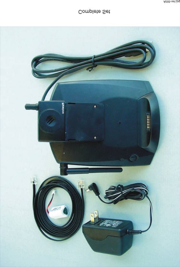
Click to zoom
Application Details
- Equipment Class
- DXX - Part 15 Low Power Communication Device Transmitter
- Date of Grant
- Oct 31, 2000
- Application Purpose
- Original Equipment
- Date of Application
- Oct 31, 2000
- Equipment Note
- 900 MHz Cordless Telephone
- Frequency Range
- 902.00000000 - 928.00000000
- Company
- Ascalade Technologies, Inc.
- Country
- Canada
Documents & Files
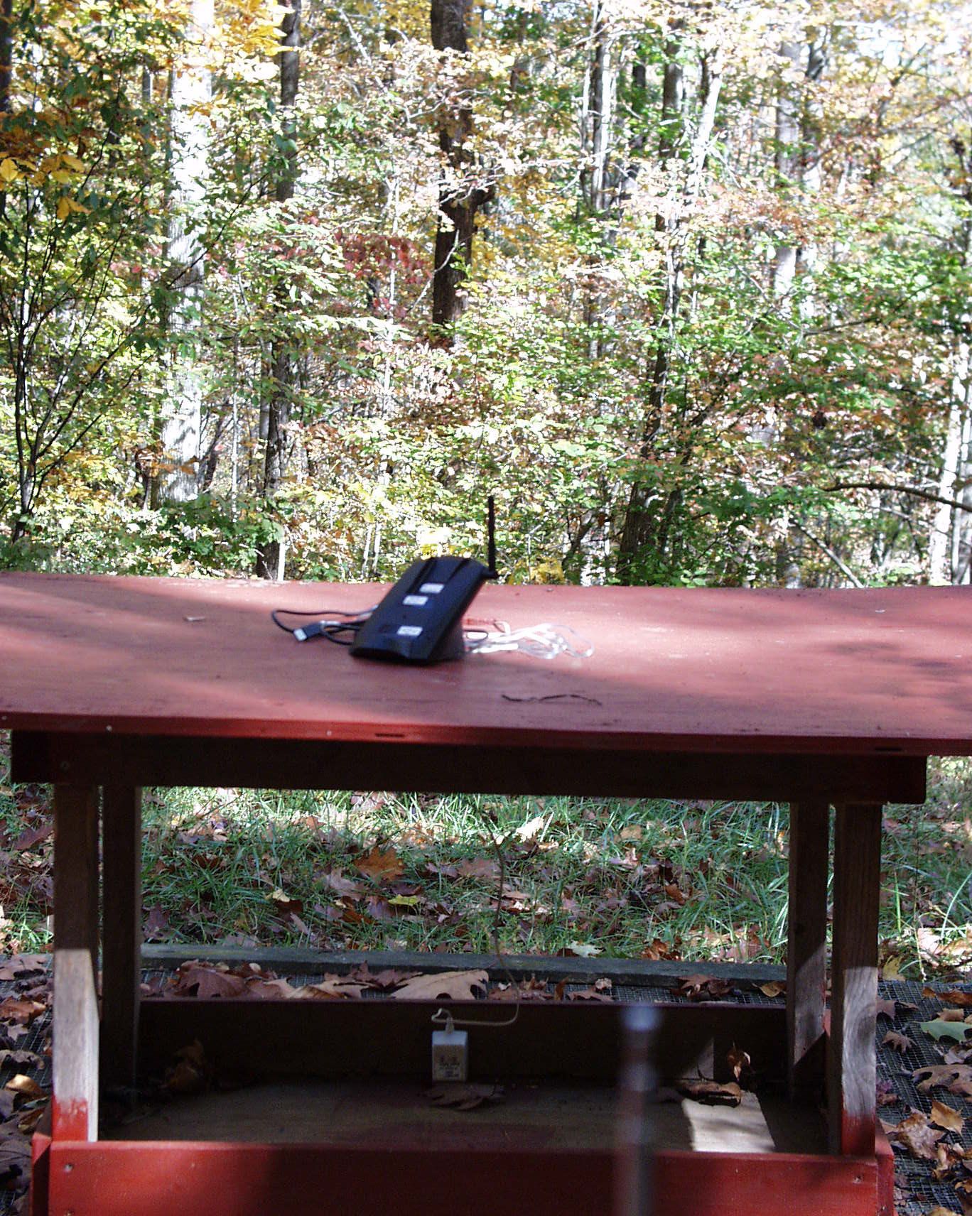
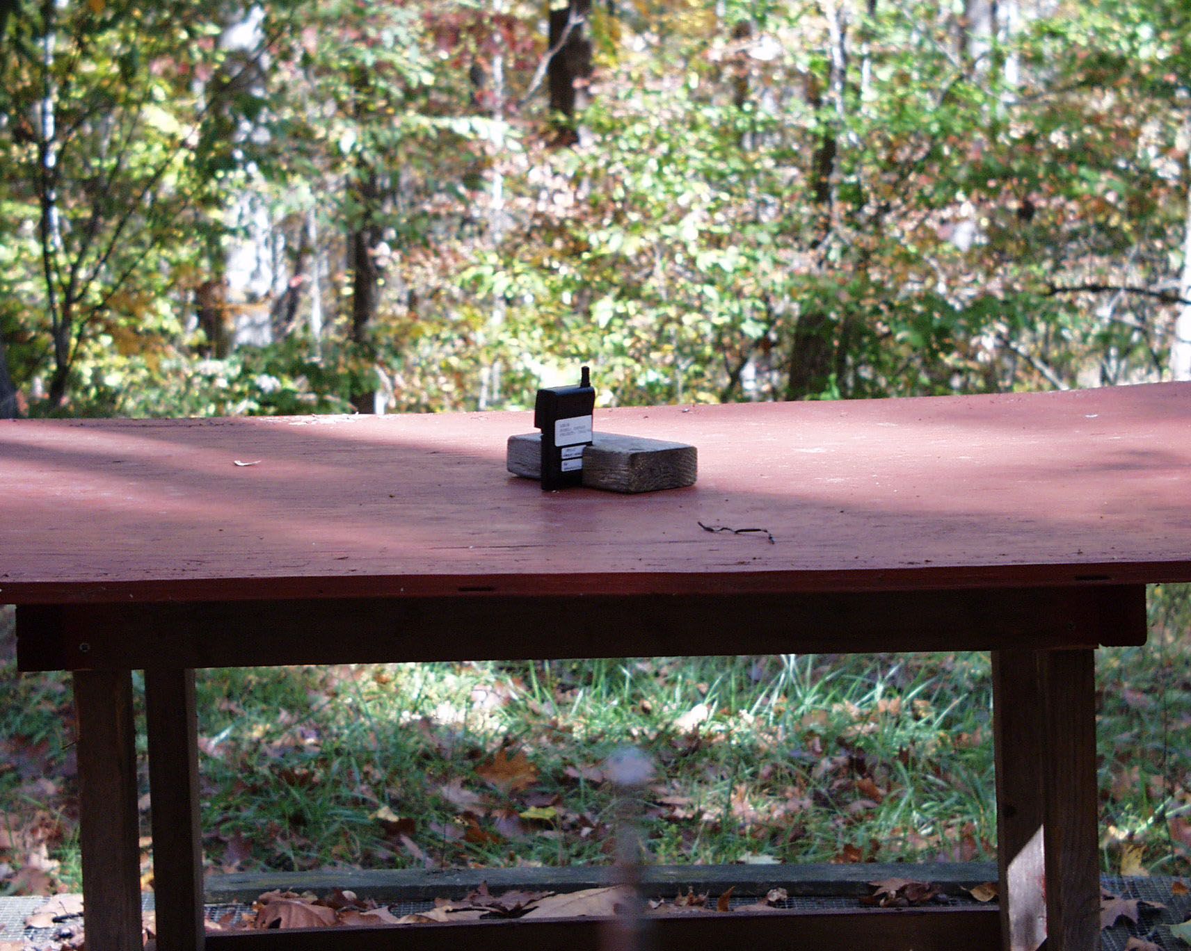
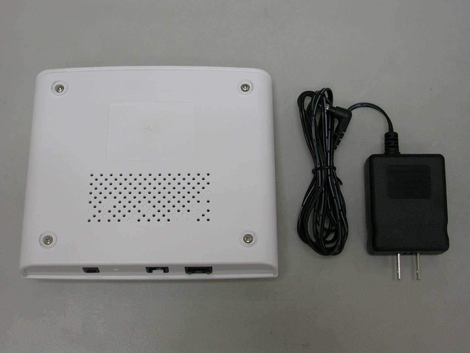
Document Text
Text extracted from the exhibit documents filed with the FCC. Open a document above to read the original.
Block Diagram
File Name:A005bs-bd.doc Base Baseband Block Diagram Page(s):1 of 1 This document contains confidential and proprietary information of ARKON Networks Inc. No part may be reproduced or used except as authorized by written permission. ANT SWITCH Q210 & LPF LN_IN HK_SW DTMF T901 Line Isolation Transformer SWITCH Q201 U501 CID DECODER & VMWI 3.579MHz RG_DE RING DETECT U901 HOT_SYNC U301-C RF MODULE LN_OUT U301-A U301-D DOCKING PCB (FOR PDA HOT_SYNC) REF_CLK RSSI RX_DT TX_DT VTX VRO DTMF_EC 8MHz TONE/PULSE SWITCH SW208 USB Cable TELEPHONE LINE INTERFACE Hookswitch U902 EXT. PHONE DETECT U301-B EX_DE PDA DOCKING CONNECTOR X201 DIAL/S PAGE/ SYNC KEY SW209 Q101 Charging Plate DL202 CHARGE / IN USE LED VOLTAGE REGULATOR U101 (6V) U102 (3V3) D102 VDM VDD6 (6V)VRO (3V3) D101 VDD CRADLE DETECTION Q102 INVERTER CR_DE CR_DT /CR_DT R801 JK801 DC POWER JACK ENABLE SDT SCLK MCU U201 USB Connector T R
Block Diagram
File Name: A005brf-bd.doc Base Unit 900MHz RF Module Block Diagram Page(s) : 1 of 2 This document contains confidential and proprietary information of ARKON Networks Inc. No part may be reproduced or used except as authorized by written permission. RF Signal Transmit Paths -8dBm -6dBm -17dBm TX PLL TX Buffer Compressor Mic Amp Mic Data Latch Control STB DATA REF_CLK CLK RX PLL RX Buffer RX VCO Mixer IF Amp1 Ceramic Filter F2 Ceramic Filter F1 IF Amp2 Data Comp QUAD Pre Amp Expander Soft Control RX Amp AF RSSI RSSI U1 Data Out IF Amp Q7 Amp Q5 Dielectric Filter F3 LNA Q3 Dielectric Filter F4 Duplexer Dielectric Filter F5 PA Q1 TX VCO Q4 Q2 Modulator TX_DATA U1 contain Dual PLL, IF Amps, RSSI, Data Comp, Quad, Pre Amp, Expander, Soft Control, RX Amp, Mic Amp, Compander. Q6 TX 902.3 - 904.2MHz -9dBm with probe -2dBm with 50 ohm loading 50mVp Note: * probe: SMA + 15pF cap 8MHz from BASEBAND Audio Signal Input File Name: A005brf-bd.doc Base Unit 900MHz RF Module Block Diagram Page(s) : 2 of 2 This document contains confidential and proprietary information of ARKON Networks Inc. No part may be reproduced or used except as authorized by written permission. RF Signal Receive Paths ν TX PLL TX Buffer Compressor Mic Amp Mic Data Latch Control STB DATA REF_CLK CLK RX PLL RX Buffer RX VCO Mixer IF Amp1 Ceramic Filter F2 Ceramic Filter F1 IF Amp2 Data Comp QUAD Pre Amp Expander Soft Control RX Amp AF RSSI RSSI U1 Data Out IF Amp Q7 Amp Q5 Dielectric Filter F3 LNA Q3 Dielectric Filter F4 Duplexer Dielectric Filter F5 PA Q1 TX VCO Q4 Q2 Modulator TX_DATA U1 contain Dual PLL, IF Amps, RSSI, Data Comp, Quad, Pre Amp, Expander, Soft Control, RX Amp, Mic Amp, Compander. Q6 -108 dBm 5 Vpp 500m Vp Audio LO 915.1 - 917.0MHz RX 925.8 - 927.7MHz 10.7MHz 8 MHz From BASEBAND Audio Signal Input
Block Diagram
File Name:A005hs-bd.doc Handset Baseband Block Diagram Page(s):1 of 1 This document contains confidential and proprietary information of ARKON Networks Inc. No part may be reproduced or used except as authorized by written permission. JK2 Headset jack MCU U1 Control Logic U4 (OR-Gate) DATA DATA RF MODULE MIC+ VISOR PDA DATA J1 Visor Interface Connector Flash RAM U11 ADDRESS DATA ANT DL1 IN USE LED BUZZER BZ1 DRIVER B_Tone Q9 Q13 Q11 DRIVER DRIVER E_OUT RX_DT MIC_IN TX_DT COMMAND DATA SWITCH Q8 ENABLE SDT SCLK SWITCH Q10 SWITCH Q4 VTX RX_Vcc VIF X2 4MHz EEPROM U3 (OPTIONAL) REF_CLK LB (Low Batt) NB801 Battery connector CR_DE EP1 VBB 3.6V Rechargeable Battery Pack Voltage Regulator U2, U5 Vcc Vcc1 FIFO U6, U7 /SCE1 /SWE /MWAKE EARPIECE CONTROL MIC- U9 CRADLE DETECT Q14 CHARGING PROTECTION DZ801 D801 Charging Plate
Block Diagram
File Name: A005hrf-bd.doc Handset 900MHz RF Module Block Diagram Page(s) : 1 of 2 This document contains confidential and proprietary information of ARKON Networks Inc. No part may be reproduced or used except as authorized by written permission. RF Signal Transmit Paths TX PLL TX Buffer Compressor Mic Amp Mic Data Latch Control STB DATA REF_CLK CLK RX PLL RX Buffer RX VCO Mixer IF Amp1 Ceramic Filter F2 Ceramic Filter F5 IF Amp2 Data Comp QUAD Pre Amp Expander Soft Control RX Amp AF RSSI RSSI U1 Data Out IF Amp Q7 Amp Q5 SAW Filter F3 LNA Q3 SAW Duplexer F4 PA Q1 TX VCO Q4 Q2 Modulator TX_DATA U1 contain Dual PLL, IF Amps, RSSI, Data Comp, Quad, Pre Amp, Expander, Soft Control, RX Amp, Mic Amp, Compander. Q6 TX 925.8 - 927.7 MHz -10dBm with probe -2.5dBm with 50 ohm loading -10dBm -16dBm Note: * probe: SMD + 1.5pF Cap Audio Signal Input 4 MHz From BASEBAND File Name: A005hrf-bd.doc Handset 900MHz RF Module Block Diagram Page(s) : 2 of 2 This document contains confidential and proprietary information of ARKON Networks Inc. No part may be reproduced or used except as authorized by written permission. RF Signal Receive Paths ν TX PLL TX Buffer Compressor Mic Amp Mic Data Latch Control STB DATA REF_CLK CLK RX PLL RX Buffer RX VCO Mixer IF Amp1 Ceramic Filter F2 Ceramic Filter F5 IF Amp2 Data Comp QUAD Pre Amp Expander Soft Control RX Amp AF RSSI RSSI U1 Data Out IF Amp Q7 Amp Q5 SAW Filter F3 LNA Q3 SAW Duplexer F4 PA Q1 TX VCO Q4 Q2 Modulator TX_DATA U1 contain Dual PLL, IF Amps, RSSI, Data Comp, Quad, Pre Amp, Expander, Soft Control, RX Amp, Mic Amp, Compander. Q6 500m Vp Audio 3.0 Vpp -108 dBm RX 902.3 - 904.2 MHz LO 913.0 - 914.9 MHz 10.7 MHz Audio Signal Input 4 MHz From BASEBAND
Block Diagram
File Name:A005-cp11.docFCC Part 15 / IC RSS-210 Application Report 900MHz Analog Cordless Phone Communication Protocol Page:1 of 4 This document contains confidential and proprietary information of ARKON Netw orks Inc. No part may be reproduced or used except as authorized by written permission. Initialization When the handset is on cradle or base power supply restored after interruption, the base unit sends the follow ing information through charging contacts: • Updated Security Code • Control channel data including transmission frequency The transmission frequency is determined after checking the last used channel to make sure it is vacant. This ensures that the handset has a clean channel to use. If the last used channel is occupied, the base unit will scan to find a vacant channel. The base unit will send the above information to the handset 9 times. Once the handset receives the channel-acquire command, it will update its security code and transmission frequency. Base Unit Handset Detection of Handset Charging 9 Data Packets Only Security Code + Control Channel Data (Wire System) After the “ACQ + Channel” command is received, the “Reply” command will be sent continuously for about 200 packets through wireless system of the new control channel. Security OK Command Security OK Command When “RESP” command is received, 9 consecutive commands of Security OK will then be sent out. After a channel is selected successfully, the “ACQ + Channel” command will be sent. File Name:A005-cp11.docFCC Part 15 / IC RSS-210 Application Report 900MHz Analog Cordless Phone Communication Protocol Page:2 of 4 This document contains confidential and proprietary information of ARKON Netw orks Inc. No part may be reproduced or used except as authorized by written permission. Calling From Base When PAGE button is pressed or incoming call is received from the Base Unit, an RF link will be initiated by the base to the handset. The base can page the handset by first sending the “Channel acquire command”. Upon receiving this command, the handset sends back the “Channel response command”. Then the base sends the “Paging command”. Finally, the handset responds by sending the “Paging response command”. HandsetBase Unit Calling ACQ + Channel If an empty channel is found, calling will be initiated through the control channel. If all the channels are occupied, it will choose a random channel. The “ACQ” command will be sent continuously for about 5 seconds. RESP + Channel After the “ACQ + Channel” command is received, the “Reply” command will be sent continuously for about 5 seconds. Paging Command Paging Response Command After “RESP” command is received, the “Paging” command will be sent continuously for about 5 seconds. Transmission of “RESP” command is stopped, and the state and channel will be changed to the corresponding status. After the “Paging” command is received, it will send out 5 command packets of Paging Response. File Name:A005-cp11.docFCC Part 15 / IC RSS-210 Application Report 900MHz Analog Cordless Phone Communication Protocol Page:3 of 4 This document contains confidential and proprietary information of ARKON Netw orks Inc. No part may be reproduced or used except as authorized by written permission. Calling from Handset When the user makes a phone call by pressing the TALK key, ‘Link up command” signal will be sent to the base. When the base receives the command, it responses by sending back the “Channel response command”. This defines the communciation channel. The handset then sends out the “Phone on command” to the base. The base will respond back the “Phone on response command” to the handset. Base UnitHandset Calling Link Request Command Channel Response Command Phone On Command Phone On Response Command When the Base unit receives the request command from the Handset, the Base unit will scan and choose the first empty channel. This channel information will continuously be sent out in “Channel Response” command for about 5 seconds. The “Request” command is sent for max. 5 seconds until the response command is received. After the “Channel Response” command is received, the “Phone On” command will be sent out continuously for about 5 seconds. When the “Phone On Response” command is received, it will stop to send “Phone On” command. On receipt of “Phone On” command, the Base unit will send a response to the Handset. File Name:A005-cp11.docFCC Part 15 / IC RSS-210 Application Report 900MHz Analog Cordless Phone Communication Protocol Page:4 of 4 This document contains confidential and proprietary information of ARKON Netw orks Inc. No part may be reproduced or used except as authorized by written permission. Channel Scanning There are totally 20 channels with frequency allocation shown in the Technical Description. Once the handset is on cradle or the base resumes power, the security code along with the channel number are sent to the handset. The base will scan a channel and detect if there is any carrier in that channel. If that channel has no carrier, that means the channel is “clean”. The handset can request the base to change to another clear channel. This is done by first sending a “Link up command” to the base. The base will search a clean channel and send the “Channel response command” to the handset. After receiving the “Channel response command”, the handset will then send the “Channel command” to the base. Upon receiving this command, the base acknowledges by sending the “Change channel response command” to the handset. 4 When the “Change Channel Resp” command is received, Handset will stop sending “Change Channel Resp” command. Handset Base will switch to the chosen channel and send the “Channel Response” command continuously for about 5 seconds. Receiving the “Change Channel” command, Base will change the transmit and receive to a new channel and send the “Change Channel Resp” command to Handset After checking out the empty channel, the Handset sends the “Link Request” command for max. 5 s…
Text truncated - open the document above for the full version.
ID Label/Location Info
QC PASSED 8300010183612345 DC9V TELLINE THISDEVICECOMPLIESWITHPART15OFTHEFCCRULES. OPERATIONISSUBJECTTOTHEFOLLOWINGTWOCONDITIONS: 1)THISDEVICEMAYNOTCAUSEHARMFULINTERFERENCE,AND 2)THISDEVICEMUSTACCEPTANYINTERFERENCERECEIVED, INCLUDINGINTERFERENCETHATMAYCAUSEUNDESIREDOPERATION. PRIVACYOFCOMMUNICATUINMAY NOTBEENSUREDWHEN USINGTHISPHONE. ModelPRF500CordlessPhone LISTEDXXXX ITE EXXXXXX ARKONNetworksInc. COMPLIESWITHPART68,FCCRULES FCCREG.NO.: CANADA: JACK(USOC):RJ11C/CA11A REN:0.6B DC:9V200mA IndustryCanadaLabel Serialnumberlabel Mold-imprint Mold-imprint Mold-imprint QCLabel Label PULSE TONE HAC FCCID:PBWA9R8 MADEINCHINA R PRF500BaseUnit(Rear) A005-bs-rear.pdf Source:A005-bs-rear.cdr
ID Label/Location Info
Lexanlabel BATTERYCAUTIONLABEL Silk-screening PRF500HandsetModule TOREDUCERISK OFFIRE,USEONLYNi-MH BATTERYARKONBR01 CAUTION FCCID:PBWA9R8 MADEINCHINA CANADA: byARKON A005-hs.pdf HAC TM Source:A005-hs.cdr
Operational Description
File Name:A005-to10.docFCC Part 15 / IC RSS-210 Application Report 900MHz Analog Cordless Phone Theory of Operation Page:1 of 7 This document contains confidential and proprietary information of ARKON Netw orks Inc. No part may be reproduced or used except as authorized by written permission. GENERAL CONCEPT The PRF500 telephone is a radio transceiver designed to make or receive a telephone call without connecting a wire between the handset and the base station unit. Physically, PRF500 is equipped with two separate parts. The first part is the base unit. The base unit houses 2 physically separated hardware systems, namely phone system and Personal Data Assistant (PDA) docking system. The phone system functions as the base unit of the cordless phone, communicating with the handset and interfacing with phone line. This system includes a wide band transceiver and a telephone line interface. The PDA docking system is for docking of the PDA and interfacing with PC via a cable. The second part of PRF500 is a piggy-back handset module plugged into the expansion slot of the PDA, sharing the LCD of the PDA for telephone functionality. This handset module consists of a wide band FM transceiver, earpiece and headset jack. Once plugged into the PDA, the handset module will utilize the PDA’s LCD touch screen dialpad and microphone to function as a cordless phone handset. The phone system of the base unit and the handset module are operating in full duplex mode on one of the 20 channels in 902-928 MHz band. Their linking can only be achieved by means of a matched security code to prevent unauthorized access to one’s telephone line. There are up to 16.8 million (24-bit) digital security codes set by the microprocessor software. The detailed explanation of the theory of cordless phone system operation is described in the following sections. File Name:A005-to10.docFCC Part 15 / IC RSS-210 Application Report 900MHz Analog Cordless Phone Theory of Operation Page:2 of 7 This document contains confidential and proprietary information of ARKON Netw orks Inc. No part may be reproduced or used except as authorized by written permission. 1.FUNCTIONAL DESCRIPTION OF BASE UNIT (See Section on BLOCK DIAGRAM) 1.1Microprocessor The 8-bit MCU U201 operates at 8 MHz resonator frequency and on 5V DC. The device provides digitally generated DTMF. Other I/O pins are used to activate hook switch and LED indication, to page the handset, to detect cradle signal, extension phone and incoming ring, to activate data transfer to PC through Hot Sync, and for various controls such as Rx data and Tx data. An external power- up reset is incorporated to prevent the MCU from hanging. Internal watchdog is utilized to minimize erratic software operation. 1.2CID DECODING The CID Decoder IC U501 with Visual Message Waiting Indicator supports both on-hook and off-hook CID. When U501 detects CID in an incoming ring during standby mode, it activates the FSK signal decoding section. The incoming FSK signal from Tip/Ring is converted into digital data. The data (1 byte) is buffered in the decoder, waiting to be latched out by the MCU until the next byte comes in. After processing the CID data, the CID Decoder sends the CID data through the Tx data path to the Handset. When there is a second incoming call and the phone is in talk mode, phone call alert message will appear on the PDA screen. 1.3Ring Detect The ring detect circuit detects the presence of an incoming ringing signal. When the ringing voltage exceeds 40 Vrms, a current will flow through the LED section of the optocoupler U901. The output transistor of the optocoupler will give logic signal to the MCU in accordance with the frequency and cadence of the incoming ring. 1.4Battery Charging The voltage supply for this charging unit is 9V DC from the AC power adaptor. A series resistor in the circuit limits the maximum charging current. File Name:A005-to10.docFCC Part 15 / IC RSS-210 Application Report 900MHz Analog Cordless Phone Theory of Operation Page:3 of 7 This document contains confidential and proprietary information of ARKON Netw orks Inc. No part may be reproduced or used except as authorized by written permission. 1.5 Cradle data When handset is on the base, on-cradle is detected by Q102. MCU will send out command data through an inverter Q101 to the charging contacts and hence to the handset. 1.6 Baseband Signal Processor 2.6.1 Transmit Audio The audio signal from the phone line interface is amplified by U301C before it is sent to RF module. 2.6.2 Receive Audio The demodulated audio from the RF module is amplified by U301A and U301D before it is sent to the phone line interface. 1.7Line Interface At the line interface, the transformer T901 and optocouplers U901/U902 provide isolation between the phone network and the Base. The transformer also acts as a 2-to-4-wire hybrid network for transmit, receive, and sidetone signals to and from the telephone line. For protection against surges, there are two major protective components. The first one is a fuse FU901 that will open when there is large in-rush current (250 mA or more). The second one is a 275Vrms varistor VS901 which will limit the maximum voltage induced across the telephone line. High voltage capacitors C904 and C905 with 2kV isolation capability are provided for CID detection circuitry. 1.8RF Module The RF modules of the base and handset share the same design except that the transmit and the receive frequencies are interchanged and different Duplexer types are used due to space constraint. Detailed description is in item 3. File Name:A005-to10.docFCC Part 15 / IC RSS-210 Application Report 900MHz Analog Cordless Phone Theory of Operation Page:4 of 7 This document contains confidential and proprietary information of ARKON Netw orks Inc. No part may be reproduced or used except as authorized by written permission. 2.FUNCTIONAL DESCRIPTION OF HANDSET UNIT (See Section on BLOCK DIAGRAM) 2.1Microprocessor The 8-bit MCU U1 o…
Text truncated - open the document above for the full version.
Test Report
ENGINEERING STATEMENT In Connection With ARKON NETWORKS, INC. Model No. PRF500 Cordless Telephone FCC ID: PBWA9R8 Hyak Laboratories, Inc. has been retained to perform radiated and conducted spurious measurements on the PRF500 cordless telephone in accordance with Section 15.249 of FCC rules. I am an Electronics Engineer, a principal in the firm of Hyak Laboratories, Inc., Springfield, Virginia. My education and experience are a matter of record with the Federal Commu- nications Commission, having submitted numerous applications for equipment authorization. All tests were made by me or under my supervision in accordance with the rules and regulations of the Federal Communications Commission. ______________________________ Rowland S. Johnson Dated: October 10, 2000 INTRODUCTION Procedures of ANSI 63.4 (1992) were used. The PRF500 is a 20-channel analog, frequency modulation, 900 MHz band system operating between 902.30 - 904.20 and 925.800 - 927.700 MHz. COMPLIANCE_WITH_SECTION_15.249_OF_PART_15 15.249(a,b) The field strength of the radiation emission was measured and found to comply with the limits established by 15.249(a) and 15.209. (See data of Tables 1 and 2.) 15.249(c) Emissions radiated outside of the specified frequency bands, except for harmonics, were attenuated by at least 50 dB below the level of the fundamental or to the general radiated emission limits in 15.209, (whichever is the lesser attenuation). See Figures 1a, 1b, 2a and 2b for low and high channels. Operating channels (total of 20, see Appendix 8) are limited within the 902 - 928 MHz band to: Hand: Channel 1 925.800 MHz, Channel 20 927.700 MHz. Base: Channel 1 902.300 MHz, Channel 20 904.200 MHz. 15.207(a) AC power line conducted radio frequency voltage did not exceed 250uV (+48 dBuV) from .45 to 30 MHz (see Figures 3 and 4). DATA Tables and Figures referenced above follow immediately after this page. Description of measurement procedures and test equipment used in the measurements follow the data pages. 2 TABLE 1a RADIATED SPURIOUS EMISSIONS Measured at 3 meters PART 15(B) PARA. 15.249 Frequency Frequency To Which of Meter Antenna Field 1 Tuned Emission Reading Factor Intensity FCC Limit dB to (MHz) (MHz) (dBm) (dB) uV/m @ 3m uV/m @ 3m Limit 925.800 925.820 -53.2 32.4 20417V 50000 - 7.8 925.800 1853.420 -83.2 27.5 367H 500 - 2.7 925.800 2780.160 -102.8 30.3 53H 500 -20 925.800 3706.880 -101.6* 32.9 82V 500 -16 925.800 4633.600 -102.0* 33.3 82V 500 -16 925.800 5560.320 -100.8* 35.0 115** 500 -13 925.800 6487.040 -101.6* 35.8 115** 500 -13 925.800 7413.760 -102.0* 37.4 132** 500 -12 925.800 8340.480 - 98.8* 38.1 207** 500 - 7.7 925.800 9258.200 - 98.8* 38.6 219** 500 - 7.2 Note 1: uV/m = Log -dBu/m 20 dBu = dBm + antenna factor + 107 *Measured at 1 meter, extrapolated to 3 meters. **Measuring system noise floor. RBW 100 kHz to 1 GHz; 1 MHz > 1 GHz. Reduced if CW signal. H,V: Worst-case test antenna polarization. HAND-HELD UNIT RADIATED SPURIOUS EMISSIONS FCC ID: PBWA9R8 TABLE 1a (CH 01) 3 TABLE 1b RADIATED SPURIOUS EMISSIONS Measured at 3 meters PART 15(B) PARA. 15.249 Frequency Frequency To Which of Meter Antenna Field 1 Tuned Emission Reading Factor Intensity FCC Limit dB to (MHz) (MHz) (dBm) (dB) uV/m @ 3m uV/m @ 3m Limit 927.700 927.740 -51.4 32.4 22387V 50000 - 7.0 927.700 1855.480 -84.8 27.5 305V 500 - 4.3 927.700 2783.220 -103.4 30.3 50V 500 -20 927.700 3710.960 -102.9* 32.9 71H 500 -17 927.700 4638.700 -101.9* 33.3 83V 500 -16 927.700 5566.440 -100.8* 35.0 115** 500 -13 927.700 6494.180 -101.6* 35.8 115** 500 -13 927.700 7421.920 -102.2* 37.4 129** 500 -12 927.700 8349.660 -98.8* 38.1 207** 500 - 7.7 927.700 9277.390 -98.8* 38.6 219** 500 - 7.2 Note 1: uV/m = Log -1dBu/m 20 dBu = dBm + antenna factor + 107 *Measured at 1 meter, extrapolated to 3 meters. **Measuring system noise floor. RBW 100 kHz to 1 GHz; 1 MHz > 1 GHz. Reduced if CW signal. H,V: Worst-case test antenna polarization. HAND-HELD UNIT RADIATED SPURIOUS EMISSIONS FCC ID: PBWA9R8 TABLE 1b (CH 20) 4 TABLE 2a RADIATED SPURIOUS EMISSIONS Measured at 3 meters PART 15(B) PARA. 15.249 Frequency Frequency To Which of Meter Antenna Field 1 Tuned Emission Reading Factor Intensity FCC Limit dB to (MHz) (MHz) (dBm) (dB) uV/m @ 3m uV/m @ 3m Limit 902.300 902.270 -56.9 32.4 13335V 50000 -11.5 902.300 1804.540 -84.8 27.5 305H 500 - 4.3 902.300 2706.810 -103.6 30.3 48V 500 -20 902.300 3609.080 -102.1* 32.9 78H 500 -16 902.300 4511.350 -102.3* 33.3 79H 500 -16 902.300 5413.620 -101.1* 35.0 111** 500 -13 902.300 6315.890 -101.7* 35.8 114** 500 -13 902.300 7218.160 -101.3* 37.4 143** 500 -11 902.300 8120.430 -98.8* 38.2 209** 500 - 7.6 902.300 9022.700 -98.6* 38.8 229** 500 - 6.8 Note 1: uV/m = Log -dBu/m 20 dBu = dBm + antenna factor + 107 *Measured at 1 meter, extrapolated to 3 meters. ** Measuring system noise floor. RBW 100 kHz to 1 GHz; 1 MHz > 1 GHz. Reduced if CW signal. H,V: Worst-case test antenna polarization. BASE UNIT RADIATED SPURIOUS EMISSIONS FCC ID: PBWA9R8 TABLE 2a (CH 01) 5 TABLE 2b RADIATED SPURIOUS EMISSIONS Measured at 3 meters PART 15(B) PARA. 15.249 Frequency Frequency To Which of Meter Antenna Field 1 Tuned Emission Reading Factor Intensity FCC Limit dB to (MHz) (MHz) (dBm) (dB) uV/m @ 3m uV/m @ 3m Limit 904.200 904.195 -55.3 32.4 16032V 50000 - 9.9 904.200 1808.390 -83.6 27.5 351H 500 - 3.1 904.200 2712.585 -102.8 30.3 53H 500 -19 904.200 3616.780 -101.9* 32.9 79V 500 -16 904.200 4520.975 -102.5* 33.3 78H 500 -16 904.200 5425.170 -101.4* 35.0 107** 500 -13 904.200 6329.365 -101.4* 35.8 117** 500 -13 904.200 7233.560 -101.5* 37.4 140** 500 -11 904.200 8137.755 -99.1* 38.2 202** 500 - 7.9 904.200 9041.950 -98.9* 38.8 221** 500 - 7.1 Note 1: uV/m = Log -1dBu/m 20 dBu = dBm + antenna factor + 107 *Measured at 1 meter, extrapolated to 3 meters. ** Measuring system noise floor. RBW 100 kHz to 1 GHz; 1 MHz > 1 GHz. Reduced if CW signal. H,V: Worst-case test antenna polarization. BASE UNIT RADIATED SPURIOUS EMISSIONS FCC ID: PBWA9R8 TABLE 2b (CH 20)…
Text truncated - open the document above for the full version.
Contact Information
Applicant
James Tung(Senior Engineering Manager)
Test Firm
Hyak Laboratories, Inc.Rowland Johnson
703-451-1188
Technical Specifications
| # | Rule Parts | Frequency Range | Power Output |
|---|---|---|---|
| 1 | 15C | 902 MHz - 928 MHz | - |
Other Applications from Ascalade Technologies, Inc.
PBWDT19B232
Apr 02, 2008US DECT BASE UNIT
Equipment Class
PUB - Part 15 Unlicensed PCS Base Station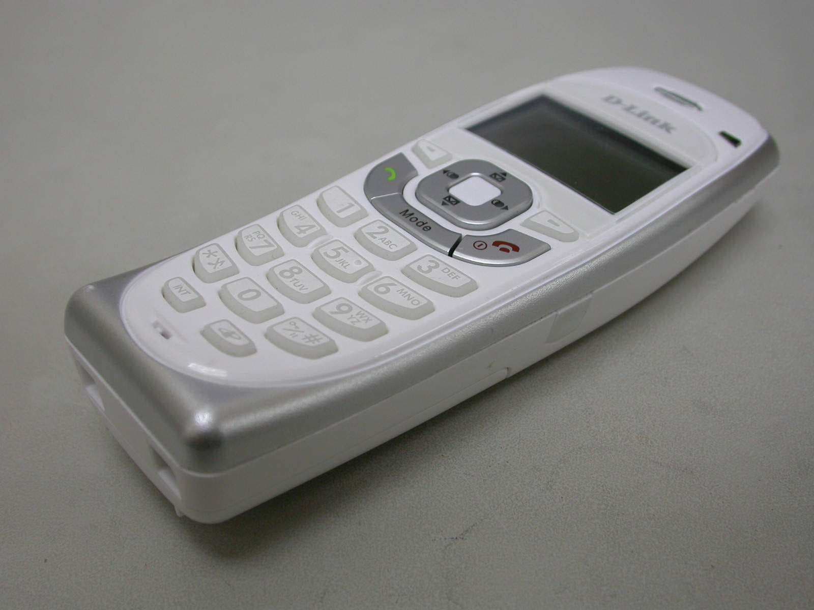
PBWDT19R35H
Apr 02, 2008US DECT HANDSET UNIT
Equipment Class
PUE - Part 15 Unlicensed PCS portable Tx held to ear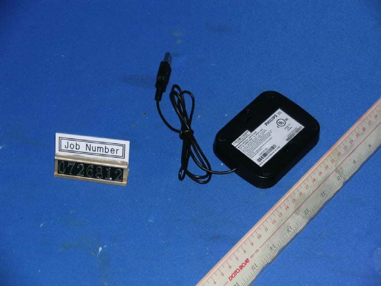
PBWUB19R51
Feb 24, 20081.9GHZ USB PHONE
Equipment Class
JBP - Part 15 Class B Computing Device Peripheral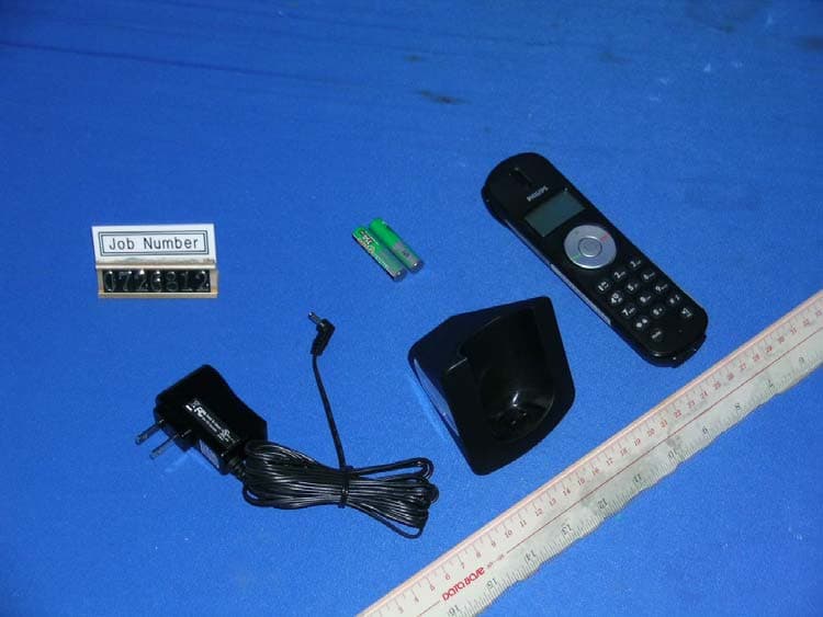
PBWUB19R51H
Feb 24, 20081.9GHZ USB PHONE- HANDSET
Equipment Class
PUE - Part 15 Unlicensed PCS portable Tx held to ear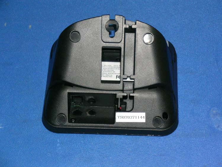
PBWDT19R51
Jan 28, 20081.9GHz cordless phone
Equipment Class
PUB - Part 15 Unlicensed PCS Base Station