PBWDS24R29VOIP HANDSET
Ascalade Technologies, Inc.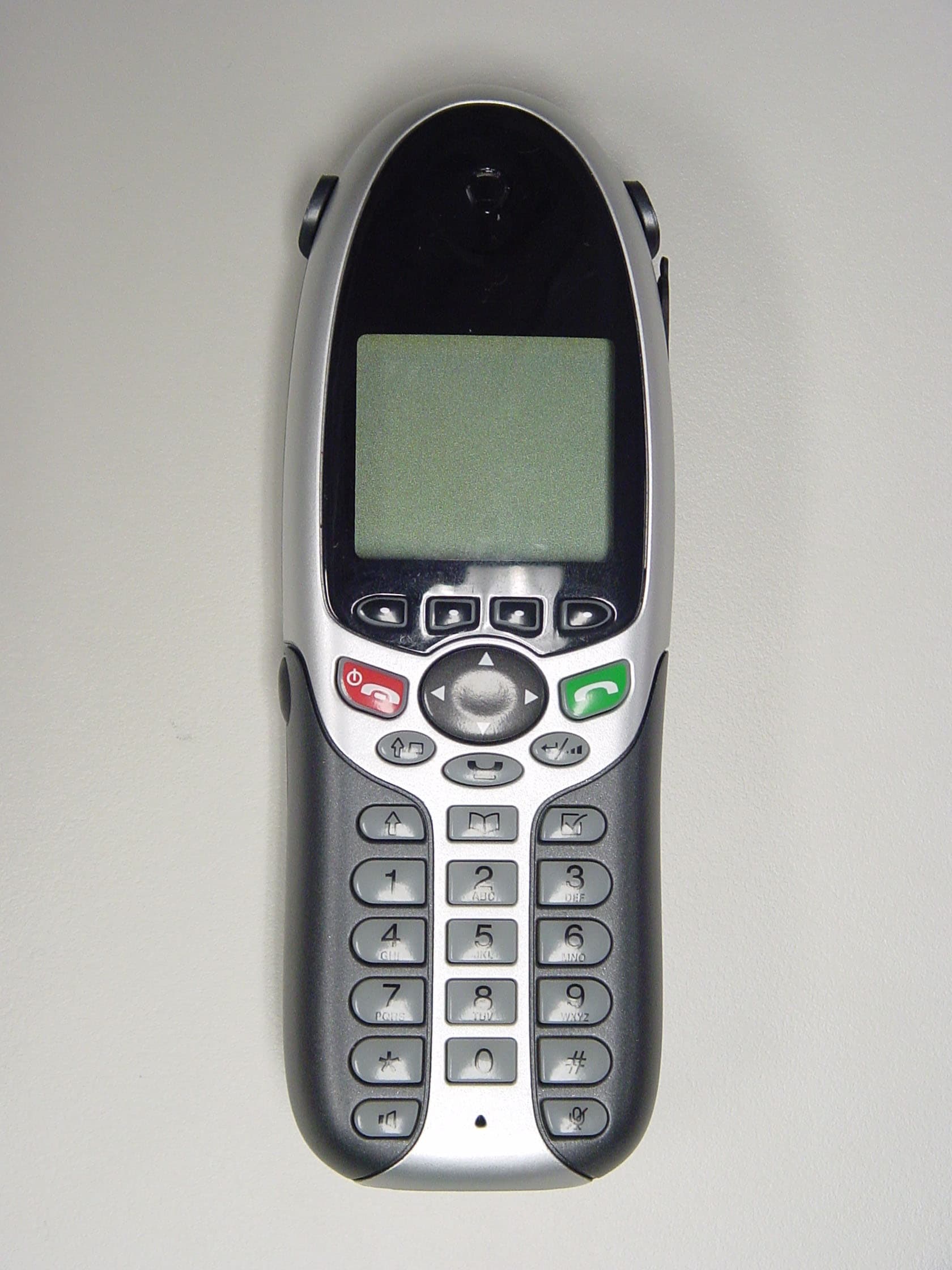
Click to zoom
Application Details
- Equipment Class
- DTS - Digital Transmission System
- Date of Grant
- Oct 28, 2004
- Application Purpose
- Original Equipment
- Date of Application
- Oct 28, 2004
- Equipment Note
- VOIP HANDSET
- Frequency Range
- 2412.00000000 - 2462.00000000
- Company
- Ascalade Technologies, Inc.
- Country
- Canada
Documents & Files
Document Text
Text extracted from the exhibit documents filed with the FCC. Open a document above to read the original.
Users Manual
The Full-Featured IP Telephone Solution Strata Wireless IP Telephone Quick Reference Guide CIX-QR-WIPT2000.book Page 0 Tuesday, September 14, 2004 5:20 PM Draft - Wireless IPT Quick Reference Guide 10/04 © Copyright 2004 Toshiba America Information Systems, Inc. Digital Solutions Division All rights reserved. No part of this manual, covered by the copyrights hereon, may be reproduced in any form or by any means—graphic, electronic, or mechanical, including recording, taping, photocopying, or information retrieval systems— without express written permission of the publisher of this material. Strata is a registered trademark of Toshiba Corporation. Trademarks, registered trademarks, and service marks are the property of their respective owners. Safety and Compliance Instructions Review the Safety and Compliance Instructions sheet found in your Wireless IP Telephone box and all the other product safety instructions that are included on the product. Publication Information Toshiba America Information Systems, Inc., Digital Solutions Division, reserves the right, without prior notice, to revise this information publication for any reason, including, but not limited to, utilization of new advances in the state of technical arts or to simply change the design of this document. Further, Toshiba America Information Systems, Inc., Digital Solutions Division, also reserves the right, without prior notice, to make such changes in equipment design or components as engineering or manufacturing methods may warrant. CIX-QR-WIPT2-VA - Draft 3 Version A, October 2004 Printed in China CIX-QR-WIPT2000.book Page 1 Tuesday, September 14, 2004 5:20 PM Draft - Wireless IPT Quick Reference Guide 10/04 i Contents Introduction.................................................................... 1 Packaging List................................................................ 1 Battery Charging............................................................ 2 Spare Battery Pack......................................................... 3 Belt Clip ......................................................................... 3 Headset (Optional) ......................................................... 4 Strata Wireless IP Telephone......................................... 4 Setup for New Users ...................................................... 5 Vibrate Mode ................................................................. 5 What’s My Line? ........................................................... 6 Which Outgoing/Incoming Call Features Do I Have?... 6 Which Codes Do I Use?................................................. 7 Unlock Telephone.......................................................... 7 Soft Keys........................................................................ 7 Flexible Buttons ............................................................. 8 Making a Call................................................................. 9 Answering a Call .......................................................... 9 Account Code Calls ....................................................... 9 Call Transfer ................................................................ 10 Conference Calls.......................................................... 10 Hold ............................................................................. 12 Call Forward - Any Calls............................................. 13 Call Park Orbits ........................................................... 13 Call Pickup................................................................... 14 Echo Cancel ................................................................. 14 Paging .......................................................................... 14 Redial ........................................................................... 15 Speed Dial.................................................................... 15 One Touch Buttons ...................................................... 15 Voice Mail Call Monitor.............................................. 16 Voice Mail - Direct Transfer ....................................... 16 Volume Control ........................................................... 16 LCD Features ............................................................... 17 CIX-QR-WIPT2000.book Page i Tuesday, September 14, 2004 5:20 PM 1 Draft - Wireless IPT Quick Reference Guide 10/04 Introduction This quick reference guide applies to Toshiba Strata Wireless IP Telephone (WIPT) connected to a Strata CIX/CTX system. The WIPT handset supports 11 fixed buttons, four LCD Control Buttons/Soft Keys and 10 Flexible buttons (Programmable buttons). This telephone has 160 x 100 pixel Graphic LCD Display which supports Toshiba’s two-line by 24-character and 10 Flexible Buttons display. The LCD also includes a Local Status bar update. See “Strata Wireless IP Telephone” on page 4. Important!Your handset may not have all of the features mentioned in this manual. See your Strata CIX/CTX System Administrator for more information. Use the check boxes or blank lines to enter the variable selections for your telephone. Packaging List Your Toshiba WIPT package includes the following: CAUTION Do not use cleansers that contain benzene, paint thinner, alcohol or other solvents on the telephone charger’s rubber feet. The color of the rubber may transfer to the desk or mounting surface. WIPT2000Strata Wireless IP Handset WIPT2000A-BTTBattery pack WIPT2000A-CHGCharger for handset and spare battery pack WIPT2000A-CLPBelt clip WIPT2000A-ACA-AAC adapter for the Charger (North America) WIPT2000A-CVRBattery cover plate CIX-QR-WIPT2-VAQuick reference guide (QRG) CIX-SC-WIPT2-VASafety and Compliance Instruction Sheet CIX-QR-WIPT2000.book Page 1 Tuesday, September 14, 2004 5:20 PM Draft - Wireless IPT Quick Reference Guide 10/04 2 Battery Charging Important!You must charge the battery continuously for five hours before using the telephone for the first time. ³To …
Text truncated - open the document above for the full version.
Cover Letter(s)
Equipment Authorization Division Office of Engineering and Technology Federal Communications Commission 7435 Oakland Mills Road Columbia, MD 21046 Date: October 28, 2004 Ref: FCC ID: PBWDS24R29 Request for Confidentiality Dear Sirs: With regard to the referenced application, ARKON Networks Inc. is requesting confidentiality of certain sections of the accompanying documents. The documents for which ARKON is requesting confidentiality are: ß Block Diagrams ß Schematic Diagrams ß Theory of Operation / Circuit Descriptions. This request is made under the provisions of Section 0.457(d) of the Commission’s Rules, and Section 552(b)(4) of the Freedom of Information Act. The material for which confidentiality is requested falls within the scope of Section 552(b)(4) as trade secrets and includes material covered by Section 0.459 of the Commission’s Rules. Sincerely, Kevin Yau Quality Manager
External Photos
R029pcbaPh10.pdf R029pcbaPh10.pdf
ID Label/Location Info
D008 Label & Engraving FCC ID: PBWDS24R29 IC: 3842A-D008 MADE IN CHINA FABRIQUE EN CHINE TO REDUCE RISK OF FIRE OR PERSONAL INJURY, USE ONLY NiMH RECHARGEABLE BATTERY 3.6V 1800 mAh. POUR REDUIRE LE RISQUE DU FEU OU DE BLESSURES, UTILISEZ SEULEMENT LA BATTERIE RECHARGEABLE 3.6V 1800 mAh DE NiMH. RECHARGEABLE BATTERY MUST BE RECYCLED OR DISPOSED OF PROPERLY. LOT NO. D9 MODEL/MODELE D008 MAC: 123456 789000 S/N: D8DA 12345 Q.C. PASSED Enlarged Label Details CAUTION
RF Exposure Info
Wireless LAN and your Health Wireless LAN products, like other radio devices, emit radio frequency electromagnetic energy. The level of energy emitted by Wireless LAN devices however is far much less than the electromagnetic energy emitted by wireless devices like for example mobile phones. Because Wireless LAN products operate within the guidelines found in radio frequency safety standards and recommendations, TOSHIBA believes Wireless LAN is safe for use by consumers. These standards and recommendations reflect the consensus of the scientific community and result from deliberations of panels and committees of scientists who continually review and interpret the extensive research literature. In some situations or environments, the use of Wireless LAN may be restricted by the proprietor of the building or responsible representatives of the organization. These situations may for example include: •Using the Wireless LAN equipment on board of airplanes, or •In any other environment where the risk of interference to other devices or services is perceived or identified as harmful. If you are uncertain of the policy that applies on the use of wireless devices in a specific organization or environment (e.g. airports), you are encouraged to ask for authorization to use the Wireless LAN device prior to turning on the equipment. COMPLIANCE INFORMATON FOR US FEDERAL COMMUNICATIONS COMMISSION REQUIREMENTS Interference This equipment has been tested and found to comply with the limits for a class B digital device, pursuant to Part 15 of the FCC Rules. Operation is subject to the following two conditions: (1) This device may not cause interference, and (2) This device must accept any interference, including interference that may cause undesired operation of the device. This equipment generates, uses and can radiate radio frequency energy and, if not installed and used in accordance with the instructions, may cause harmful interference to radio communications. However, there is no guarantee that interference will not occur in a particular installation. If this equipment does cause harmful interference to radio or television reception, which can be determined by turning the equipment off and on, the user is encouraged to try to correct the interference by one or more of the following measures: 1.Re-orient or relocate the receiving antenna. 2.Increase the distance between the equipment and receiver. 3.Connect the equipment into an outlet on a circuit different from that to which the receiver is connected. 4.Consult the dealer or an experienced radio/TV technician for help. Caution Users should ensure for their own protection that the electrical ground connections of the power utility, telephone lines and internal metallic water pipe system, if present, are connected together. This precaution may be particularly important in rural areas. Do not attempt to repair or modify this equipment. Repairs to certified equipment should be made by an authorized maintenance facility designated by the supplier. Any repairs or alternations made by the user to the equipment may render the equipment void in product warranty and compliance. This could also void the user's authority to operate the equipment. RF Radiation Exposure For body worn operation, this phone has been tested and meets the FCC RF exposure guidelines when used with the belt clip supplied with this product. Use of other accessories may not ensure compliance with FCC RF exposure guidelines. Noise Electrical pulse noise is present at one time or another. This is most intense during electrical storms. Certain kinds of electrical equipment, such as light dimmers, fluorescent bulbs, motors, fans, etc., also generate pulse noise. Because radio frequencies are susceptible to this, you may on occasion hear pulse noise through the receiver. This is usually only a minor annoyance and should not be interpreted as a defect of the unit. COMPLIANCE INFORMATON FOR CANADA INDUSTRY CANADA REQUIREMENTS Notice: The term “IC:” before the certification/registration number signifies that Industry Canada technical specifications were met. This certification means that the equipment meets certain radio communications, and operational requirements. Users should ensure for their own protection that the electrical ground connections of the power utility, and internal metallic water pipe system, if present, are connected together. This precaution may be particularly important in rural areas. Caution: Users should not attempt to make such connections themselves, but should contact the appropriate electric inspection authority, or electrician, as appropriate. Do not attempt to repair or modify this equipment. Repairs to certified equipment should be made by an authorized maintenance facility designated by the supplier. Any repairs or alternations made by the user to the equipment may render the equipment void in product warranty and compliance. Caution: Changes or modifications not expressly approved by the party responsible for its compliance could void the user’s authority to operate the equipment. Interference This equipment has been tested and found to comply with the limits for a class B digital device, pursuant to Specification ICES-003 of Industry Canada. Operation is subject to the following two conditions: (1) This device may not cause interference, and (2) This device must accept any interference, including interference that may cause undesired operation of the device. This device complies also with RSS-210 of Industry Canada. This equipment generates, uses and can radiate radio frequency energy and, if not installed and used in accordance with the instructions, may cause harmful interference to radio communications. However, there is no guarantee that interference will not occur in a particular installation. If this equipment does cause harmful interference to residential radio or television reception, which can be determined by turning the equipment off and on, the user i…
Text truncated - open the document above for the full version.
Test Report
TIMCO ENGINEERING INC. 849 NW State Road 45 Newberry, Florida 32669 http://www.timcoengr.com 888.472.2424 F 352.472.2030 email: [email protected] APPLICANT: ARKON NETWORKS INC. FCC ID: PBWDS24R29 REPORT #: T:\A\ARKON_NETWORKS\1643AUT4\1643AUT4TestReport.doc COVER PAGE Test Report Product Name: VOIP HANDSET FCC ID: PBWDS24R29 Applicant: ARKON NETWORKS INC. 12051 RIVERSIDE WAY RICHMOND, BC V6W 1K7 CANADA Date Receipt: OCTOBER 7, 2004 Date Tested: OCTOBER 21, 2004 TIMCO ENGINEERING INC. 849 NW State Road 45 Newberry, Florida 32669 http://www.timcoengr.com 888.472.2424 F 352.472.2030 email: [email protected] APPLICANT: ARKON NETWORKS INC. FCC ID: PBWDS24R29 REPORT #: T:\A\ARKON_NETWORKS\1643AUT4\1643AUT4TestReport.doc TABLE OF CONTENTS TABLE OF CONTENTS TEST REPORT CONTAINING: PAGE 1.............LIST OF TEST EQUIPMENT PAGE 2.............TEST PROCEDURES PAGE 3.............POWERLINE CONDUCTED INTERFERENCE PAGE 4-5...........POWERLINE CONDUCTED PLOTS PAGE 6.............OCCUPIED BANDWIDTH AND 6 dB BANDWIDTH PLOT PAGE 7.............POWER OUTPUT PAGE 8.............SPURIOUS EMISSIONS AT ANTENNA TERMINALS DATA PAGE 9.............METHOD OF MEASURING RF CONDUCTED AND PAGE 10............RADIATION INTERFERENCE TEST DATA PAGE 11............METHOD OF MEASURING RADIATED SPURIOUS EMISSIONS PAGE 12-13.........RADIATED SPURIOUS EMISSIONS INTO ADJACENT RESTRICTED BANDS PAGE 14............POWER SPECTRAL DENSITY EXHIBITS INCLUDED: REQUEST FOR CONFIDENTIALITY LETTER BLOCK DIAGRAM SCHEMATICS USERS MANUAL LABEL SAMPLE LABEL LOCATION EXTERNAL PHOTOGRAPHS INTERNAL PHOTOGRAPHS OPERATIONAL DESCRIPTION TEST SET UP PHOTOGRAPHS TIMCO ENGINEERING INC. 849 NW State Road 45 Newberry, Florida 32669 http://www.timcoengr.com 888.472.2424 F 352.472.2030 email: [email protected] APPLICANT: ARKON NETWORKS INC. FCC ID: PBWDS24R29 REPORT #: T:\A\ARKON_NETWORKS\1643AUT4\1643AUT4TestReport.doc Page 1 of 14 EMC Equipment List Device Manufacturer Model Serial Number Cal/Char Date Due Date 3/10-Meter OATS TEI N/A N/A Listed 3/27/04 3/26/07 3-Meter OATS TEI N/A N/A Listed 1/13/03 1/12/06 Biconnical Antenna Eaton 94455-1 1057 CAL 3/18/03 3/18/05 Biconnical Antenna Eaton 94455-1 1096 CAL 8/17/04 8/17/06 Biconnical Antenna Electro- Metrics BIA-25 1171 CAL 4/26/01 4/26/03 Double- Ridged Horn Antenna Electro- Metrics RGA-180 2319 CAL 2/17/03 2/17/05 LISN Electro- Metrics ANS-25/2 2604 CAL 8/27/04 8/27/06 LISN Electro- Metrics EM-7820 2682 CAL 3/12/03 3/12/05 Log- Periodic Antenna Eaton 96005 1243 CAL 5/8/03 5/8/05 TIMCO ENGINEERING INC. 849 NW State Road 45 Newberry, Florida 32669 http://www.timcoengr.com 888.472.2424 F 352.472.2030 email: [email protected] APPLICANT: ARKON NETWORKS INC. FCC ID: PBWDS24R29 REPORT #: T:\A\ARKON_NETWORKS\1643AUT4\1643AUT4TestReport.doc Page 2 of 14 TEST PROCEDURE GENERAL: This report shall NOT be reproduced except in full without the written approval of TIMCO ENGINEERING, INC. POWER LINE CONDUCTED INTERFERENCE: The procedure used was ANSI STANDARD C63.4- 1992 using a 50uH LISN. Both lines were observed with the UUT transmitting. The bandwidth of the spectrum analyzer was 10kHz with an appropriate sweep speed. The ambient temperature of the UUT was 76°F with a humidity of 55%. BANDWIDTH 6.0dB: The measurements were made with the spectrum analyzer's resolution bandwidth (RBW)=1.0MHz and the video bandwidth (VBW) =3.0MHz and the span set as shown on plot. POWER OUTPUT: The RF power output was measured at the antenna feed point using a peak power meter. ANTENNA CONDUCTED EMISSIONS: The RBW=100KHz, VBW=300KHz and the span set to 10.0MHz and the spectrum was scanned from 30MHz to the 10 th Harmonic of the fundamental. Above 1.0GHz the resolution bandwidth was 1.0MHz and the VBW = 3.0MHz and the span to 50MHz. RADIATION INTERFERENCE: The test procedure used was ANSI STANDARD C63.4-1992 using a HEWLETT PACKARD spectrum analyzer with a pre-selector. The bandwidth (RBW) of the spectrum analyzer was 100kHz up to 1GHz and 1.0MHz above 1GHz with an appropriate sweep speed. The VBW above 1.0GHz was = 3.0MHz. The analyzer was calibrated in dB above a microvolt at the output of the antenna. The ambient temperature of the UUT was 76°F with a humidity of 55%. TIMCO ENGINEERING INC. 849 NW State Road 45 Newberry, Florida 32669 http://www.timcoengr.com 888.472.2424 F 352.472.2030 email: [email protected] APPLICANT: ARKON NETWORKS INC. FCC ID: PBWDS24R29 REPORT #: T:\A\ARKON_NETWORKS\1643AUT4\1643AUT4TestReport.doc Page 3 of 14 APPLICANT: ARKON NETWORKS INC. FCC ID: PBWDS24R29 NAME OF TEST: POWER LINE CONDUCTED INTERFERENCE RULES PART NO.: 15.107(a) REQUIREMENTS: QUASI-PEAK AVERAGE .15 – 0.5 MHz 66-56 dBuV 56-46 dBuV 0.5 – 5.0 56 46 5.0 – 30. 60 50 TEST PROCEDURE: ANSI STANDARD C63.4-1992. The spectrum was scanned from .15 to 30 MHz. TEST DATA: THE PLOTS ON THE FOLLOWING PAGES REPRESENT THE EMISSIONS TAKEN FOR THIS DEVICE. TEST RESULTS: Both lines were observed. The measurements indicate that the unit DOES appear to meet the FCC requirements for this class of equipment. TIMCO ENGINEERING INC. 849 NW State Road 45 Newberry, Florida 32669 http://www.timcoengr.com 888.472.2424 F 352.472.2030 email: [email protected] APPLICANT: ARKON NETWORKS INC. FCC ID: PBWDS24R29 REPORT #: T:\A\ARKON_NETWORKS\1643AUT4\1643AUT4TestReport.doc Page 4 of 14 POWER LINE CONDUCTED LINE 1 TIMCO ENGINEERING INC. 849 NW State Road 45 Newberry, Florida 32669 http://www.timcoengr.com 888.472.2424 F 352.472.2030 email: [email protected] APPLICANT: ARKON NETWORKS INC. FCC ID: PBWDS24R29 REPORT #: T:\A\ARKON_NETWORKS\1643AUT4\1643AUT4TestReport.doc Page 5 of 14 POWER LINE CONDUCTED LINE 2 TIMCO ENGINEERING INC. 849 NW State Road 45 Newberry, Florida 32669 http://www.timcoengr.com 888.472.2424 F 352.472.2030 email: [email protected] APPLICANT: ARKON NETWORKS INC. FCC ID: PBWDS24R29 REPORT #: T:\A\ARKON_NETWORKS\1643AUT4\1643AUT4TestReport.doc Page 6 of 14 APPLICANT: ARKON NETWORKS INC. FCC ID: PBWDS24R29 NAME OF TEST: 6.0dB BANDWIDTH RULES PART NO.: 15.247(a)(2) REQ…
Text truncated - open the document above for the full version.
Contact Information
Applicant
James Tung(Senior Engineering Manager)
Test Firm
Timco Engineering, Inc.S Sanders
Technical Specifications
| # | Rule Parts | Frequency Range | Power Output |
|---|---|---|---|
| 1 | 15C | 2.41 GHz - 2.46 GHz | 24.00 mW |
Other Applications from Ascalade Technologies, Inc.
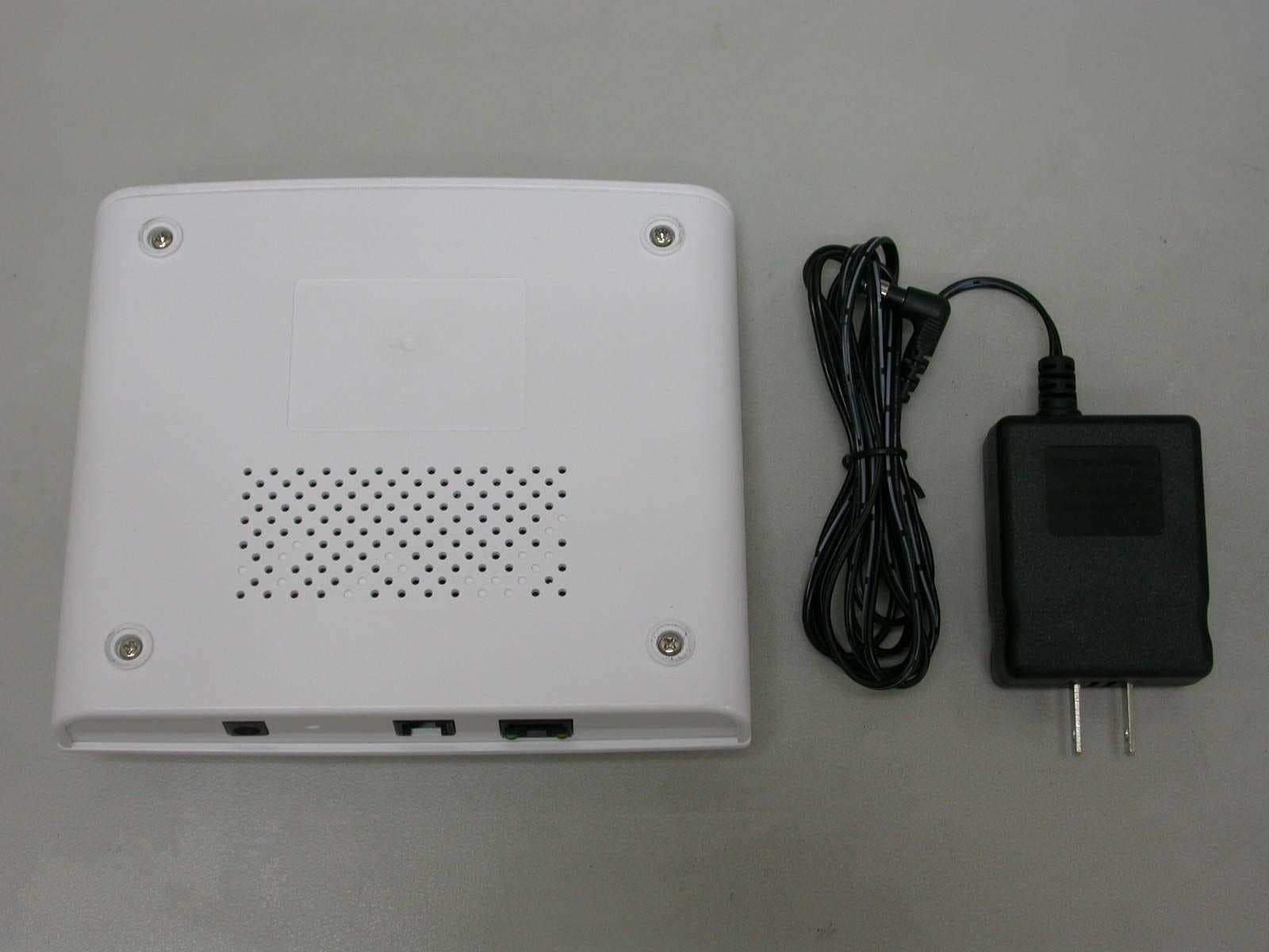
PBWDT19B232
Apr 02, 2008US DECT BASE UNIT
Equipment Class
PUB - Part 15 Unlicensed PCS Base Station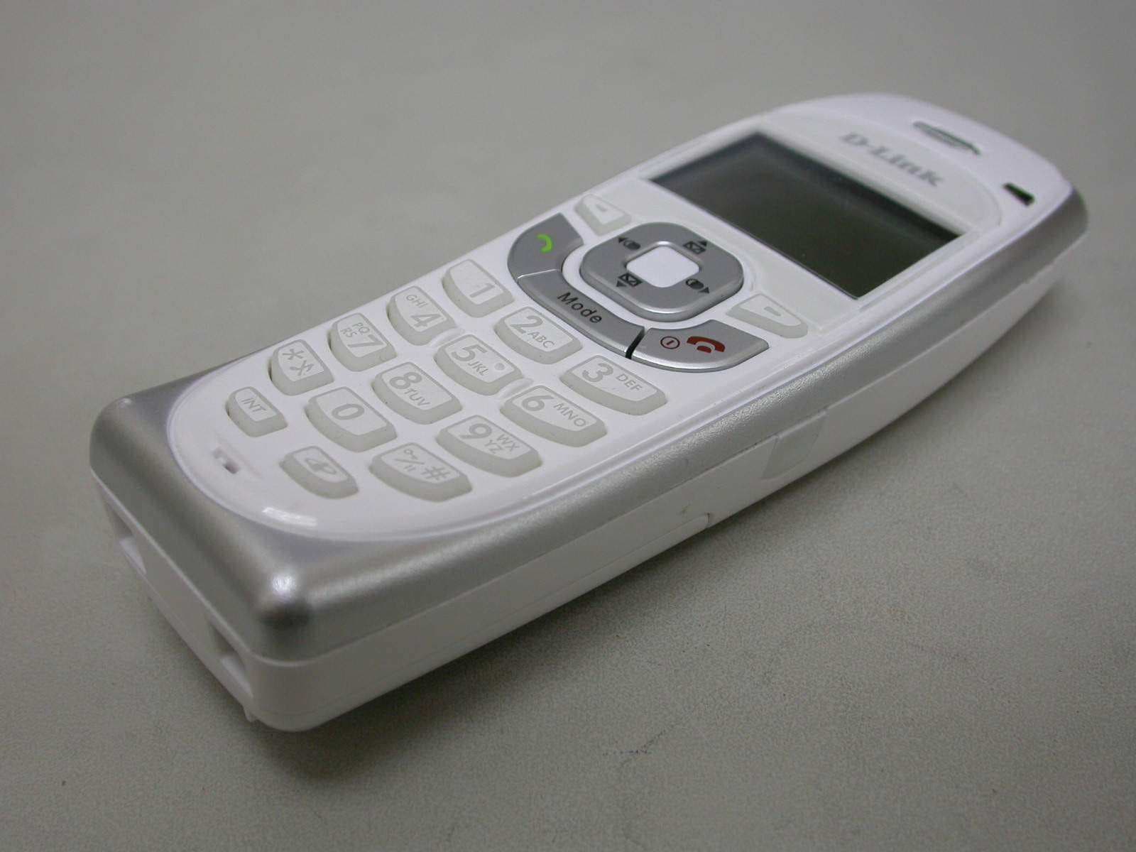
PBWDT19R35H
Apr 02, 2008US DECT HANDSET UNIT
Equipment Class
PUE - Part 15 Unlicensed PCS portable Tx held to ear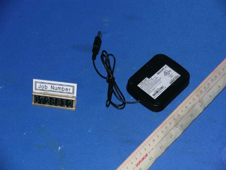
PBWUB19R51
Feb 24, 20081.9GHZ USB PHONE
Equipment Class
JBP - Part 15 Class B Computing Device Peripheral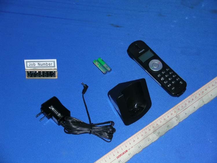
PBWUB19R51H
Feb 24, 20081.9GHZ USB PHONE- HANDSET
Equipment Class
PUE - Part 15 Unlicensed PCS portable Tx held to ear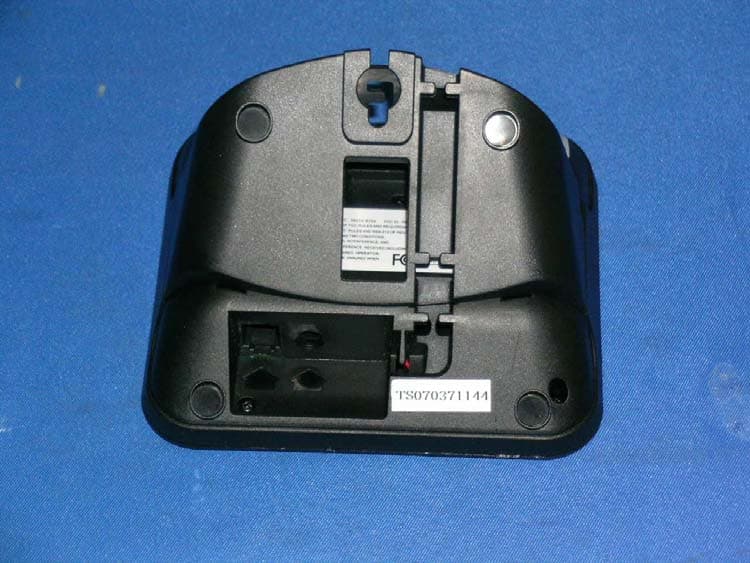
PBWDT19R51
Jan 28, 20081.9GHz cordless phone
Equipment Class
PUB - Part 15 Unlicensed PCS Base Station