PD4PB01RRemote Control Security Receiver
Lentek International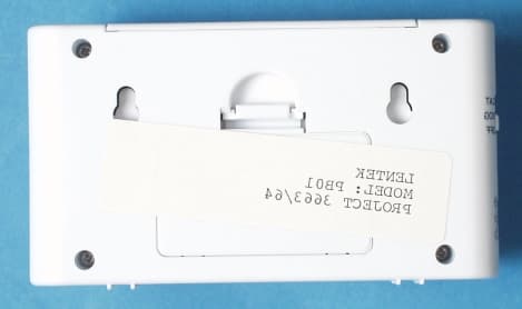
Click to zoom
Application Details
- Equipment Class
- CYY - Communications Receiver used w/Pt 15 Transmitter
- Date of Grant
- Dec 10, 2000
- Application Purpose
- Original Equipment
- Date of Application
- Dec 10, 2000
- Equipment Note
- Remote Control Security Receiver
- Frequency Range
- 314.50000000 - 315.50000000
- Company
- Lentek International
- Country
- United States
Documents & Files
Document Text
Text extracted from the exhibit documents filed with the FCC. Open a document above to read the original.
Test Report
ENGINEERING STATEMENT IN REGARD TO MEASUREMENTS ON LENTEK INTERNATIONAL PB01 RECEIVER FCC ID: PD4PB01R Super-Regenerative Receiver A. INTRODUCTION Hyak Laboratories Inc. has been authorized by Lentek International to perform measurements on the PB01 receiver to determine compliance with FCC Rules, Part 15 Subpart B, Para. 15.109. The PB01 is designed to operate as part of a pet security system. It operates at a nominal 315 MHz frequency. The receiver, constructed on an etched circuit card, is powered by a 9 volt battery, or external 177 Vac power module. (A transmitter, FCC ID: PC7PB01T, is a part of the system.) B. DESCRIPTION OF MEASUREMENT FACILITIES A description of the Hyak Laboratories Inc. radiation test facility is a matter of record with the FCC. The facility was accepted for radiation measurements on October 1, 1976, and is currently listed as an accepted site. C. DESCRIPTION OF MEASUREMENT PROCEDURE: RADIATED MEASUREMENTS Measurements of receiver radiation field strength were made using ANSI 63.4 (1992) as the test procedure. Measurements were made with 3 meter spacing between the receiver under test and the test equipment antenna. The antenna connected to the receiver under test was operated with its internal, integral antenna. 2 C. DESCRIPTION OF MEASUREMENT PROCEDURE: RADIATED MEASUREMENTS (Continued) The receiver under test was placed on a rotatable table approximately one meter in height. Measurement of field strength was made through use of TEK 494P and Advantest R3361A spectrum analyzers in conjunction with a HP 8447D wide band, low noise preamp. Compliance Designs Bi- conical calibrated dipoles were used as the test antennas in the 25-1000 MHz range. Above 1 GHz the Tektronix 494P spectrum analyzer was used with a an EMCO 3115 calibrated horn antenna between 1 and 4 GHz. For each spurious emission identified between 30 to 2000 MHz, the test sample was rotated for maximum pickup, the test antenna varied in elevation, and the test antenna polarization shifted between horizontal to vertical in order to maximize observed signals. Spurious emissions within the 30 - 1000 MHz band were measured with the receiver cohered and a peak-responding detector employed. Above 1 GHz, the Tektronix 494P spectrum analyzer, a peak-responding instrument, with 1 MHz RBW, and no video filtering was used. The measurement procedure included recording the worst-case field strength for receiving antenna polarization, test antenna height variation from 3 feet to 10 feet and test sample rotation. The sample was measured in three orientation planes. The spectrum was checked from 30 to 2000 MHz. All emissions not reported were more than 20 dB below the permitted level or below the applicable limits but obscured by ambient or instru- mentation noise. Tabulation of the measurements are shown in Table 1. The forbidden band frequencies of 15.205 were specifically searched. D. REPORT OF RADIATED MEASUREMENTS Table 1 lists the frequency and amplitude of all signals observed from 30 to 2000 MHz that were within 20 dB of the limits of FCC Rules. 3 TABLE 1 RADIATED SPURIOUS EMISSIONS Measured at 3 meters PART 15(B) PARA. 15.109 Frequency Frequency To Which of Meter Antenna Field 1 Tuned Emission Reading Factor Intensity FCC Limit dB to (MHz) (MHz) (dBm) (dB) uV/m @ 3m uV/m @ 3m Limit 315.000 311.600 -93.6 21.7 57 200 -11 315.000 628.200 -102.8 28.5 43 200 -13 315.000 942.300 -102.4 32.6 72 200 - 8.8 315.000 1256.400 -102.4 25.1 31* 500 -24 315.000 1570.500 -99.2 26.1 50* 500 -20 315.000 1884.600 -94.8 27.7 99 500 -14 315.000 2198.700 -96.0 28.8 98 500 -14 315.000 2512.800 -94.8 29.6 123 500 -12 315.000 2826.900 -94.8 30.4 135 500 -11 315.000 3141.000 -94.4 31.2 155 500 -10 Note 1: uV/m = Log -1dBu/m 20 dBu = dBm + antenna factor + 107 All other emissions were 20 dB or more below FCC limits or, for forbidden band, below ambient or instrumentation noise level. Cohered, peak-detector Measured in three planes of orientation. FCC ID: 4 RADIATED FIELD INTENSITY FCC ID: PD4PB01R TABLE 1 E. POWER LINE CONDUCTED MEASUREMENTS Using a 50uH LISN, AC power line conducted radio frequency voltage was measured using an Advantest R3361A spectrum analyzer. Measurements were made from .45 to 30 MHz using CISPR quasi-peak detector with 9 kHz resolution bandwidth. Data in dBuV, are shown in Figures 1 and 2 for right and left LISN port respectively. A 120 second scan time was used. F. FORBIDDEN BAND MEASUREMENTS All forbidden bands of 15.205 from 73 MHz to 2 GHz were searched and any signals above ambient noise or interference levels are shown in Table 1. G. STATEMENT Technical test data are from tests performed by me or under my supervision. My qualifications are a matter of record with the Federal Communications Commission. I personally attest to the accuracy of the test data submitted as a part of this engineering statement. __________________________________ Rowland S. Johnson Dated: November 9, 2000 5 FIGURE 1 6 AC LINE CONDUCTED FCC ID: PD4PB01R FIGURE 1 (RIGHT LISN) FIGURE 2 7 AC LINE CONDUCTED FCC ID: PD4PB01R FIGURE 2 (LEFT LISN)
Contact Information
Applicant
Matt Spiro
Test Firm
Hyak Laboratories, Inc.Rowland Johnson
703-451-1188
Technical Specifications
| # | Rule Parts | Frequency Range | Power Output |
|---|---|---|---|
| 1 | 15B | 314.5 MHz - 315.5 MHz | - |
Other Applications from Lentek International
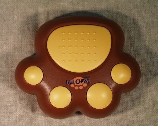
PD4PP10
Apr 19, 2001Pet Door Chime
Equipment Class
DXX - Part 15 Low Power Communication Device Transmitter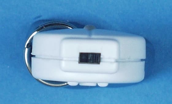
PD4PB01T
Dec 10, 2000Remote Control Security Transmitter
Equipment Class
DSC - Part 15 Security/Remote Control Transmitter