PD5-RV132WWireless-N VPN Router
Delta Electronics, Inc.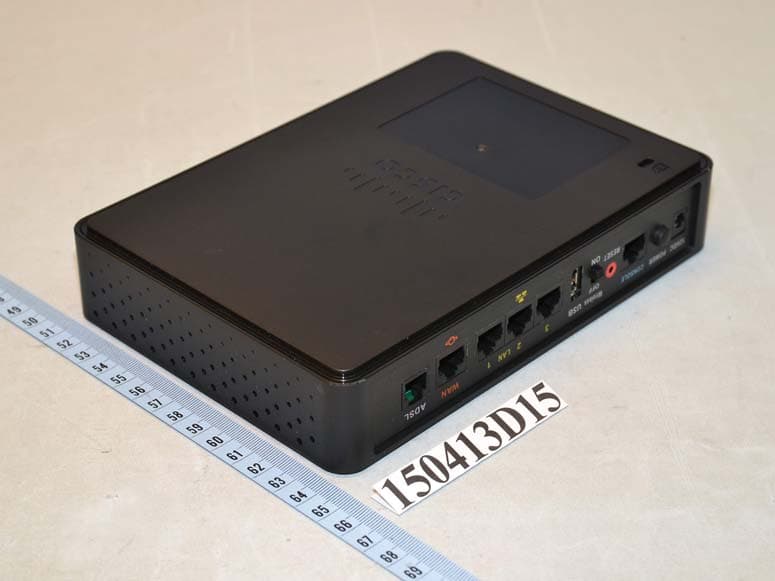
Click to zoom
Application Details
- Equipment Class
- DTS - Digital Transmission System
- Date of Grant
- Jul 14, 2015
- Application Purpose
- Original Equipment
- Date of Application
- Jul 14, 2015
- Equipment Note
- Wireless-N VPN Router
- Frequency Range
- 2412.00000000 - 2462.00000000
- Company
- Delta Electronics, Inc.
- Country
- Taiwan
Documents & Files
Document Text
Text extracted from the exhibit documents filed with the FCC. Open a document above to read the original.
Users Manual
Quick Start Guide Cisco RV132W ADSL2+ Wireless-N VPN Router Package Contents •Cisco RV132W ADSL2+ Wireless-N VPN Router •Power Adapter •Ethernet Cable •This Quick Start Guide •Pointer Card •Technical Support Contact Card •Console Cable •RJ-11 Cable 2Cisco RV132W ADSL2+ Wireless-N VPN Router Quick Start Guide Welcome Thank you for choosing the Cisco RV132W ADSL2+ Wireless-N VPN Router. The RV132W provides business class DSL connectivity for SOHO, small businesses and remote professionals. This guide describes how to physically install your Cisco RV132W and launch the web-based Device Manager. Installing Cisco RV132W To prevent the device from overheating or being damaged: • Ambient Temperature—Do not operate the device in an area that exceeds an ambient temperature of 104°F (40°C). • Air Flow—Be sure that there is adequate air flow around the device. If wall mounting the wireless access point, make sure the heat dissipation holes are to the side. • Mechanical Loading—Be sure that the device is level and stable to avoid any hazardous conditions and that it is secure to prevent it from sliding or shifting out of position. Do not place anything on top of the wireless access point, as excessive weight might damage it. Place the Cisco RV132W unit vertically into the stand with the four rubber feet. 1 Cisco RV132W ADSL2+ Wireless-N VPN Router Quick Start Guide3 Cisco RV132W Features Front Panel PowerSolid green when the device is powered on and booted. Flashing green when the device is booting or loading the firmware. Solid red when the device fails to reboot, or system error, or is in firmware recovery mode. Off when the device is powered off. InternetOff when the ADSL2+/WAN LED is OFF. Solid green when the device has a DSL WAN IP or Ethernet WAN IP connection. Flashing green when the device is sending or receiving data through the DSL WAN. Solid red when the device has no DSL WAN IP or Ethernet WAN IP connection. ADSL2+/ Ethernet WAN Off when the device is powered off or the device is configured to use ADSL2+/Ethernet WAN yet has no ADSL2+/Ethernet link. Solid green when the DSL link has been activated. Flashing green when the device is negotiating with the DSLAM. Solid blue when the Ethernet link is on. Flashing blue when the device is transmitting/receiving through Ethernet WAN. LAN (1-3)The numbered lights correspond to the LAN ports on the back panel. Solid green when the corresponding port is connected to a device. Flashing green when the port is sending or receiving data. WLAN 2.4GOff when the 2.4GHz wireless module is disabled. Flashing green when the wireless radio is transmitting or receiving data. Solid green when the 2.4GHz wireless module is enabled. 2 4Cisco RV132W ADSL2+ Wireless-N VPN Router Quick Start Guide Back Panel ADSL—Insert a RJ-11 cable to connect the router to the ISP DSLAM. WAN /Ethernet WAN—Connecting the device to a wide area network device, such as a cable or DSL modem. LAN (1-3)—RJ-45 device connections to link local area network devices, such as PCs, print servers, or switches, to the device. USB—Type A USB port that supports 3G/4G/LTE USB dongles. Wireless—Switch the slide button to enable or disable Wi-Fi. RESET—The RESET button has two functions: •To reboot the unit and retain the current configuration, press and hold RESET for at least 3, but no more than 10 seconds, by using a paper clip or a pen tip. •To reboot the unit and restore the factory default configuration, press and hold in the RESET button for more than 10 seconds. Changes you have made to the Cisco RV132W configuration are lost. CONSOLE— Insert the RJ-45 roll-over cable to connect the device to a console, such as PCs. POWER— The POWER button is used to turn the power on and off. 12VDC—Power port that connects the device to the provided 12VDC power adapter. VPNOff when there is no VPN tunnel defined, or all defined VPN tunnels have been disabled. Solid green when there is at least one VPN tunnel working. Solid amber when none of the enabled VPN tunnels are working. USBOff when no 3G/4G USB dongle is connected or the USB dongle is not recognized. Solid green when the 3G/4G USB dongle is recognized and currently connecting to the ISP network. Flashing green when the 3G/4G USB dongle is successfully connected to the Internet Service Provider (ISP) and the port is receiving and sending data. Solid amber when the USB dongle is recognized but fails to connect to the ISP. Cisco RV132W ADSL2+ Wireless-N VPN Router Quick Start Guide5 WARNINGConnecting a power adapter out of spec may result in hardware damage. Side Panel The side panel of the Cisco RV132W has a Kensington lock slot. You can use it to attach a cable and lock to the Cisco RV132W. 6Cisco RV132W ADSL2+ Wireless-N VPN Router Quick Start Guide Connecting the Cisco RV132W NOTE You must connect one PC with an Ethernet cable for the purpose of the initial configuration. After you complete the initial configuration, administrative tasks can be performed using a wireless connection. STEP1Power off all equipment, including the cable or DSL modem, the PC, and the Cisco RV132W. STEP2For an Ethernet WAN connection, connect one end of the Ethernet cable to your Internet access device (typically a modem), and connect the other end of the cable to the WAN port. For an ADSL connection, connect your DSL cable directly to the ADSL port on the device. If required by your Service Provider, make sure that you use an ADSL splitter. For a 3G/4G WAN connection, connect the 3G/4G USB dongle into the USB port. Then, the firewall router will detect the 3G/4G dongle and subscribe to the ISP network. Note: This application must use the specific 3G/4G dongle which is supported by the router. The 3G/4G SIM card must be configured with the user defined PIN code. STEP3Connect another Ethernet cable from one of the LAN (Ethernet) ports to the Ethernet port on the PC. STEP4Power on the cable or DSL modem and wait until the connection is active. STEP5Connect the power adapter …
Text truncated - open the document above for the full version.
External Photos
Page 1 CONSTRUCTION PHOTOS OF EUT Page 2 Page 3 Page 4
RF Exposure Info
Report No.: SA150413D15 Page No. 1 / 6 Report Format Version: 6.1.1 RF Exposure Report Report No.: SA150413D15 FCC ID: PD5-RV132W Test Model: RV132W Received Date: Apr. 13, 2015 Test Date: Apr. 27 ~ May 18, 2015 Issued Date: May 22, 2015 Applicant: Delta Networks, Inc. Address: No. 252, Shang Ying Rd., Kuei San District, Taoyuan City 33341 Taiwan Issued By: Bureau Veritas Consumer Products Services (H.K.) Ltd., Taoyuan Branch Lab Address: No. 47-2, 14th Ling, Chia Pau Vil., Lin Kou Dist., New Taipei City, Taiwan (R.O.C.) This report is for your exclusive use. Any copying or replication of this report to or for any other person or entity, or use of our name or trademark, is permitted only with our prior written permission. This report sets forth our findings solely with respect to the test samples identified herein. The results set forth in this report are not indicative or representative of the quality or characteristics of the lot from which a test sample was taken or any similar or identical product unless specifically and expressly noted. Our report includes all of the tests requested by you and the results thereof based upon the information that you provided to us. You have 60 days from date of issuance of this report to notify us of any material error or omission caused by our negligence, provided, however, that such notice shall be in writing and shall specifically address the issue you wish to raise. A failure to raise such issue within the prescribed time shall constitute your unqualified acceptance of the completeness of this report, the tests conducted and the correctness of the report contents. Unless specific mention, the uncertainty of measurement has been explicitly taken into account to declare the compliance or non-compliance to the specification. The report must not be used by the client to claim product certification, approval, or endorsement by TAF or any government agencies. Report No.: SA150413D15 Page No. 2 / 6 Report Format Version: 6.1.1 Table of Contents Release Control Record .................................................................................................................................. 3 1 Certificate of Conformity ...................................................................................................................... 4 2 RF Exposure .......................................................................................................................................... 5 2.1 Limits For Maximum Permissible Exposure (MPE) ............................................................................. 5 2.2 Mpe Calculation Formula .................................................................................................................... 5 2.3 Classification ....................................................................................................................................... 5 3 Calculation Result Of Maximum Conducted Power .......................................................................... 6 Report No.: SA150413D15 Page No. 3 / 6 Report Format Version: 6.1.1 Release Control Record Issue No. Description Date Issued SA150413D15 Original release. May 22, 2015 Report No.: SA150413D15 Page No. 4 / 6 Report Format Version: 6.1.1 1 Certificate of Conformity Product: Wireless-N VPN Router Brand: CISCO Test Model: RV132W Sample Status: Engineering sample Applicant: Delta Networks, Inc. Test Date: Apr. 27 ~ May 18, 2015 Standards: FCC Part 2 (Section 2.1091) KDB 447498 D03 IEEE C95.1 The above equipment has been tested by Bureau Veritas Consumer Products Services (H.K.) Ltd., Taoyuan Branch, and found compliance with the requirement of the above standards. The test record, data evaluation & Equipment Under Test (EUT) configurations represented herein are true and accurate accounts of the measurements of the sample’s EMC characteristics under the conditions specified in this report. Prepared by : , Date:May 22, 2015 Annie Chang / Supervisor Approved by : , Date:May 22, 2015 Rex Lai / Assistant Manage Report No.: SA150413D15 Page No. 5 / 6 Report Format Version: 6.1.1 2 RF Exposure 2.1 Limits For Maximum Permissible Exposure (MPE) Frequency Range (MHz) Electric Field Strength (V/m) Magnetic Field Strength (A/m) Power Density (mW/cm 2 ) Average Time (minutes) Limits For General Population / Uncontrolled Exposure 300-1500 ... ... F/1500 30 1500-100,000 ... ... 1.0 30 F = Frequency in MHz 2.2 MPE Calculation Formula Pd = (Pout*G) / (4*pi*r 2 ) where Pd = power density in mW/cm 2 Pout = output power to antenna in mW G = gain of antenna in linear scale Pi = 3.1416 R = distance between observation point and center of the radiator in cm 2.3 Classification The antenna of this product, under normal use condition, is at least 25cm away from the body of the user. So, this device is classified as Mobile Device. Report No.: SA150413D15 Page No. 6 / 6 Report Format Version: 6.1.1 3 Calculation Result Of Maximum Conducted Power Frequency Band (MHz) Max Power (dBm) Antenna Gain (dBi) Distance (cm) Power Density (mW/cm 2 ) Limit (mW/cm 2 ) 2412-2462 28.58 6.11 25 0.3749 1 NOTE: Directional gain = 3.10dBi + 10log(3) = 6.11dBi --- END --- Conclusion: The formula of calculated the MPE is: CPD1 / LPD1 + CPD2 / LPD2 + ......etc. < 1 CPD = Calculation power density LPD = Limit of power density WLAN 2.4GHz + WLAN 5GHz = 0.4314 + 0.5571 = 0.9885 Therefore the maximum calculation of this situation is 0.9885, which is less than the “1” limit.
Test Report
Report No.: RF150413D15 Page No. 1 / 54 Report Format Version: 6.1.1 FCC Test Report Report No.: RF150413D15 FCC ID: PD5-RV132W Test Model: RV132W Received Date: Apr. 13, 2015 Test Date: Apr. 27 ~ May 18, 2015 Issued Date: May 22, 2015 Applicant: Delta Networks, Inc. Address: No. 252, Shang Ying Rd., Kuei San District, Taoyuan City 33341 Taiwan Issued By: Bureau Veritas Consumer Products Services (H.K.) Ltd., Taoyuan Branch Lab Address: No. 47-2, 14th Ling, Chia Pau Vil., Lin Kou Dist., New Taipei City, Taiwan (R.O.C.) This report is for your exclusive use. Any copying or replication of this report to or for any other person or entity, or use of our name or trademark, is permitted only with our prior written permission. This report sets forth our findings solely with respect to the test samples identified herein. The results set forth in this report are not indicative or representative of the quality or characteristics of the lot from which a test sample was taken or any similar or identical product unless specifically and expressly noted. Our report includes all of the tests requested by you and the results thereof based upon the information that you provided to us. You have 60 days from date of issuance of this report to notify us of any material error or omission caused by our negligence, provided, however, that such notice shall be in writing and shall specifically address the issue you wish to raise. A failure to raise such issue within the prescribed time shall constitute your unqualified acceptance of the completeness of this report, the tests conducted and the correctness of the report contents. Unless specific mention, the uncertainty of measurement has been explicitly taken into account to declare the compliance or non-compliance to the specification. The report must not be used by the client to claim product certification, approval, or endorsement by TAF or any government agencies Report No.: RF150413D15 Page No. 2 / 54 Report Format Version: 6.1.1 Table of Contents Release Control Record .................................................................................................................................. 4 1 Certificate of Conformity ...................................................................................................................... 5 2 Summary of Test Results ..................................................................................................................... 6 2.1 Measurement Uncertainty ................................................................................................................... 6 2.2 Modification Record ............................................................................................................................ 6 3 General Information .............................................................................................................................. 7 3.1 General Description of EUT ................................................................................................................ 7 3.2 Description of Test Modes ................................................................................................................... 8 3.2.1 Test Mode Applicability and Tested Channel Detail ............................................................................. 9 3.3 Duty Cycle of Test Signal ................................................................................................................... 11 3.4 Description of Support Units ............................................................................................................. 12 3.4.1 Configuration of System under Test .................................................................................................. 13 3.5 General Description of Applied Standards ........................................................................................ 14 4 Test Types and Results ...................................................................................................................... 15 4.1 Radiated Emission and Bandedge Measurement ............................................................................. 15 4.1.1 Limits of Radiated Emission and Bandedge Measurement .............................................................. 15 4.1.2 Test Instruments ................................................................................................................................ 16 4.1.3 Test Procedures ................................................................................................................................. 17 4.1.4 Deviation from Test Standard ............................................................................................................ 17 4.1.5 Test Set Up ........................................................................................................................................ 18 4.1.6 EUT Operating Conditions ................................................................................................................. 18 4.1.7 Test Results ....................................................................................................................................... 19 4.2 Conducted Emission Measurement .................................................................................................. 32 4.2.1 Limits of Conducted Emission Measurement .................................................................................... 32 4.2.2 Test Instruments ................................................................................................................................ 32 4.2.3 Test Procedures ................................................................................................................................. 33 4.2.4 Deviation from Test Standard ............................................................................................................ 33 4.2.5 Test Setup .................…
Text truncated - open the document above for the full version.
Test Setup Photos
1 of 2 PHOTOGRAPHS OF THE TEST CONFIGURATION Conducted Emission Test 2 of 2 Radiated Emission Test
Contact Information
Applicant
Payton Ting(Manager)
Test Firm
Bureau Veritas CPS (H.K.) Ltd., Taoyuan BranchRichard Chen
Technical Specifications
| # | Rule Parts | Frequency Range | Power Output |
|---|---|---|---|
| 1 | 15C | 2.41 GHz - 2.46 GHz | 720.00 mW |
Other Applications from Delta Electronics, Inc.
PD5-NWA1200
Jun 16, 2026Indoor Wireless AP
Equipment Class
DTS - Digital Transmission SystemPD5-AP743
Jun 03, 2026802.11be enterprise access point
Equipment Class
NII - Unlicensed National Information Infrastructure TXPD5-AP623E
Sep 04, 2025802.11ax enterprise access point
Equipment Class
NII - Unlicensed National Information Infrastructure TX
PD5-LM-WESA04OR
Aug 01, 2021802.11 b/g/n/ac WIFI AP
Equipment Class
NII - Unlicensed National Information Infrastructure TX
PD5-NWA1000
Jul 25, 2021Wireless Access Point
Equipment Class
NII - Unlicensed National Information Infrastructure TX