PD5-WAP131Wireless-N Dual Radio Access Point with PoE
Delta Electronics, Inc.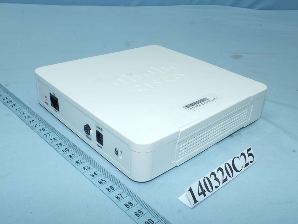
Click to zoom
Application Details
- Equipment Class
- NII - Unlicensed National Information Infrastructure TX
- Date of Grant
- Jul 03, 2014
- Application Purpose
- Original Equipment
- Date of Application
- Jul 02, 2014
- Equipment Note
- Wireless-N Dual Radio Access Point with PoE
- Frequency Range
- 5745.00000000 - 5825.00000000
- Company
- Delta Electronics, Inc.
- Country
- Taiwan
Documents & Files
Document Text
Text extracted from the exhibit documents filed with the FCC. Open a document above to read the original.
Users Manual
Americas Headquarters: Cisco Systems, Inc., 170 West Tasman Drive, San Jose, CA 95134-1706 USA REVIEW DRAFT—CISCO CONFIDENTIAL Regulatory Compliance and Safety Information for the Cisco WAP131 Wireless-N Dual Radio Access Point with PoE and Cisco WAP351 Wireless-N Dual Radio Access Point with 5 Ports Switch (EMC Class B Devices) This document provides domestic and international regulatory compliance and safety information for the Cisco WAP131 Wireless-N Dual Radio Access Point with PoE and Cisco WAP351 Wireless-N Dual Radio Access Point with 5 Ports Switch (EMC Class B Devices). Use this document in conjunction with the documentation available online for the Wireless Access Points. This document includes the following sections: •Translated Safety Warnings •European Directives •Statement 2002—Declaration of Conformity with Regard to the Directives 2006/95/EC and 2004/108/EC •China RoHS Table w/Note •EMC Class B Notices and Warnings •Japanese Electric Appliance and Radio Laws •Japanese Safety Instructions •All Part 15 Radio Devices •Administrative Rules for Cisco Wireless Devices in Taiwan •Related Documentation •Obtaining Documentation and Submitting a Service Request REVIEW DRAFT—CISCO CONFIDENTIAL 2 RCSI for Cisco WAP131 and WAP351 Wireless Access Points (EMC Class B Devices) 78-100307-01 Translated Safety Warnings Translated Safety Warnings This section includes translations in multiple languages of the warnings that may appear in your product documents. •Statement 1071—Warning Definition •Statement 237—Power Off Warning •Statement 378—Read Wall-Mounting Instructions Before Installation •Statement 1004—Installation Instructions •Statement 1005—Circuit Breaker •Statement 1040—Product Disposal •Statement 1072—Shock Hazard from Interconnections •Statement 1072—Shock Hazard from Interconnections •Statement 1073—No User-Serviceable Parts •Statement 1074—Comply with Local and National Electrical Codes Statement 1071—Warning Definition WarningIMPORTANT SAFETY INSTRUCTIONS This warning symbol means danger. You are in a situation that could cause bodily injury. Before you work on any equipment, be aware of the hazards involved with electrical circuitry and be familiar with standard practices for preventing accidents. Use the statement number provided at the end of each warning to locate its translation in the translated safety warnings that accompanied this device. SAVE THESE INSTRUCTIONS Waarschuwing BELANGRIJKE VEILIGHEIDSINSTRUCTIES Dit waarschuwingssymbool betekent gevaar. U verkeert in een situatie die lichamelijk letsel kan veroorzaken. Voordat u aan enige apparatuur gaat werken, dient u zich bewust te zijn van de bij elektrische schakelingen betrokken risico's en dient u op de hoogte te zijn van de standaard praktijken om ongelukken te voorkomen. Gebruik het nummer van de verklaring onderaan de waarschuwing als u een vertaling van de waarschuwing die bij het apparaat wordt geleverd, wilt raadplegen. BEWAAR DEZE INSTRUCTIES REVIEW DRAFT—CISCO CONFIDENTIAL 3 RCSI for Cisco WAP131 and WAP351 Wireless Access Points (EMC Class B Devices) 78-100307-01 Translated Safety Warnings Varoitus TÄRKEITÄ TURVALLISUUSOHJEITA Tämä varoitusmerkki merkitsee vaaraa. Tilanne voi aiheuttaa ruumiillisia vammoja. Ennen kuin käsittelet laitteistoa, huomioi sähköpiirien käsittelemiseen liittyvät riskit ja tutustu onnettomuuksien yleisiin ehkäisytapoihin. Turvallisuusvaroitusten käännökset löytyvät laitteen mukana toimitettujen käännettyjen turvallisuusvaroitusten joukosta varoitusten lopussa näkyvien lausuntonumeroiden avulla. SÄILYTÄ NÄMÄ OHJEET Attention IMPORTANTES INFORMATIONS DE SÉCURITÉ Ce symbole d'avertissement indique un danger. Vous vous trouvez dans une situation pouvant entraîner des blessures ou des dommages corporels. Avant de travailler sur un équipement, soyez conscient des dangers liés aux circuits électriques et familiarisez-vous avec les procédures couramment utilisées pour éviter les accidents. Pour prendre connaissance des traductions des avertissements figurant dans les consignes de sécurité traduites qui accompagnent cet appareil, référez-vous au numéro de l'instruction situé à la fin de chaque avertissement. CONSERVEZ CES INFORMATIONS Warnung WICHTIGE SICHERHEITSHINWEISE Dieses Warnsymbol bedeutet Gefahr. Sie befinden sich in einer Situation, die zu Verletzungen führen kann. Machen Sie sich vor der Arbeit mit Geräten mit den Gefahren elektrischer Schaltungen und den üblichen Verfahren zur Vorbeugung vor Unfällen vertraut. Suchen Sie mit der am Ende jeder Warnung angegebenen Anweisungsnummer nach der jeweiligen Übersetzung in den übersetzten Sicherheitshinweisen, die zusammen mit diesem Gerät ausgeliefert wurden. BEWAHREN SIE DIESE HINWEISE GUT AUF. Avvertenza IMPORTANTI ISTRUZIONI SULLA SICUREZZA Questo simbolo di avvertenza indica un pericolo. La situazione potrebbe causare infortuni alle persone. Prima di intervenire su qualsiasi apparecchiatura, occorre essere al corrente dei pericoli relativi ai circuiti elettrici e conoscere le procedure standard per la prevenzione di incidenti. Utilizzare il numero di istruzione presente alla fine di ciascuna avvertenza per individuare le traduzioni delle avvertenze riportate in questo documento. CONSERVARE QUESTE ISTRUZIONI Advarsel VIKTIGE SIKKERHETSINSTRUKSJONER Dette advarselssymbolet betyr fare. Du er i en situasjon som kan føre til skade på person. Før du begynner å arbeide med noe av utstyret, må du være oppmerksom på farene forbundet med elektriske kretser, og kjenne til standardprosedyrer for å forhindre ulykker. Bruk nummeret i slutten av hver advarsel for å finne oversettelsen i de oversatte sikkerhetsadvarslene som fulgte med denne enheten. TA VARE PÅ DISSE INSTRUKSJONENE REVIEW DRAFT—CISCO CONFIDENTIAL 4 RCSI for Cisco WAP131 and WAP351 Wireless Access Points (EMC Class B Devices) 78-100307-01 Translated Safety Warnings Aviso INSTRUÇÕES IMPORTANTES DE SEGURANÇA Este símbolo de aviso significa perigo. Você está em uma situação que poderá …
Text truncated - open the document above for the full version.
Users Manual
Quick Start Guide Cisco Small Business WAP131 Wireless-N Dual Radio Access Point with PoE Package Contents •Wireless Access Point •Power Adapter •This Quick Start Guide •Product CD •Ethernet Cable •Technical Support Contact •ChinaRoHS(forChinaSKUonly) 2Cisco WAP131 Quick Start Guide Welcome Thank you for choosing the Cisco WAP131 Wireless-N Dual Radio Access Point with PoE. The Cisco Cisco WAP131 is an indoor concurrent dual band radio 802.11n access point with Power over Ethernet (PoE). This guide is designed to familiarize you with the general layout of the Cisco WAP131, describe how to deploy the Cisco WAP131 in your network, and describe how to configure the Cisco WAP131. For additional information, see www.cisco.com/go/100_wap_resources. Before You Begin Before you begin the installation, make sure that you have the following equipment and services: •A computer with browser support for: –Internet Explorer 7.0 or later –Chrome 5.0 or later –Firefox 3.0 or later –Safari 3.0 or later •One or more Ethernet network switches with PoE Cisco WAP131 Features Front Panel The front panel of the Cisco WAP131 consists of three lights: Power, WLAN, and LAN. For full descriptions of the colors of the lights and their indications, see “Verifying the Hardware Installation”. Back Panel RESET—See “Rebooting the Cisco WAP131 or Returning it to its Factory Default Settings” for information on the RESET button. LAN (PoE)—The RJ-45 Ethernet port is used to power the Cisco WAP131 using PoE. It is an auto-sensing, gigabit Ethernet (802.3) port used to connect your WAP devices to network devices, such as computers, routers, or switches. We strongly recommend that you use a Category 5e or better cable for gigabit connectivity. 1 2 Cisco WAP131 Quick Start Guide3 POWER—The POWER button is used to turn the power on and off. It is not applicable when using PoE. 12V DC—The 12V DC jack is used to connect the supplied power adapter to the Cisco WAP131 if you are not using PoE. Kensington Lock Slot—The Kensington lock slot is used to attach a cable and lock to the Cisco WAP131. Default Settings If you are using a Cisco Small Business RV Series router, the default range for the DHCP assigned address is from 192.168.1.100 to 192.168.1.254. Any device connecting to the same LAN will be assigned an IP address in this range. Mounting the Cisco WAP131 You can place the Cisco WAP131 on a desktop. Placement Tips • Ambient Temperature—To prevent the Cisco WAP131 from overheating, do not operate it in an area that exceeds an ambient temperature of 104°F (40°C). •Air Flow—Both side panels have vents that must be unobstructed to prevent overheating. • Mechanical Loading—The Cisco WAP131 should be level, stable, and secure to prevent it from sliding or shifting out of position. ParameterDefault Value Usernamecisco Passwordcisco LAN IP AddressDHCP address assigned by server Fallback LAN IP192.168.1.245 Subnetwork Mask255.255.255.0 3 4Cisco WAP131 Quick Start Guide Connecting the Cisco WAP131 The default configuration of the Cisco WAP131 has the Wi-Fi radio turned off. You must perform the initial configuration using a wired Ethernet connection. To connect the Cisco WAP131 to the wired network: STEP1Connect the Ethernet cable to the Ethernet port of a switch, a router, or a PC. STEP2Connect the other end of the network Ethernet cable to the Ethernet port of the Cisco WAP131. STEP3If PoE is not provided, plug in the supplied power adapter to provide power to the Cisco WAP131. After installation, all lights should be active. Refer to Verifying the Hardware Installation, page 5 for details about the different lights on the Cisco WAP131. 4 Cisco WAP131 Quick Start Guide5 Verifying the Hardware Installation To verify the hardware installation, complete the following tasks: •Check the cable connections. •Check the state of the indicator lights. NOTEIf you need help resolving a problem, visit the Cisco Small Business Support Community at www.cisco.com/go/smallbizsupport. LabelActivityDescription POWER OffThe Cisco WAP131 has no power. Solid GreenThe Cisco WAP131 is powered on, booting, or in normal operation with DC power supply. Solid BlueThe Cisco WAP131 is powered on, booting, or in normal operation with PoE 802.at power supply. Solid AmberThe Cisco WAP131 is powered on, booting, or in normal operation with PoE 802.af power supply. Solid RedThe Cisco WAP131 fails to boot with both firmware images. FlashingThe Cisco WAP131 is upgrading the firmware, or is acquiring an IPv4 or IPv6 address. WLAN OffWireless is disabled, for both 2.4 GHz and 5 GHz. Solid GreenWireless is enabled in concurrent mode. (The intensity needs to be the same) Solid AmberWireless is enabled with only 5 GHz in use. Solid BlueWireless is enabled with only 2.4 GHz in use. FlashingTransmitting or receiving data. LAN OffNo Ethernet link. Solid GreenGE Ethernet link is active. Solid AmberFE Ethernet link is active. FlashingTransmitting or receiving data. 5 6Cisco WAP131 Quick Start Guide Getting Started with the Configuration To configure the Cisco WAP131, follow these steps to access the Wizard and then the web-based Configuration Utility from your computer: STEP1Connect the Cisco WAP131 to the same network (IP subnet) as your computer. The factory default IP address configuration of the Cisco WAP131 is DHCP. Make sure that your DHCP server is running and can be reached. See “Incorrect IP Address” on page 8 for troubleshooting information, or if you do not have a DHCP server. STEP2Locate the IP address of the Cisco WAP131. a.The Cisco WAP131 can be accessed and managed by Cisco Small Business network tools and services including the Cisco FindIT Network Discovery Utility that enables you to automatically discover all supported Cisco Small Business devices in the same local network segment as your computer. You can get a snapshot view of each device or launch the product Configuration Utility to view and configure the settings. For more information, see www.cisco.…
Text truncated - open the document above for the full version.
External Photos
Page 1 CONSTRUCTION PHOTOS OF EUT Page 2 Page 3 Page 4
ID Label/Location Info
Label Location
ID Label/Location Info
PANTONE BLACK Diecut display only Colors Printed/Dimensions/ WIDTH HEIGHT 78 mm x 59.5 mm Models Name/Part Name/ Artwork Number/ Artwork Rev./ Unit:mm SPEC LABEL04 Designed/Date/ 18 Jun. ‘14Camille LiuNET14-4047700WAP131-A-R DELTA NETWORKS, INC. THESE DRAWINGS AND SPECIFICATIONS ARE THE PROPERTY OF DELTA NETWORKS. AND SHALL NOT BE REPRODUCED OR USED AS THE BASIS FOR THE MANUFACTURE OR SELL OF APPARATUSES OR DEVICES WITHOUT PERMISSION . Graphic Layout Scale/ 1:1 Comment/ Update “PoE” Model/Modèle:WAP131 Wireless-N Dual Radio Access Point with PoE Point d'accès bibande sans l N avec PoE PID VID Input rating/Tension d'entrée: 12Vdc 1.5A PoE (802.3af): 48Vdc 0.35A CAN ICES-3 (B)/NMB-3(B) IC: 3970A-WAP131 FCC ID: PD5-WAP131 E134 R-NZ
Internal Photos
Page 1 CONSTRUCTION PHOTOS OF EUT Page 2 Page 3 Page 4 Page 5 Page 6 Page 7
RF Exposure Info
Report No.: SA140320C25A 1 of 6 Report Format Version 5.0.0 Reference No.: 140521C33 RF EXPOSURE REPORT REPORT NO.: SA140320C25A MODEL NO.: WAP131 FCC ID: PD5-WAP131 RECEIVED: Mar. 19, 2014 TESTED: Apr. 02 ~ May 23, 2014 ISSUED: May 27, 2014 APPLICANT: Delta Networks, Inc. ADDRESS: 252, Shang Ying Road, Kuei San Taoyuan Shien 333, Taiwan, R.O.C. ISSUED BY: Bureau Veritas Consumer Products Services (H.K.) Ltd., Taoyuan Branch LAB ADDRESS: No. 47, 14th Ling, Chia Pau Vil., Lin Kou Dist., New Taipei City, Taiwan ( R.O.C. ) TEST LOCATION: No. 19, Hwa Ya 2nd Rd, Wen Hwa Tsuen, Kwei Shan Hsiang, Taoyuan Hsien 333, Taiwan, R.O.C. This report is for your exclusive use. Any copying or replication of this report to or for any other person or entity, or use of our name or trademark, is permitted only with our prior written permission. This report sets forth our findings solely with respect to the test samples identified herein. The results set forth in this report are not indicative or representative of the quality or characteristics of the lot from which a test sample was taken or any similar or identical product unless specifically and expressly noted. Our report includes all of the tests requested by you and the results thereof based upon the information that you provided to us. You have 60 days from date of issuance of this report to notify us of any material error or omission caused by our negligence, provided, however, that such notice shall be in writing and shall specifically address the issue you wish to raise. A failure to raise such issue within the prescribed time shall constitute your unqualified acceptance of the completeness of this report, the tests conducted and the correctness of the report contents. Unless specific mention, the uncertainty of measurement has been explicitly taken into account to declare the compliance or non-compliance to the specification. Report No.: SA140320C25A 2 of 6 Report Format Version 5.0.0 Reference No.: 140521C33 TABLE OF CONTENTS RELEASE CONTROL RECORD .............................................................................................. 3 1. CERTIFICATION ........................................................................................................... 4 2. RF EXPOSURE ............................................................................................................. 5 2.1 LIMITS FOR MAXIMUM PERMISSIBLE EXPOSURE (MPE) ....................................... 5 2.2 MPE CALCULATION FORMULA .................................................................................. 5 2.3 CLASSIFICATION ......................................................................................................... 5 2.4 CALCULATION RESULT OF MAXIMUM CONDUCTED POWER ................................ 6 Report No.: SA140320C25A 3 of 6 Report Format Version 5.0.0 Reference No.: 140521C33 RELEASE CONTROL RECORD ISSUE NO. REASON FOR CHANGE DATE ISSUED SA140320C25A Original release May 27, 2014 Report No.: SA140320C25A 4 of 6 Report Format Version 5.0.0 Reference No.: 140521C33 1. CERTIFICATION PRODUCT: Wireless-N Dual Radio Access Point with PoE MODEL: WAP131 BRAND: CISCO APPLICANT: Delta Networks, Inc. TEST SAMPLE: ENGINEERING SAMPLE STANDARDS: FCC Part 2 (Section 2.1091) FCC OET Bulletin 65, Supplement C (01-01) IEEE C95.1 The above equipment (Model: WAP131) has been tested by Bureau Veritas Consumer Products Services (H.K.) Ltd., Taoyuan Branch, and found compliance with the requirement of the above standards. The test record, data evaluation & Equipment Under Test (EUT) configurations represented herein are true and accurate accounts of the measurements of the sample’s EMC characteristics under the conditions specified in this report. PREPARED BY : , DATE :May 27, 2014 Pettie Chen / Senior Specialist APPROVED BY : , DATE :May 27, 2014 Ken Liu / Senior Manager Report No.: SA140320C25A 5 of 6 Report Format Version 5.0.0 Reference No.: 140521C33 2. RF EXPOSURE 2.1 LIMITS FOR MAXIMUM PERMISSIBLE EXPOSURE (MPE) FREQUENCY RANGE (MHz) ELECTRIC FIELD STRENGTH (V/m) MAGNETIC FIELD STRENGTH (A/m) POWER DENSITY (mW/cm 2 ) AVERAGE TIME (minutes) LIMITS FOR GENERAL POPULATION / UNCONTROLLED EXPOSURE 300-1500 ... ... F/1500 30 1500-100,000 ... ... 1.0 30 F = Frequency in MHz 2.2 MPE CALCULATION FORMULA Pd = (Pout*G) / (4*pi*r 2 ) where Pd = power density in mW/cm 2 Pout = output power to antenna in mW G = gain of antenna in linear scale Pi = 3.1416 R = distance between observation point and center of the radiator in cm 2.3 CLASSIFICATION The antenna of this product, under normal use condition, is at least 20cm away from the body of the user. So, this device is classified as Mobile Device. Report No.: SA140320C25A 6 of 6 Report Format Version 5.0.0 Reference No.: 140521C33 2.4 CALCULATION RESULT OF MAXIMUM CONDUCTED POWER FREQUENCY BAND (MHz) MAX POWER (dBm) ANTENNA GAIN (dBi) DISTANCE (cm) POWER DENSITY (mW/cm 2 ) LIMIT (mW/cm 2 ) 2412-2462 26.22 6.22 20 0.349 1 5180-5240 15.44 7.46 20 0.039 1 5745-5825 24.87 7.46 20 0.340 1 NOTE: 1. 2.4GHz: Directional gain = 10 log[(10 G1 /20 + 10 G2 /20 + ... + 10 GN /20 ) 2 /N ANT ]= 6.22 2. 5GHz: Directional gain = 10 log[(10 G1 /20 + 10 G2 /20 + ... + 10 GN /20 ) 2 /N ANT ]= 7.46 CONCULSION: Both of the WLAN 2.4G & WLAN 5G can transmit simultaneously, the formula of calculated the MPE is: CPD1 / LPD1 + CPD2 / LPD2 + ......etc. < 1 CPD = Calculation power density LPD = Limit of power density 1. WLAN 2.4G + WLAN 5.0G = 0.349 + 0.340 = 0.689 Therefore, the maximum calculation of this situation is 0.689, which is less than the “1” limit.
Test Report
Report No.: RF140320C25A-2 1 of 67 Report Format Version 5.2.0 Reference No.: 140320C25, 140521C33 FCC TEST REPORT (15.247) REPORT NO.: RF140320C25A-2 MODEL NO.: WAP131 FCC ID: PD5-WAP131 RECEIVED: Mar. 19, 2014 TESTED: Apr. 02 ~ May 23, 2014 ISSUED: May 23, 2014 APPLICANT: Delta Networks, Inc. ADDRESS: 252, Shang Ying Road, Kuei San Taoyuan Shien 333, Taiwan, R.O.C. ISSUED BY: Bureau Veritas Consumer Products Services (H.K.) Ltd., Taoyuan Branch LAB ADDRESS: No. 47, 14th Ling, Chia Pau Vil., Lin Kou Dist., New Taipei City, Taiwan, R.O.C. TEST LOCATION: No. 19, Hwa Ya 2nd Rd, Wen Hwa Tsuen, Kwei Shan Hsiang, Taoyuan Hsien 333, Taiwan, R.O.C. This report is for your exclusive use. Any copying or replication of this report to or for any other person or entity, or use of our name or trademark, is permitted only with our prior written permission. This report sets forth our findings solely with respect to the test samples identified herein. The results set forth in this report are not indicative or representative of the quality or characteristics of the lot from which a test sample was taken or any similar or identical product unless specifically and expressly noted. Our report includes all of the tests requested by you and the results thereof based upon the information that you provided to us. You have 60 days from date of issuance of this report to notify us of any material error or omission caused by our negligence, provided, however, that such notice shall be in writing and shall specifically address the issue you wish to raise. A failure to raise such issue within the prescribed time shall constitute your unqualified acceptance of the completeness of this report, the tests conducted and the correctness of the report contents. Unless specific mention, the uncertainty of measurement has been explicitly taken into account to declare the com pliance or non-compliance to the specification. This report should not be used by the client to claim product certification, approval, or endorsement by TAF or any government agencies. Report No.: RF140320C25A-2 2 of 67 Report Format Version 5.2.0 Reference No.: 140320C25, 140521C33 TABLE OF CONTENTS RELEASE CONTROL RECORD ............................................................................................. 4 1. CERTIFICATION .......................................................................................................... 5 2. SUMMARY OF TEST RESULTS ................................................................................. 6 2.1 MEASUREMENT UNCERTAINTY ............................................................................... 6 3. GENERAL INFORMATION .......................................................................................... 7 3.1 GENERAL DESCRIPTION OF EUT ............................................................................ 7 3.2 DESCRIPTION OF TEST MODES .............................................................................. 9 3.2.1 TEST MODE APPLICABILITY AND TESTED CHANNEL DETAIL ............................ 10 3.3 DUTY CYCLE OF TEST SIGNAL .............................................................................. 13 3.4 DESCRIPTION OF SUPPORT UNITS ...................................................................... 14 3.4.1 CONFIGURATION OF SYSTEM UNDER TEST ....................................................... 15 3.5 GENERAL DESCRIPTION OF APPLIED STANDARDS ........................................... 16 4. TEST TYPES AND RESULTS ................................................................................... 17 4.1 RADIATED EMISSION AND BANDEDGE MEASUREMENT .................................... 17 4.1.1 LIMITS OF RADIATED EMISSION AND BANDEDGE MEASUREMENT ................. 17 4.1.2 TEST INSTRUMENTS ............................................................................................... 18 4.1.3 TEST PROCEDURES ............................................................................................... 19 4.1.4 DEVIATION FROM TEST STANDARD...................................................................... 19 4.1.5 TEST SETUP ............................................................................................................. 20 4.1.6 EUT OPERATING CONDITIONS .............................................................................. 21 4.1.7 TEST RESULTS ........................................................................................................ 22 4.2 CONDUCTED EMISSION MEASUREMENT ............................................................ 39 4.2.1 LIMITS OF CONDUCTED EMISSION MEASUREMENT .......................................... 39 4.2.2 TEST INSTRUMENTS ............................................................................................... 39 4.2.3 TEST PROCEDURES ............................................................................................... 40 4.2.4 DEVIATION FROM TEST STANDARD...................................................................... 40 4.2.5 TEST SETUP ............................................................................................................. 40 4.2.6 EUT OPERATING CONDITIONS .............................................................................. 40 4.2.7 TEST RESULTS ........................................................................................................ 41 4.3 6DB BANDWIDTH MEASUREMENT ........................................................................ 45 4.3.1 LIMITS OF 6DB BANDWIDTH MEASUREMENT ..................................................... 45 4.3.2 TEST SETUP ............................................................................................................. 45 4.3.3 TEST INSTRUMENTS ............................................................................................... 45 4.3.4 TEST PROCEDURE .................................................................................................. 45 4.3.5 DEVIATION FROM TEST STANDA…
Text truncated - open the document above for the full version.
Test Report
Report No.: RF140320C25A-1 1 of 51 Report Format Version 5.2.0 Reference No.: 140521C33 FCC TEST REPORT (15.407: U-NII-1) REPORT NO.: RF140320C25A-1 MODEL NO.: WAP131 FCC ID: PD5-WAP131 RECEIVED: Mar. 19, 2014 TESTED: Apr. 03 ~ Apr. 12, 2014 ISSUED: May 27, 2014 APPLICANT: Delta Networks, Inc. ADDRESS: 252, Shang Ying Road, Kuei San Taoyuan Shien 333, Taiwan, R.O.C. ISSUED BY: Bureau Veritas Consumer Products Services (H.K.) Ltd., Taoyuan Branch LAB ADDRESS: No. 47, 14th Ling, Chia Pau Vil., Lin Kou Dist., New Taipei City, Taiwan, R.O.C. TEST LOCATION: No. 19, Hwa Ya 2nd Rd, Wen Hwa Tsuen, Kwei Shan Hsiang, Taoyuan Hsien 333, Taiwan, R.O.C. This report is for your exclusive use. Any copying or replication of this report to or for any other person or entity, or use of our name or trademark, is permitted only with our prior written permission. This report sets forth our findings solely with respect to the test samples identified herein. The results set forth in this report are not indicative or representative of the quality or characteristics of the lot from which a test sample was taken or any similar or identical product unless specifically and expressly noted. Our report includes all of the tests requested by you and the results thereof based upon the information that you provided to us. You have 60 days from date of issuance of this report to notify us of any material error or omission caused by our negligence, provided, however, that such notice shall be in writing and shall specifically address the issue you wish to raise. A failure to raise such issue within the prescribed time shall constitute your unqualified acceptance of the completeness of this report, the tests conducted and the correctness of the report contents. Unless specific mention, the uncertainty of measurement has been explicitly taken into account to declare the com pliance or non-compliance to the specification. This report should not be used by the client to claim product certification, approval, or endorsement by TAF or any government agencies. Report No.: RF140320C25A-1 2 of 51 Report Format Version 5.2.0 Reference No.: 140521C33 TABLE OF CONTENTS RELEASE CONTROL RECORD ......................................................................................... 4 1. CERTIFICATION...................................................................................................... 5 2. SUMMARY OF TEST RESULTS ............................................................................. 6 2.1 MEASUREMENT UNCERTAINTY ...................................................................... 6 3. GENERAL INFORMATION ...................................................................................... 7 3.1 GENERAL DESCRIPTION OF EUT ................................................................... 7 3.2 DESCRIPTION OF TEST MODES ..................................................................... 9 3.2.1 TEST MODE APPLICABILITY AND TESTED CHANNEL DETAIL ................... 10 3.3 DUTY CYCLE OF TEST SIGNAL ..................................................................... 12 3.4 DESCRIPTION OF SUPPORT UNITS .............................................................. 16 3.4.1 CONFIGURATION OF SYSTEM UNDER TEST ............................................... 17 3.5 GENERAL DESCRIPTION OF APPLIED STANDARDS ................................... 18 4. TEST TYPES AND RESULTS ............................................................................... 19 4.1 RADIATED EMISSION AND BANDEDGE MEASUREMENT ........................... 19 4.1.1 LIMITS OF RADIATED EMISSION AND BANDEDGE MEASUREMENT ......... 19 4.1.2 LIMITS OF UNWANTED EMISSION OUT OF THE RESTRICTED BANDS .... 19 4.1.3 TEST INSTRUMENTS ...................................................................................... 20 4.1.4 TEST PROCEDURES ....................................................................................... 21 4.1.5 DEVIATION FROM TEST STANDARD ............................................................. 21 4.1.6 TEST SETUP .................................................................................................... 22 4.1.7 EUT OPERATING CONDITION ........................................................................ 23 4.1.8 TEST RESULTS ................................................................................................ 24 4.2 CONDUCTED EMISSION MEASUREMENT .................................................... 34 4.2.1 LIMITS OF CONDUCTED EMISSION MEASUREMENT ................................. 34 4.2.2 TEST INSTRUMENTS ...................................................................................... 34 4.2.3 TEST PROCEDURES ....................................................................................... 35 4.2.4 DEVIATION FROM TEST STANDARD ............................................................. 35 4.2.5 TEST SETUP .................................................................................................... 35 4.2.6 EUT OPERATING CONDITIONS...................................................................... 35 4.2.7 TEST RESULTS ................................................................................................ 36 4.3 TRANSMIT POWER MEASUREMENT ............................................................ 40 4.3.1 LIMITS OF TRANSMIT POWER MEASUREMENT .......................................... 40 4.3.2 TEST SETUP ............................................................................................…
Text truncated - open the document above for the full version.
Contact Information
Applicant
Payton Ting(Manager)
Test Firm
Bureau Veritas CPS (H.K.) Ltd., Taoyuan BranchRichard Chen
Technical Specifications
| # | Rule Parts | Frequency Range | Power Output |
|---|---|---|---|
| 2 | 15E | 5.75 GHz - 5.83 GHz | 307.00 mW |
Other Applications from Delta Electronics, Inc.
PD5-NWA1200
Jun 16, 2026Indoor Wireless AP
Equipment Class
DTS - Digital Transmission SystemPD5-AP743
Jun 03, 2026802.11be enterprise access point
Equipment Class
NII - Unlicensed National Information Infrastructure TXPD5-AP623E
Sep 04, 2025802.11ax enterprise access point
Equipment Class
NII - Unlicensed National Information Infrastructure TX
PD5-LM-WESA04OR
Aug 01, 2021802.11 b/g/n/ac WIFI AP
Equipment Class
NII - Unlicensed National Information Infrastructure TX
PD5-NWA1000
Jul 25, 2021Wireless Access Point
Equipment Class
NII - Unlicensed National Information Infrastructure TX