PD5LMWU110WLAN USB Adapter
Delta Electronics, Inc.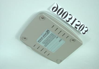
Click to zoom
Application Details
- Equipment Class
- DSS - Part 15 Spread Spectrum Transmitter
- Date of Grant
- Apr 09, 2001
- Application Purpose
- Original Equipment
- Date of Application
- Apr 09, 2001
- Equipment Note
- WLAN USB Adapter
- Frequency Range
- 2412.00000000 - 2462.00000000
- Company
- Delta Electronics, Inc.
- Country
- Taiwan
Documents & Files
Document Text
Text extracted from the exhibit documents filed with the FCC. Open a document above to read the original.
Users Manual
Wireless USB Adapter User Manual Federal Communications Commission (FCC) Compliance Notice: Radio Frequency Notice This device complies with part 15 of the FCC Rules. Operation is subject to the following two conditions: 1. This device may not cause harmful interference. 2. This device must accept any interference received, including interference that may cause undesired operation. Note: This equipment has been tested and found to comply with the limits for a Class B digital device, pursuant to part 15 of the FCC Rules. These limits are designed to provide reasonable protection against harmful interference in a residential installation. This equipment generates, uses, and can radiate radio frequency energy and, if not installed and used in accordance with the instructions, may cause harmful interference to radio communications. However, there is no guarantee that interference will not occur in a particular installation. If this equipment does cause harmful interference to radio or television reception, which can be determined by turning the equipment off and on, the user is encouraged to try to correct the interference by one or more of the following measures: (1) Reorient or relocate the receiving antenna, (2) Increase the separation between the equipment and receiver, (3) Connect the equipment into an outlet on a circuit different from that to which the receiver is connected, (4) Consult the dealer or an experienced radio/TV technician for help. Federal Communications Commission (FCC) Radiation Exposure Statement This equipment complies with FCC radiation exposure limits set forth for an uncontrolled environment. In order to avoid the possibility of exceeding the FCC radio frequency exposure limits, human proximity to the antenna shall not be less than 20 cm (8 inches) during normal operation. Wireless USB Adapter iii TABLE OF CONTENT TABLE OF CONTENT........................................................III INTRODUCTION.................................................................1 CONNECT THE USB ADAPTER TO YOUR DESKTOP PC.....2 HARDWARE INSTALLATION.....................................................2 DRIVER INSTALLATION.....................................................2 INSTALL DRIVER UNDER WINDOWS 98.....................................2 INSTALL DRIVER UNDER WINDOWS ME....................................6 INSTALL DRIVER UNDER WINDOWS 2000..................................9 CONFIGURATION UTILITY..............................................13 I NSTALL THE C ONFIGURATION U TILITY ...................................13 CONFIGURE THE CONFIGURATION UTILITY..............................16 MONITOR....................................................................16 STATISTICS..................................................................18 SITE SURVEY...............................................................19 ENCRYPTION...............................................................20 ADVANCED..................................................................21 VERSION.....................................................................22 Wireless USB Adapter 1 Introduction The Wireless USB Adapter solution overcomes the limitations of wired networks by providing fast, simple, mobile and reliable access. It is designed for desktop computers running Windows 98, 2000 and Millennium. Features ß Complies with the IEEE 802.11b Direct Sequence Spread Spectrum ß Complies with USB specification 1.0 ß Supports 1, 2, 5.5 and 11Mbps Data Rates ß Wired Equivalent Privacy (WEP) 40-bit data encryption ß Provides Firmware upgrade utility via USB port ß Use USB Bus power and no external power supply needed ß Dipole antenna ß Driver Supports Microsoft®Windows®98/2000, Millennium ß FCC Part 15, CE, C-tick, Telec & JATE Wireless USB Adapter 2 Connect the USB Adapter to Your Desktop PC Hardware Installation ß Power on your desktop PC. ß Connect the USB Adapter to the USB port of a desktop PC. ß Insert the driver CD into your CD drive (F:\). ß The Hardware Installation is complete. Driver Installation Install Driver Under Windows 98 1. Connect the Wireless USB adapter into your PC. Windows 98 will automatically recognize a new USB device. Click the Next button to proceed. Wireless USB Adapter 3 2. Select “Search for the best driver for your device” and click the Next button to continue. 3. Make sure that Specify a location is selected and click the Browse button. At this point, Windows will ask you to browse for the folder. Simply select the folder in which the driver is located (F:\) and click the Next button.. Wireless USB Adapter 4 4. Windows is now ready to install the driver. Click the Next button to continue. 5. After Windows copies files from your CD, you will be notified that installation has been completed. Click the Finish button to continue. Wireless USB Adapter 5 6. Windows will now ask you to restart your computer. Click the Yes button to restart your PC. 7. Click right on My computer and select properties. Select Device Manager and click on the Network adapters. You will find the Wireless 802.11 USB Adapter if it is installed successfully. The USB adapter driver installation is finished. You can continue on to Utility Installation. Wireless USB Adapter 6 Install Driver Under Windows ME 1. Windows automatically recognizes a new USB added. Select Specify the location of the driver and click the Next button proceed. 2. At this point, Windows will ask you for new drivers. Make sure Search for the best driver for your device and Specify a location are selected. Click the Browse button, simply select the folder in which the driver is located (F:\) and click the Next button to proceed. Wireless USB Adapter 7 3. Windows is now ready to install the driver. Click the Next button to continue. 4. Windows will notify that installing has been completed. Click the Finish button to continue. Wireless USB Adapter 8 5. Windows will now ask you to restart your computer. Click the Yes button to rest…
Text truncated - open the document above for the full version.
Block Diagram
HFA3683A (2.4GHz RF/IF Converter and Synthesizer) HFA3783 (I/Q Mod/DeMod and Synthesizer) HFA3861B (Baseband Processor) AT76C503A (MAC) HFA3983 (2.4GHz Power Amplifier) ANTENNA USB FLASHSRAM 36MHz OSC 12MHz CRY 44MHz OSC LM-WU110RA
External Photos
Report No.: RF900315031Issued: March 29, 2001 ANNEX 3 PHOTOGRAPHS OF EUT
ID Label/Location Info
FCC ID LABEL LOCATION
Internal Photos
Report No.: RF900315032Issued: March 29, 2001 Report No.: RF900315033Issued: March 29, 2001 Report No.: RF900315034Issued: March 29, 2001
Test Report
FCC ID: PD5LMWU110 Report No.: RF90031503 1 Issued: March 29, 2001 FCC TEST REPORT REPORT NO.: RF90031503 MODEL NO.: LM-WU110 RECEIVED: March 15, 2001 TESTED: March 28, 2001 APPLICANT: Delta Networks, Inc. ADDRESS: No.8, Kon Jan West Road, Liutu Industrial Zone, Keelung, Taiwan, R.O.C. ISSUED BY: Advance Data Technology Corporation LAB LOCATION: 13-1, Lane 19, Wen Shan 3 rd St., Kweishan, Taoyuan Hsien, Taiwan, R.O.C. This test report consists of 48 pages in total. It may be duplicated completely for legal use with the approval of the applicant. It should not be reproduced except in full, without the written approval of our laboratory. The client should not use it to claim product endorsement by NVLAP or any U.S. government agencies. The test results in the report only apply to the tested sample. Accredited Laboratory FCC ID: PD5LMWU110 Report No.: RF90031503 2 Issued: March 29, 2001 Table of Contents 1CERTIFICATION .................................................................................................. 4 2SUMMARY OF TEST RESULTS......................................................................... 5 3GENERAL INFORMATION ................................................................................ 6 3.1GENERAL DESCRIPTION OF EUT ................................................................................ 6 3.2DESCRIPTION OF TEST MODES ................................................................................... 6 3.3GENERAL DESCRIPTION OF APPLIED STANDARDS ............................................... 7 3.4DESCRIPTION OF SUPPORT UNITS.............................................................................. 7 4TEST PROCEDURES AND TEST RESULTS .................................................... 8 4.1CONDUCTED EMISSION MEASUREMENT................................................................. 8 4.1.1LIMITS OF CONDUCTED EMISSION MEASUREMENT ...........................................................8 4.1.2TEST INSTRUMENTS ....................................................................................................................8 4.1.3TEST PROCEDURES ......................................................................................................................9 4.1.4TEST SETUP ..................................................................................................................................10 4.1.5TEST RESULTS .............................................................................................................................11 4.2RADIATED EMISSION MEASUREMENT ................................................................... 17 4.2.1LIMITS OF RADIATED EMISSION MEASUREMENT .............................................................17 4.2.2TEST INSTRUMENTS ..................................................................................................................18 4.2.3TEST PROCEDURES ....................................................................................................................19 4.2.4TEST SETUP ..................................................................................................................................20 4.2.5TEST RESULTS .............................................................................................................................21 4.36dB BANDWIDTH MEASUREMENT ........................................................................... 25 4.3.1LIMITS OF 6 D B BANDWIDTH MEASUREMENT.....................................................................25 4.3.2TEST INSTRUMENTS ..................................................................................................................25 4.3.3TEST PROCEDURE.......................................................................................................................26 4.3.4TEST SETUP ..................................................................................................................................26 4.3.5EUT OPERATING CONDITION...................................................................................................26 4.3.6TEST RESULTS .............................................................................................................................27 4.4MAXIMUM PEAK OUTPUT POWER........................................................................... 31 4.4.1LIMITS OF MAXIMUM PEAK OUTPUT POWER MEASUREMENT......................................31 4.4.2INSTRUMENTS.............................................................................................................................31 4.4.3TEST PROCEDURES ....................................................................................................................32 4.4.4TEST SETUP ..................................................................................................................................32 4.4.5EUT OPERATING CONDITION...................................................................................................32 4.4.6TEST RESULTS .............................................................................................................................33 4.5POWER SPECTRAL DENSITY MEASUREMENT ...................................................... 34 4.5.1LIMITS OF POWER SPECTRAL DENSITY MEASUREMENT ................................................34 4.5.2TEST INSTRUMENTS ..................................................................................................................34 4.5.3TEST PROCEDURE.......................................................................................................................35 FCC ID: PD5LMWU110 Report No.: RF90031503 3 Issued: March 29, 2001 4.5.4TEST SETUP ..................................................................................................................................35 4.5.5EUT OPERATING CONDITION...................................................................................................35 4.5.6TEST RE…
Text truncated - open the document above for the full version.
Test Report
FCC ID: PD5LMWU110 Report No.: RF90031503 1 Issued: March 29, 2001 FCC TEST REPORT REPORT NO.: RF90031503 MODEL NO.: LM-WU110 RECEIVED: March 15, 2001 TESTED: March 28, 2001 APPLICANT: Delta Networks, Inc. ADDRESS: No.8, Kon Jan West Road, Liutu Industrial Zone, Keelung, Taiwan, R.O.C. ISSUED BY: Advance Data Technology Corporation LAB LOCATION: 13-1, Lane 19, Wen Shan 3 rd St., Kweishan, Taoyuan Hsien, Taiwan, R.O.C. This test report consists of 48 pages in total. It may be duplicated completely for legal use with the approval of the applicant. It should not be reproduced except in full, without the written approval of our laboratory. The client should not use it to claim product endorsement by NVLAP or any U.S. government agencies. The test results in the report only apply to the tested sample. Accredited Laboratory FCC ID: PD5LMWU110 Report No.: RF90031503 2 Issued: March 29, 2001 Table of Contents 1CERTIFICATION .................................................................................................. 4 2SUMMARY OF TEST RESULTS......................................................................... 5 3GENERAL INFORMATION ................................................................................ 6 3.1GENERAL DESCRIPTION OF EUT ................................................................................ 6 3.2DESCRIPTION OF TEST MODES ................................................................................... 6 3.3GENERAL DESCRIPTION OF APPLIED STANDARDS ............................................... 7 3.4DESCRIPTION OF SUPPORT UNITS.............................................................................. 7 4TEST PROCEDURES AND TEST RESULTS .................................................... 8 4.1CONDUCTED EMISSION MEASUREMENT................................................................. 8 4.1.1LIMITS OF CONDUCTED EMISSION MEASUREMENT ...........................................................8 4.1.2TEST INSTRUMENTS ....................................................................................................................8 4.1.3TEST PROCEDURES ......................................................................................................................9 4.1.4TEST SETUP ..................................................................................................................................10 4.1.5TEST RESULTS .............................................................................................................................11 4.2RADIATED EMISSION MEASUREMENT ................................................................... 17 4.2.1LIMITS OF RADIATED EMISSION MEASUREMENT .............................................................17 4.2.2TEST INSTRUMENTS ..................................................................................................................18 4.2.3TEST PROCEDURES ....................................................................................................................19 4.2.4TEST SETUP ..................................................................................................................................20 4.2.5TEST RESULTS .............................................................................................................................21 4.36dB BANDWIDTH MEASUREMENT ........................................................................... 25 4.3.1LIMITS OF 6 D B BANDWIDTH MEASUREMENT.....................................................................25 4.3.2TEST INSTRUMENTS ..................................................................................................................25 4.3.3TEST PROCEDURE.......................................................................................................................26 4.3.4TEST SETUP ..................................................................................................................................26 4.3.5EUT OPERATING CONDITION...................................................................................................26 4.3.6TEST RESULTS .............................................................................................................................27 4.4MAXIMUM PEAK OUTPUT POWER........................................................................... 31 4.4.1LIMITS OF MAXIMUM PEAK OUTPUT POWER MEASUREMENT......................................31 4.4.2INSTRUMENTS.............................................................................................................................31 4.4.3TEST PROCEDURES ....................................................................................................................32 4.4.4TEST SETUP ..................................................................................................................................32 4.4.5EUT OPERATING CONDITION...................................................................................................32 4.4.6TEST RESULTS .............................................................................................................................33 4.5POWER SPECTRAL DENSITY MEASUREMENT ...................................................... 34 4.5.1LIMITS OF POWER SPECTRAL DENSITY MEASUREMENT ................................................34 4.5.2TEST INSTRUMENTS ..................................................................................................................34 4.5.3TEST PROCEDURE.......................................................................................................................35 FCC ID: PD5LMWU110 Report No.: RF90031503 3 Issued: March 29, 2001 4.5.4TEST SETUP ..................................................................................................................................35 4.5.5EUT OPERATING CONDITION...................................................................................................35 4.5.6TEST RE…
Text truncated - open the document above for the full version.
Test Report
FCC ID: PD5LMWU110 Report No.: RF90031503 1 Issued: March 29, 2001 ANNEX 1 PROCESSING GAIN OF DIRECT SEQUENCE SPREAD SPECTRUM MEASUREMENT 1. 1.1. 1. LIMITS OF PROCESSING GAIN OF A DIRECT SEQUENCE SPREAD SPECTRUM MEASUREMENT The limit of processing gain is 10dB 1.1 TEST INSTRUMENTS & SUPPORT UNIT Description & ManufacturerModel No.Serial No. Anritsu Spectrum Analyzer, 9kHz to 30GHz MS2667CM10281 Anritsu Signal Generator, 10kHz to 20GHz 68247B984703 Hewlett Packard Power Meter,HP438A2743A04416 Hewlett Packard Power Sensor, -30 to 20dBm 8485A2942A08387 Hewlett Packard Step Attenuator, 10dB steps HP8496B3247A18505 Mini-Circuits Power SplitterZN2PD-9GNA DELL Laptop ComputerInspiron 5000eNA Campaq Laptop ComputerPPX99125 FCC ID: PD5LMWU110 Report No.: RF90031503 2 Issued: March 29, 2001 1.2 METHOD OF MEASUREMENT The processing gain may be measured using the CW jamming margin method. Section 4.7.4 shows the test configuration. The test consists of stepping a signal generator in 50 kHz increments across the passband of the system. At each point, the generator level required to produce the recommended Bit Error Rate (BER) is recorded. This level is jammer level. The output power of the transmitting unit is measured at the same point. The jammer to Signal (J/S) ratio is then calculated. Discard the worst 20% of the J/S data points. The lowest remaining J/S ratio is used when calculating the Process Gain. The reference PER is specified as 8%. The corresponding Es/No (signal to noise ratio per symbol) is 16.4 dB. The curve is attached as below. This value and the measured J/S ratio are used in the following equation to calculate the Process Gain (Gp) of the system. Where: (S/N) o : Signal to noise ratio for the chosen BER. Gp = (S/N) o +Mj+Lsys FCC ID: PD5LMWU110 Report No.: RF90031503 3 Issued: March 29, 2001 Mj : Maximum jammer to Signal Ratio recorded at the detected BER. Lsys : System losses . For the purpose of this processing gain calculation, we assume Lsys at its minimum value of 2 dB. TEST SETUP 7 NOTEBOOK EUT ANRITSU SIGNAL GENERATOR EUT NOTEBOOK PWR SENSOR 8485A Power meter HP 438A Mini-Circuits 15542 ZNZPD-9G HP8496D STEP ATTN 110dB (10dB steps) Matched Cables RECEIVER Transmitter FCC ID: PD5LMWU110 Report No.: RF90031503 4 Issued: March 29, 2001 1.3 TEST PROCEDURES Obtain the simplex link shown. Perform all independent instrumentation calibrations prior to this procedure. Set operating power levels using fixed and variable attenuators in system to meet the following objectives: Signal Power at receiver approximately –55dBm (above thermal sensitivity such that thermal noise does not cause bit errors. Signal Power at power meter between –20 and –30dBm for optimal linearity. Use spectrum analyzer to monitor test. Ensure that CW Jammer generator RF output is disabled and measure the power at the power meter port using the power meter. This is the relative signal power, Sr. Disable Transmitter, and set CW Jammer generator RF output frequency equal to the carrier frequency and enable generator output. Set reference CW Jammer power level at power meter port 8.4dB below Sr (minimum J/S, or 10dB processing gain reference level). Note the power level setting on the generator, this is the reference CW Jammer power setting, Jr. Disable CW Jammer, re-establish link. PER test should be operating essentially error -free. Enable CW Jammer at the reference power level and verify that the PER test indicates a PER of less than 8%. Alternatively, adjust the CW Jammer level to that which causes 8% PER and verify that the S/J is less than 8.4dB. Repeat step 7 for uniform steps in frequency increments of 50 kHz across the receiver passband with the CW Jammer. In this case the receiver passband is +/- 8.5 MHz. The numerical data associated with the following radio channel is tabulated and presented for Channel 1,6, and 11. Note:Since the jamming signal will be blocked by the IF filter if the jamming frequency is far form the center of the carrier frequency. So, only those frequencies around carrier frequency are shown here. FCC ID: PD5LMWU110 Report No.: RF90031503 5 Issued: March 29, 2001 1.4 EUT OPERATING CONDITION The software provided by client to set the EUT to transmit at lowest, middle and highest channel. 1.5 TEST RESULTS EUTWireless Access PointModelLM-WS120 Environmental Conditions24°C, 70%RHTe s t e d B ySteven Lu Although the theoretical processing gain is lower than 10 dB, but the CCK coding provides an extra coding gain of 2.2dB. 11Mbps CHANNEL 1 Processing Gain FrequencyGp(S/N)Mj = J/SLsys (GHz)(dB)(dB)(dB)(dB) 2.40800 13.4 16.4 -5.0 2 2.40805 13.6 16.4 -4.8 2 2.40810 13.3 16.4 -5.1 2 2.40815 13.3 16.4 -5.1 2 2.40820 13.4 16.4 -5.0 2 2.40825 13.4 16.4 -5.0 2 2.40830 13.0 16.4 -5.4 2 2.40835 13.2 16.4 -5.2 2 2.40840 12.7 16.4 -5.7 2 2.40845 12.5 16.4 -5.9 2 2.40850 12.7 16.4 -5.7 2 2.40855 12.8 16.4 -5.6 2 2.40860 12.5 16.4 -5.9 2 2.40865 12.7 16.4 -5.7 2 2.40870 12.3 16.4 -6.1 2 2.40875 12.6 16.4 -5.8 2 2.40880 12.5 16.4 -5.9 2 2.40885 12.7 16.4 -5.6 2 2.40890 12.2 16.4 -6.2 2 2.40895 12.0 16.4 -6.4 2 FCC ID: PD5LMWU110 Report No.: RF90031503 6 Issued: March 29, 2001 11Mbps CHANNEL 1 Processing Gain FrequencyGp(S/N)Mj = J/SLsys (GHz)(dB)(dB)(dB)(dB) 2.40900 12.0 16.4 -6.4 2 2.40950 11.8 16.4 -6.6 2 2.40955 11.9 16.4 -6.5 2 2.40960 11.6 16.4 -6.8 2 2.40965 11.8 16.4 -6.6 2 2.40970 11.4 16.4 -7.0 2 2.40975 11.6 16.4 -6.8 2 2.40980 11.6 16.4 -6.8 2 2.40985 11.3 16.4 -7.1 2 2.40990 11.4 16.4 -7.0 2 2.40995 11.3 16.4 -7.1 2 2.41000 11.4 16.4 -7.0 2 2.41005 11.2 16.4 -7.2 2 2.41010 11.4 16.4 -7.0 2 2.41015 11.2 16.4 -7.2 2 2.41020 11.3 16.4 -7.1 2 2.41025 11.6 16.4 -6.8 2 2.41030 11.8 16.4 -6.6 2 2.41035 11.6 16.4 -6.8 2 2.41040 11.7 16.4 -6.7 2 2.41045 11.4 16.4 -7.0 2 2.41050 11.4 16.4 -7.0 2 2.41055 11.5 16.4 -6.9 2 2.41060 11.4 16.4 -7.0 2 2.41065 11.7 16.4 -6.7 2 2.41070 11.4 16.4 -7.0 2 2.41075 11.6 16.4 -6.8 2 2.41080 11.9 16.4 -6.5 2 2.41085 11.7 16.4 -6.7 2 2.41090 12.0 16.4 -6.4 2 2.41095 11…
Text truncated - open the document above for the full version.
Test Report
FCC ID: PD5LMWU110 Report No.: RF900315031Issued: March 29, 2001 ANNEX 2 DSSS INFORMATION This device is Direct Sequence Spread Spectrum, the data is mixed by pseudorandom code which is an orthogonal code. The mixed data is digital modulated by BPSK and QPSK technique depends on the data rates. The CCK coding is applied for increasing the data rate, and also the processing gain will be increased. The bit rates are 1,2,5.5,11Mbps, the symbol rates are 1,1,1.375,1.375Mbps, the chip rates are always 11Mbps. So, the Chip/symbol is 11,11,8 and 8 respectively. Although is higher bit rate, the processing gain is lower than 10, but the CCK coding used in higher bit rate will provide 2.2dB coding gain.
Test Setup Photos
FCC ID: PD5LMWU110 Report No.: RF90031503 46 Issued: March 29, 2001 5 PHOTOGRAPHS OF THE TEST CONFIGURATION CONDUCTED EMISSION TEST FCC ID: PD5LMWU110 Report No.: RF90031503 47 Issued: March 29, 2001 RADIATED EMISSION TEST
Contact Information
Applicant
Payton Ting(Manager)
Test Firm
Bureau Veritas CPS (H.K.) Ltd. Taoyuan BranchTommy Wu
Technical Specifications
| # | Rule Parts | Frequency Range | Power Output |
|---|---|---|---|
| 1 | 15C | 2.41 GHz - 2.46 GHz | 53.00 mW |
Other Applications from Delta Electronics, Inc.
PD5-NWA1200
Jun 16, 2026Indoor Wireless AP
Equipment Class
DTS - Digital Transmission SystemPD5-AP743
Jun 03, 2026802.11be enterprise access point
Equipment Class
NII - Unlicensed National Information Infrastructure TXPD5-AP623E
Sep 04, 2025802.11ax enterprise access point
Equipment Class
NII - Unlicensed National Information Infrastructure TX
PD5-LM-WESA04OR
Aug 01, 2021802.11 b/g/n/ac WIFI AP
Equipment Class
NII - Unlicensed National Information Infrastructure TX
PD5-NWA1000
Jul 25, 2021Wireless Access Point
Equipment Class
NII - Unlicensed National Information Infrastructure TX