PD5TQ2403Enterprise Wlan AP
Delta Electronics, Inc.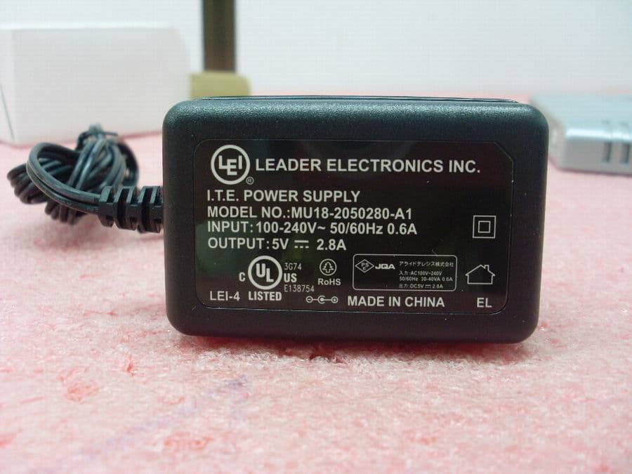
Click to zoom
Application Details
- Equipment Class
- NII - Unlicensed National Information Infrastructure TX
- Date of Grant
- Apr 04, 2010
- Application Purpose
- Original Equipment
- Date of Application
- Jun 06, 2009
- Equipment Note
- Enterprise Wlan AP
- Frequency Range
- 5500.00000000 - 5560.00000000
- Company
- Delta Electronics, Inc.
- Country
- Taiwan
Documents & Files
Document Text
Text extracted from the exhibit documents filed with the FCC. Open a document above to read the original.
Users Manual
PN 613-0011579 Rev. A AT-TQ2403 IEEE 802.11abgh, Dual Radio, Enterprise Wireless Access Point Installation Guide PN 613-0011579 Rev. A AT-TQ2403 IEEE 802.11abgh, Dual Radio, Enterprise Wireless Access Point Installation Guide 2 AT-TQ2403 - IEEE 802.11abgh, Dual Radio, Enterprise Wireless Access Point - Installation Guide Copyright © 2009 Allied Telesis, Inc. All rights reserved. No part of this publication may be reproduced without prior written permission from Allied Telesis, Inc. Microsoft and Internet Explorer are registered trademarks of Microsoft Corporation. Netscape Navigator is a registered trademark of Netscape Communications Corporation. All other product names, company names, logos or other designations mentioned herein are trademarks or registered trademarks of their respective owners. Allied Telesis, Inc. reserves the right to make changes in specifications and other information contained in this document without prior written notice. The information provided herein is subject to change without notice. In no event shall Allied Telesis, Inc. be liable for any incidental, special, indirect, or consequential damages whatsoever, including but not limited to lost profits, arising out of or related to this manual or the information contained herein, even if Allied Telesis, Inc. has been advised of, known, or should have known, the possibility of such damages. AT-TQ2403 IEEE 802.11abgh, Dual Radio, Enterprise Wireless Access Point Installation Guide 3 SAFETY NOTICE 9 Do not open service or change any component. 9 Only qualified technicians are allowed to service the equipment. 9 Observe safety precautions to avoid electric shock 9 Check voltage before connecting to the power supply. Connecting to the wrong voltage will damage the equipment. LIMITATION OF LIABILITY AND DAMAGES THE PRODUCT AND THE SOFTWARES WITHIN ARE PROVIDED "AS IS," BASIS. THE MANUFACTURER AND MANUFACTURER’S RESELLERS (COLLECTIVELY REFERRED TO AS “THE SELLERS”) DISCLAIM ALL WARRANTIES, EXPRESS, IMPLIED OR STATUTORY, INCLUDING WITHOUT LIMITATION THE IMPLIED WARRANTIES OF NON-INFRINGEMENT, MERCHANTABILITY OR FITNESS FOR A PARTICULAR PURPOSE, OR ANY WARRANTIES ARISING FROM COURSE OF DEALING, COURSE OF PERFORMANCE, OR USAGE OF TRADE. IN NO EVENT WILL THE SELLERS BE LIABLE FOR DAMAGES OR LOSS, INCLUDING BUT NOT LIMITED TO DIRECT, INDIRECT, SPECIAL WILFUL, PUNITIVE, INCIDENTAL, EXEMPLARY, OR CONSEQUENTIAL, DAMAGES, DAMAGES FOR LOSS OF BUSINESS PROFITS, OR DAMAGES FOR LOSS OF BUSINESS OF ANY CUSTOMER OR ANY THIRD PARTY ARISING OUT OF THE USE OR THE INABILITY TO USE THE PRODUCT OR THE SOFTWARES, INCLUDING BUT NOT LIMITED TO THOSE RESULTING FROM DEFECTS IN THE PRODUCT OR SOFTWARE OR DOCUMENTATION, OR LOSS OR INACCURACY OF DATA OF ANY KIND, WHETHER BASED ON CONTRACT, TORT OR ANY OTHER LEGAL THEORY, EVEN IF THE PARTIES HAVE BEEN ADVISED OF THE POSSIBILITY OF SUCH DAMAGES. THE ENTIRE RISK AS TO THE RESULTS AND PERFORMANCE OF THE PRODUCT OR ITS SOFTWARE IS ASSUMED BY CUSTOMER. BECAUSE SOME STATES DO NOT ALLOW THE EXCLUSION OR LIMITATION OF LIABILITY FOR DAMAGES, THE ABOVE LIMITATION MAY NOT APPLY TO THE PARTIES. IN NO EVENT WILL THE SELLERS’ TOTAL CUMULATIVE LIABILITY OF EACH AND EVERY KIND IN RELATION TO THE PRODUCT OR ITS SOFTWARE EXCEED THE AMOUNT PAID BY CUSTOMER FOR THE PRODUCT. 4 AT-TQ2403 - IEEE 802.11abgh, Dual Radio, Enterprise Wireless Access Point - Installation Guide ELECTRICAL SAFETY AND EMISSIONS STANDARDS This product meets the following standards. U.S. Federal Communications Commission Interference Statement This equipment has been tested and found to comply with the limits for a Class B digital device, pursuant to Part 15 of the FCC Rules. These limits are designed to provide reasonable protection against harmful interference in a residential installation. This equipment generates, uses and can radiate radio frequency energy and, if not installed and used in accordance with the instructions, may cause harmful interference to radio communications. However, there is no guarantee that interference will not occur in a particular installation. If this equipment does cause harmful interference to radio or television reception, which can be determined by turning the equipment off and on, the user is encouraged to try to correct the interference by one of the following measures: - Reorient or relocate the receiving antenna. - Increase the separation between the equipment and receiver. - Connect the equipment into an outlet on a circuit different from that to which the receiver is connected. - Consult the dealer or an experienced radio/TV technician for help. FCC Caution: Any changes or modifications not expressly approved by the party responsible for compliance could void the user's authority to operate this equipment. For operation within 5.15 ~ 5.25GHz frequency range, it is restricted to indoor environment. This device complies with Part 15 of the FCC Rules. Operation is subject to the following two conditions: (1) This device may not cause harmful interference, and (2) this device must accept any interference received, including interference that may cause undesired operation. Radiation Exposure Statement: This equipment complies with FCC radiation exposure limits set forth for an uncontrolled environment. This equipment should be installed and operated with minimum distance 20cm between the radiator & your body. This transmitter must not be co-located or operating in conjunction with any other antenna or transmitter. The availability of some specific channels and/or operational frequency bands are country dependent and are firmware programmed at the factory to match the intended destination. The firmware setting is not accessible by the end user. Canadian Department of Communications This device complies with RSS-210 of the Industry Canada Rules. Operation is subject to the following two conditions: (1) This device may not cause harmful interference, and (2) this device must accept any interference received, incl…
Text truncated - open the document above for the full version.
Users Manual
PN 613-00157 Rev. B AT-TQ2403 IEEE 802.11abgh, Dual Radio, Enterprise Wireless Access Point Installation Guide 2 AT-TQ2403 - IEEE 802.11abgh, Dual Radio, Enterprise Wireless Access Point - Installation Guide Copyright © 2009 Allied Telesis, Inc. All rights reserved. No part of this publication may be reproduced without prior written permission from Allied Telesis, Inc. Microsoft and Internet Explorer are registered trademarks of Microsoft Corporation. Netscape Navigator is a registered trademark of Netscape Communications Corporation. All other product names, company names, logos or other designations mentioned herein are trademarks or registered trademarks of their respective owners. Allied Telesis, Inc. reserves the right to make changes in specifications and other information contained in this document without prior written notice. The information provided herein is subject to change without notice. In no event shall Allied Telesis, Inc. be liable for any incidental, special, indirect, or consequential damages whatsoever, including but not limited to lost profits, arising out of or related to this manual or the information contained herein, even if Allied Telesis, Inc. has been advised of, known, or should have known, the possibility of such damages. AT-TQ2403 IEEE 802.11abgh, Dual Radio, Enterprise Wireless Access Point Installation Guide 3 SAFETY NOTICE 9 Do not open service or change any component. 9 Only qualified technicians are allowed to service the equipment. 9 Observe safety precautions to avoid electric shock 9 Check voltage before connecting to the power supply. Connecting to the wrong voltage will damage the equipment. LIMITATION OF LIABILITY AND DAMAGES THE PRODUCT AND THE SOFTWARES WITHIN ARE PROVIDED "AS IS," BASIS. THE MANUFACTURER AND MANUFACTURER’S RESELLERS (COLLECTIVELY REFERRED TO AS “THE SELLERS”) DISCLAIM ALL WARRANTIES, EXPRESS, IMPLIED OR STATUTORY, INCLUDING WITHOUT LIMITATION THE IMPLIED WARRANTIES OF NON-INFRINGEMENT, MERCHANTABILITY OR FITNESS FOR A PARTICULAR PURPOSE, OR ANY WARRANTIES ARISING FROM COURSE OF DEALING, COURSE OF PERFORMANCE, OR USAGE OF TRADE. IN NO EVENT WILL THE SELLERS BE LIABLE FOR DAMAGES OR LOSS, INCLUDING BUT NOT LIMITED TO DIRECT, INDIRECT, SPECIAL WILFUL, PUNITIVE, INCIDENTAL, EXEMPLARY, OR CONSEQUENTIAL, DAMAGES, DAMAGES FOR LOSS OF BUSINESS PROFITS, OR DAMAGES FOR LOSS OF BUSINESS OF ANY CUSTOMER OR ANY THIRD PARTY ARISING OUT OF THE USE OR THE INABILITY TO USE THE PRODUCT OR THE SOFTWARES, INCLUDING BUT NOT LIMITED TO THOSE RESULTING FROM DEFECTS IN THE PRODUCT OR SOFTWARE OR DOCUMENTATION, OR LOSS OR INACCURACY OF DATA OF ANY KIND, WHETHER BASED ON CONTRACT, TORT OR ANY OTHER LEGAL THEORY, EVEN IF THE PARTIES HAVE BEEN ADVISED OF THE POSSIBILITY OF SUCH DAMAGES. THE ENTIRE RISK AS TO THE RESULTS AND PERFORMANCE OF THE PRODUCT OR ITS SOFTWARE IS ASSUMED BY CUSTOMER. BECAUSE SOME STATES DO NOT ALLOW THE EXCLUSION OR LIMITATION OF LIABILITY FOR DAMAGES, THE ABOVE LIMITATION MAY NOT APPLY TO THE PARTIES. IN NO EVENT WILL THE SELLERS’ TOTAL CUMULATIVE LIABILITY OF EACH AND EVERY KIND IN RELATION TO THE PRODUCT OR ITS SOFTWARE EXCEED THE AMOUNT PAID BY CUSTOMER FOR THE PRODUCT. 4 AT-TQ2403 - IEEE 802.11abgh, Dual Radio, Enterprise Wireless Access Point - Installation Guide ELECTRICAL SAFETY AND EMISSIONS STANDARDS This product meets the following standards. U.S. Federal Communications Commission Interference Statement This equipment has been tested and found to comply with the limits for a Class B digital device, pursuant to Part 15 of the FCC Rules. These limits are designed to provide reasonable protection against harmful interference in a residential installation. This equipment generates, uses and can radiate radio frequency energy and, if not installed and used in accordance with the instructions, may cause harmful interference to radio communications. However, there is no guarantee that interference will not occur in a particular installation. If this equipment does cause harmful interference to radio or television reception, which can be determined by turning the equipment off and on, the user is encouraged to try to correct the interference by one of the following measures: - Reorient or relocate the receiving antenna. - Increase the separation between the equipment and receiver. - Connect the equipment into an outlet on a circuit different from that to which the receiver is connected. - Consult the dealer or an experienced radio/TV technician for help. FCC Caution: Any changes or modifications not expressly approved by the party responsible for compliance could void the user's authority to operate this equipment. For operation within 5.15 ~ 5.25GHz frequency range, it is restricted to indoor environment. This device complies with Part 15 of the FCC Rules. Operation is subject to the following two conditions: (1) This device may not cause harmful interference, and (2) this device must accept any interference received, including interference that may cause undesired operation. Radiation Exposure Statement: This equipment complies with FCC radiation exposure limits set forth for an uncontrolled environment. This equipment should be installed and operated with minimum distance 20cm between the radiator & your body. This transmitter must not be co-located or operating in conjunction with any other antenna or transmitter. The availability of some specific channels and/or operational frequency bands are country dependent and are firmware programmed at the factory to match the intended destination. The firmware setting is not accessible by the end user. FCC Caution: This equipment complies with Part 15E of the FCC Rules with radar detection function and DFS capability. Operation is subject to the following three conditions: (1) This device is intended to use indoor operations only. (2) This device will not permit operations on channels which overlap the 5600 - 5650 MHz band. (3) This device meets all the other requirements specified…
Text truncated - open the document above for the full version.
Cover Letter(s)
香港商立 Bureau Ve r i t a s Consumer Products Services (H.K.) Ltd., Taoyuan Branch 香港商立德國際商品試驗有限公司桃園分公司 No.19,Hwa Ya 2 nd Rd,Kwei Shan Hsiang ,taoyuan Hsien ,Taiwan, R.O.C. 桃園縣龜山鄉華亞二路19號 http://www.adt.com.tw/ E-mail: [email protected] TEL: 886-3-3183232 FAX: 886-3-3270892 Mar,02 2010 Supersede request for FCC ID: PD5TQ2403 To Whom It May Concern: We regret to inform you that due to client request, we need to change the external photo. Since the label of power adapter has been modified. Original Modified So we would like to request the FCC to supersede the exhibit described as “External photos” outlined below with red color. Sincerely yours, Gary Chang Assistant Manager Bureau Veritas Consumer Products Services (H.K.) Ltd., Taoyuan Branch Tel: 886-3-3183232 ext. 1608 Fax: 886-3-3270892 Email: Gary_chang@ adt.com.tw
External Photos
Page 1 CONSTRUCTION PHOTOS OF EUT Page 2 Page 3 Page 4
ID Label/Location Info
FCC ID .: PD5TQ2403 Label Location
ID Label/Location Info
Model: AT-TQ2403 P/N:990-002814 E183341 FCC ID: PD5TQ2403 IC: 3970A-ATTQ2403 SPECIFIC STANDARDS
Internal Photos
Page 5 Page 6 Page 7 Page 8
Operational Description
FCC ID: PD5TQ2403 Report No.: RF980320L04 Operational Description This device is an Enterprise Wlan AP which operates in the 2.4GHz and 5GHz frequency spectrum with throughput of up to 108Mbps which OFDM technique will be applied. If the signal to noise radio is too poor which could not support 108Mbps, the 11Mbps data rate with DSSS technique will be applied. The transmitter of the EUT is powered by adapter or POE. The antenna is dipole antenna with R-SMA antenna connector. The other instruction, please have a look at the users manual. FCC 15.407(c) states: The device shall automatically discontinue transmission in case of either absence of information to transmit or operational failure. These provisions are not intended to preclude the transmission of control or signaling information or the use of repetitive codes used by certain digital technologies to complete frame or burst intervals. Applicants shall include in their application for equipment authorization a description of how this requirement is met” Data transmission is always initiated by software, which is then pass down through the MAC, through the digital and analog baseband, and finally to the RF chip. Several special packets (ACKs, CTS, PSPoll, etc...) are initiated by the MAC. There are the only ways the digital baseband portion will turn on the RF transmitter, which it then turns off at the end of the packet. Therefore, the transmitter will be on only while one of the aforementioned packets are being transmitted.
RF Exposure Info
FCC ID: PD5TQ2403 Report No.: SA980320L04 Report Format Version 3.0.0 1 RF EXPOSURE REPORT REPORT NO.: SA980320L04 MODEL NO.: AT-TQ2403 ACCORDING: FCC Guidelines for Human Exposure IEEE C95.1 APPLICANT: Delta Networks, Inc. ADDRESS: 252, Shang Ying Road, Kuei San, Taoyuan Shien 333, Taiwan, R.O.C. ISSUED BY: Bureau Veritas Consumer Products Services (H.K.) Ltd., Taoyuan Branch LAB ADDRESS: No. 47, 14th Ling, Chia Pau Tsuen, Lin Kou Hsiang, Taipei Hsien 244, Taiwan, R.O.C. TEST LOCATION: No. 19, Hwa Ya 2nd Rd, Wen Hwa Tsuen, Kwei Shan Hsiang, Taoyuan Hsien 333, Taiwan, R.O.C. FCC ID: PD5TQ2403 Report No.: SA980320L04 Report Format Version 3.0.0 2 RF EXPOSURE MEASUREMENT (MOBILE DEVICE) 1. INTRODUCTION In this document, we try to prove the safety of radiation harmfulness to the human body for our product. The limit for Maximum Permissible Exposure (MPE) specified in FCC 1.1310 is followed. The Gain of the antenna used in this product is measured in a Fully Anechoic Chamber (FAC) calibrated for antenna measurement in ADT, and also the maximum total power input to the antenna is measured. Through the Friis transmission formula and the maximum gain of the antenna, we can calculate the distance, away from the product, where the limit of MPE is reached. Although the Friis transmission formula is a far field assumption, the calculated result of that is an over-prediction for near field power density. We will take that as the worst case to specify the safety range. 2. RF EXPOSURE LIMIT According to FCC 1.1310: The criteria listed in the following table shall be used to evaluate the environmental impact of human exposure to radio-frequency (RF) radiation as specified in 1.1307(b) LIMITS FOR MAXIMUM PERMISSIBLE EXPOSURE (MPE) FREQUENCY RANGE (MHz) ELECTRIC FIELD STRENGTH (V/m) MAGNETIC FIELD STRENGTH (A/m) POWER DENSITY (mW/cm 2 ) AVERAGE TIME (minutes) (A)LIMITS FOR OCCUPATIONAL / CONTROL EXPOSURES 300-1500 ... ... F/300 6 1500-100,000 ... ... 5 6 (B)LIMITS FOR GENERAL POPULATION / UNCONTROLLED EXPOSURE 300-1500 ... ... F/1500 30 1500-100,000 ... ... 1.0 30 F = Frequency in MHz FCC ID: PD5TQ2403 Report No.: SA980320L04 Report Format Version 3.0.0 3 3. FRIIS FORMULA Friis transmission formula : Pd = (Pout*G) / (4*pi*r 2 ) where Pd = power density in mW/cm 2 Pout = output power to antenna in mW G = gain of antenna in linear scale Pi = 3.1416 R = distance between observation point and center of the radiator in cm If we know the maximum Gain of the antenna and the total power input to the antenna, through the calculation, we will know the MPE value at distance r. Ref.: David K. Cheng, Field and Wave Electromagnetics, Second Edition, Page 640, Eq. (11-133). 4. EUT OPERATING CONDITION The software provided by Manufacturer enabled the EUT to transmit and receive data at lowest, middle and highest channel individually. 5. CLASSIFICATION The antenna of this product, under normal use condition, is at least 20cm away from the body of the user. Warning statement to the user for keeping at least 20cm or more separation distance with the antenna should be included in users manual. So, this device is classified as Mobile Device. FCC ID: PD5TQ2403 Report No.: SA980320L04 Report Format Version 3.0.0 4 6. TEST RESULTS 6.1 ANTENNA GAIN The maximum Gain measured in Fully Anechoic Chamber is 2.43dBi or 1.749847(numeric), 2.26dBi or 1.682674(numeric). 6.2 OUTPUT POWER INTO ANTENNA & RF EXPOSURE VALUE AT DISTANCE 20cm: For 2.412 ~ 2.4362GHz band: FOR ANTENNA 2.43dBi GAIN 802.11b DSSS MODULATION CHANNEL CHANNEL FREQUENCY (MHz) PEAK POWER OUTPUT (dBm) PEAK POWER (mW) POWER DENSITY (mW/cm 2 ) LIMIT OF POWER DENSITY (mW/cm 2 ) 1 2412 19.06 80.538 0.028 1.0 6 2437 19.08 80.910 0.028 1.0 11 2462 19.05 80.353 0.028 1.0 802.11g OFDM MODULATION CHANNEL CHANNEL FREQUENCY (MHz) PEAK POWER OUTPUT (dBm) PEAK POWER (mW) POWER DENSITY (mW/cm 2 ) LIMIT OF POWER DENSITY (mW/cm 2 ) 1 2412 21.06 127.644 0.044 1.0 6 2437 23.52 224.905 0.078 1.0 11 2462 21.05 127.350 0.044 1.0 802.11g OFDM MODULATION (TURBO MODE) CHANNEL CHANNEL FREQUENCY (MHz) PEAK POWER OUTPUT (dBm) PEAK POWER (mW) POWER DENSITY (mW/cm 2 ) LIMIT OF POWER DENSITY (mW/cm 2 ) 6 2437 23.02 200.447 0.070 1.0 FCC ID: PD5TQ2403 Report No.: SA980320L04 Report Format Version 3.0.0 5 For 5.180 ~ 5.320GHz & 5.500 ~ 5.700GHz band: FOR ANTENNA 2.26dBi GAIN 802.11a OFDM MODULATION CHANNEL CHANNEL FREQUENCY (MHz) PEAK POWER OUTPUT (dBm) PEAK POWER (mW) POWER DENSITY (mW/cm 2 ) LIMIT OF POWER DENSITY (mW/cm 2 ) 36 5180 15.52 35.645 0.012 1.0 40 5200 16.08 40.551 0.014 1.0 48 5240 16.04 40.179 0.013 1.0 52 5260 16.05 40.272 0.013 1.0 60 5300 16.09 40.644 0.014 1.0 64 5320 16.53 44.978 0.015 1.0 100 5500 16.06 40.365 0.014 1.0 120 5600 16.03 40.087 0.013 1.0 140 5700 16.04 40.179 0.013 1.0 802.11a OFDM MODULATION (TURBO MODE) CHANNEL CHANNEL FREQUENCY (MHz) PEAK POWER OUTPUT (dBm) PEAK POWER (mW) POWER DENSITY (mW/cm 2 ) LIMIT OF POWER DENSITY (mW/cm 2 ) 42 5210 16.04 40.179 0.013 1.0 FCC ID: PD5TQ2403 Report No.: SA980320L04 Report Format Version 3.0.0 6 For 5.745 ~ 5.825GHz band FOR ANTENNA 2.26dBi GAIN 802.11a OFDM MODULATION CHANNEL CHANNEL FREQUENCY (MHz) PEAK POWER OUTPUT (dBm) PEAK POWER (mW) POWER DENSITY (mW/cm 2 ) LIMIT OF POWER DENSITY (mW/cm 2 ) 149 5745 20.02 100.462 0.034 1.0 157 5785 20.09 102.094 0.034 1.0 165 5825 20.04 100.925 0.034 1.0 802.11a OFDM MODULATION (TURBO MODE) CHANNEL CHANNEL FREQUENCY (MHz) PEAK POWER OUTPUT (dBm) PEAK POWER (mW) POWER DENSITY (mW/cm 2 ) LIMIT OF POWER DENSITY (mW/cm 2 ) 152 5760 20.10 102.329 0.034 1.0 160 5800 20.06 101.391 0.034 1.0 CONCULSION: EUT can transmit 2.4 and 5GHz simultaneously through the same antenna, the formula of calculated the MPE is: CPD1 / LPD1 + CPD2 / LPD2 + ......etc. < 1 CPD = Calculation power density LPD = Limit of power density WLAN 2.4G + WLAN 5G = 0.078 + 0.034 = 0.112 Therefore, the maximum calculation of this situation is 0.112, which is less than the “1” limit.
Test Report
Report No.: RF980320L04-1 1 Report Format Version 3.0.0 FCC TEST REPORT (15.407) REPORT NO.: RF980320L04-1 MODEL NO.: AT-TQ2403 RECEIVED: Mar. 19, 2009 TESTED: Apr. 06 ~ Apr. 16, 2009 ISSUED: May 07, 2009 APPLICANT: Delta Networks, Inc. ADDRESS: 252, Shang Ying Road, Kuei San, Taoyuan Shien 333, Taiwan, R.O.C. ISSUED BY: Bureau Veritas Consumer Products Services (H.K.) Ltd., Taoyuan Branch LAB ADDRESS: No. 47, 14th Ling, Chia Pau Tsuen, Lin Kou Hsiang, Taipei Hsien 244, Taiwan, R.O.C. TEST LOCATION: No. 19, Hwa Ya 2nd Rd, Wen Hwa Tsuen, Kwei Shan Hsiang, Taoyuan Hsien 333, Taiwan, R.O.C. This test report consists of 99 pages in total. It may be duplicated completely for legal use with the approval of the applicant. It should not be reproduced except in full, without the written approval of our laboratory. The client should not use it to claim product endorsement by TAF or any government agencies. The test results in the report only apply to the tested sample. Report No.: RF980320L04-1 2 Report Format Version 3.0.0 Table of Contents 1. CERTIFICATION........................................................................................................... 4 2. SUMMARY OF TEST RESULTS .................................................................................. 5 2.1 MEASUREMENT UNCERTAINTY................................................................................ 5 3. GENERAL INFORMATION ........................................................................................... 6 3.1 GENERAL DESCRIPTION OF EUT ............................................................................. 6 3.2 DESCRIPTION OF TEST MODES ............................................................................... 8 3.2.1 CONFIGURATION OF SYSTEM UNDER TEST .......................................................... 9 3.2.2 TEST MODE APPLICABILITY AND TESTED CHANNEL DETAIL ............................. 10 3.3 GENERAL DESCRIPTION OF APPLIED STANDARDS ............................................ 12 3.4 DESCRIPTION OF SUPPORT UNITS ....................................................................... 12 4. TEST TYPES AND RESULTS .................................................................................... 13 4.1 RADIATED EMISSION MEASUREMENT .................................................................. 13 4.1.1 LIMITS OF RADIATED EMISSION MEASUREMENT................................................ 13 4.1.2 LIMITS OF UNWANTED EMISSION OUT OF THE RESTRICTED BANDS .............. 13 4.1.3 TEST INSTRUMENTS................................................................................................ 14 4.1.4 TEST PROCEDURES ................................................................................................ 15 4.1.5 DEVIATION FROM TEST STANDARD....................................................................... 15 4.1.6 TEST SETUP.............................................................................................................. 16 4.1.7 EUT OPERATING CONDITION.................................................................................. 16 4.1.8 TEST RESULTS ......................................................................................................... 17 4.2 CONDUCTED EMISSION MEASUREMENT ............................................................. 33 4.2.1 LIMITS OF CONDUCTED EMISSION MEASUREMENT........................................... 33 4.2.2 TEST INSTRUMENTS................................................................................................ 33 4.2.3 TEST PROCEDURES ................................................................................................ 34 4.2.4 DEVIATION FROM TEST STANDARD....................................................................... 34 4.2.5 TEST SETUP.............................................................................................................. 35 4.2.6 EUT OPERATING CONDITIONS ............................................................................... 35 4.2.7 TEST RESULTS ......................................................................................................... 36 4.3 MAXIMUM CONDUCTED OUTPUT POWER MEASUREMENT ............................... 48 4.3.1 LIMITS OF MAXIMUM CONDUCTED OUTPUT POWER MEASUREMENT............. 48 4.3.2 TEST INSTRUMENTS................................................................................................ 48 4.3.3 TEST PROCEDURES ................................................................................................ 49 4.3.4 DEVIATION FROM TEST STANDARD....................................................................... 49 4.3.5 TEST SETUP.............................................................................................................. 49 4.3.6 EUT OPERATING CONDITIONS ............................................................................... 49 4.3.7 TEST RESULTS ......................................................................................................... 50 4.4 PEAK POWER EXCURSION MEASUREMENT ........................................................ 58 4.4.1 LIMITS OF PEAK POWER EXCURSION MEASUREMENT...................................... 58 4.4.2 TEST INSTRUMENTS................................................................................................ 58 4.4.3 TEST PROCEDURE................................................................................................... 58 4.4.4 DEVIATION FROM TEST STANDARD....................................................................... 59 4.4.5 TEST SETUP.............................................................................................................. 59 4.4.6 EUT OPERATING CONDITIONS ............................................................................... 59 4.4.7 TEST RESULTS ......................................................................................................... 60 4.5 PEAK POWER SPECTRAL DENSITY MEASUR…
Text truncated - open the document above for the full version.
Test Report
Report No.: RF980320L04-2 1 Report Format Version 3.0.0 DFS TEST REPORT REPORT NO.: RF980320L04-2 MODEL NO.: AT-TQ2403 RECEIVED:Mar. 19, 2009 TESTED:Apr. 27, 2009 ISSUED:May 18, 2009 APPLICANT: Delta Networks, Inc. ADDRESS: 252, Shang Ying Road, Kuei San, Taoyuan Shien 333, Taiwan, R.O.C. ISSUED BY: Bureau Veritas Consumer Products Services (H.K.) Ltd., Taoyuan Branch LAB ADDRESS: No. 47, 14th Ling, Chia Pau Tsuen, Lin Kou Hsiang, Taipei Hsien 244, Taiwan, R.O.C. TEST LOCATION: No. 19, Hwa Ya 2nd Rd, Wen Hwa Tsuen, Kwei Shan Hsiang, Taoyuan Hsien 333, Taiwan, R.O.C. This test report consists of 90 pages in total. It may be duplicated completely for legal use with the approval of the applicant. It should not be reproduced except in full, without the written approval of our laboratory. The client should not use it to claim product endorsement by TAF or any government agencies. The test results in the report only apply to the tested sample. Report No.: RF980320L04-2 2 Report Format Version 3.0.0 Table of Contents 1. LAB DECLARATION ................................................................................................3 2. EUT INFORMATION.................................................................................................4 2.1 OPERATING FREQUENCY BANDS AND MODE OF EUT .....................................4 2.2 EUT SOFTWARE AND FIRMWARE VERSION .......................................................4 2.3 DESCRIPTION OF AVAILABLE ANTENNAS TO THE EUT .....................................4 2.4 EUT MAXIMUM AND MINIMUM CONDUCTED POWER ........................................5 2.5 EUT MAXIMUM AND MINIMUM E.I.R.P. POWER ...................................................5 2.6 TRANSMIT POWER CONTROL (TPC)....................................................................5 2.7 STATEMENT OF MAUNFACTURER .......................................................................5 3. U-NII DFS RULE REQUIREMENTS ........................................................................6 3.1 WORKING MODES AND REQUIRED TEST ITEMS ...............................................6 3.2 TEST LIMITS AND RADAR SIGNAL PARAMETERS ..............................................7 4. TEST & SUPPORT EQUIPMENT LIST ....................................................................9 4.1 TEST INSTRUMENTS .............................................................................................9 4.2 DESCRIPTION OF SUPPORT UNITS .....................................................................9 5. TEST PROCEDURE ..............................................................................................10 5.1 ADT DFS MEASUREMENT SYSTEM:...................................................................10 5.2 CALIBRATION OF DFS DETECTION THRESHOLD LEVEL:................................ 11 5.3 DEVIATION FROM TEST STANDARD ..................................................................12 5.4 CONDUCTED TEST SETUP CONFIGURATION...................................................12 5.4.1 MASTER MODE .....................................................................................................12 6. TEST RESULTS .....................................................................................................13 6.1 SUMMARY OF TEST RESULT ..............................................................................13 6.2 DETAIL TEST RESULTS ........................................................................................14 6.2.1 TEST MODE: DEVICE O…
Text truncated - open the document above for the full version.
Contact Information
Applicant
Payton Ting(Manager)
Technical Contact
Bureau Veritas CPS (H.K.) Ltd. Taoyuan BranchGary Chang
[email protected]886-3-3183232
No. 19, Hwa Ya 2nd Rd., Kwei Shan Hsiang · Taoyuan Hsien · Taiwan
Non-Technical Contact
Bureau Veritas CPS (H.K.) Ltd. Taoyuan BranchEllis Wu
[email protected]886-3-3183232
Test Firm
Bureau Veritas CPS (H.K.) Ltd. Taoyuan BranchRichard Chen
Technical Specifications
| # | Rule Parts | Frequency Range | Power Output |
|---|---|---|---|
| 2 | 15E | 5.50 GHz - 5.56 GHz | 40.00 mW |
Other Applications from Delta Electronics, Inc.
PD5-NWA1200
Jun 16, 2026Indoor Wireless AP
Equipment Class
DTS - Digital Transmission SystemPD5-AP743
Jun 03, 2026802.11be enterprise access point
Equipment Class
NII - Unlicensed National Information Infrastructure TXPD5-AP623E
Sep 04, 2025802.11ax enterprise access point
Equipment Class
NII - Unlicensed National Information Infrastructure TX
PD5-LM-WESA04OR
Aug 01, 2021802.11 b/g/n/ac WIFI AP
Equipment Class
NII - Unlicensed National Information Infrastructure TX
PD5-NWA1000
Jul 25, 2021Wireless Access Point
Equipment Class
NII - Unlicensed National Information Infrastructure TX