PD5TYPEIII802.11b/g WiFi Module
Delta Electronics, Inc.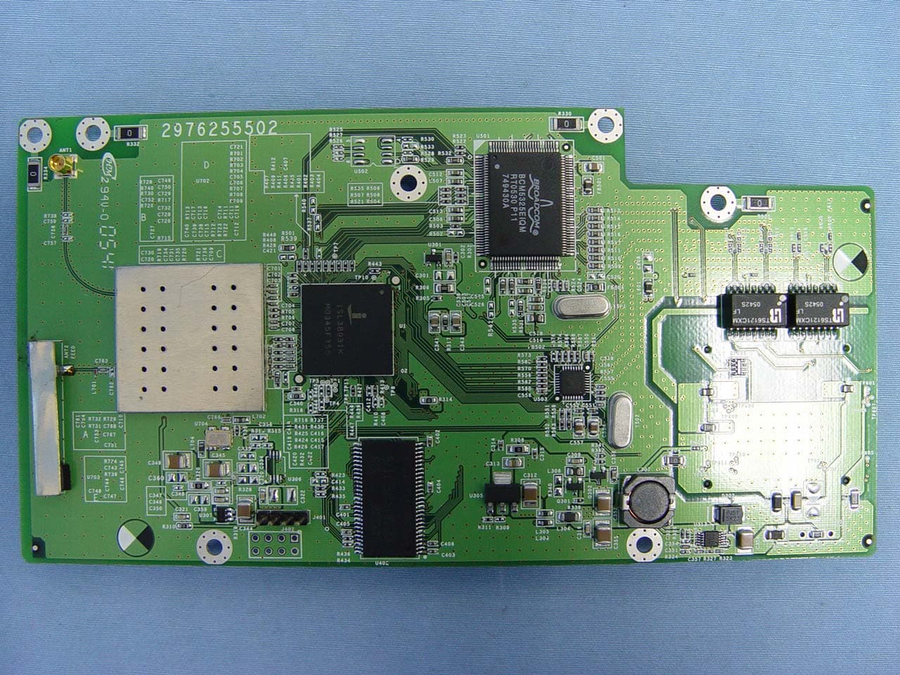
Click to zoom
Application Details
- Equipment Class
- DTS - Digital Transmission System
- Date of Grant
- Dec 19, 2005
- Application Purpose
- Original Equipment
- Date of Application
- Dec 19, 2005
- Equipment Note
- 802.11b/g WiFi Module
- Frequency Range
- 2412.00000000 - 2462.00000000
- Company
- Delta Electronics, Inc.
- Country
- Taiwan
Documents & Files
Document Text
Text extracted from the exhibit documents filed with the FCC. Open a document above to read the original.
Users Manual
ProST IEEE802.11b/g WiFi Board Preliminary Reference Guide Rev: 1.00 Date: August 31, 2005 Total Manufacturing Test Process Overview: In general the following steps are considered part of a manufacturing (test) flow: 1. PCBA assembly 2. Inspection(visual, automated visual, X-ray, ) 3. Structural test of the digital circuitry(Boundary Scan Test (BST), or other methods) 4. Functional test of the analog circuitry (radio test). 5. Calibration of the radio (for optimal performance within legal bounds); storing the results to non-volatile memory. 6. Customization/ serialization (adding identity such as Part number to the DUT). 7. Plastics assembly. 8. Pack & ship. Figure 1. Manufacturing Test Process Manufacturing Test Plan Overview for IMT tool 1. Test initialization and Product identification PCB serial number, product part number, and MAC address are established. A bar code scanner or the keyboard can be used to enter this information By default the information is divided between two codes. The first (bar) code contains the PCB serial number. The second bar code contains the product part number and half the Mac address. 2. DUT insertion Depending on the type of DUT, the software waits for the DUT to be attached to the set-up. If the DUT is not responding, the user is offered an escape by pressing the ABORT button. Alternatively the user is asked to insert the DUT and press the NEXT button. The software then switches the DUT on, and continues with the testing. 3. System test Properties of the operating system, including the version number, are determined and tested for compatibility. The versions of a number of DLLs and other system files are checked for compatibility as well. 4. Firmware and Driver Compatibility test The MTFW version number is tested for compatibility. 5. Transmitter verification A quick test is performed to verify the transmit function of the DUT. If the DUT passes this test, the following is true: the test system can communicate with the DUT firmware. The DUT can transmit RF signals with approximately the right frequency and amplitude. 6. Frequency accuracy The carrier frequency accuracy of the DUT is determined at the center channel. The sum of the measured deviation plus the maximum instrument error must be less than the limit set by the 802.11 standard 7. Receiver verification The capability of the receiver circuitry to receive and demodulate 802.11 packets is verified. If the DUT passes, the following is true: the receiver functions correctly and the receiver sensitivity(PER) is within limits. As part of this test the GRT output power is measured, the RF isolation between GRT and DUT is verified, and interference from other 802.11 sources is detected. 8. RSSI calibration (linear approximation) Linear curve fitting is performed on the result, and PDR 0x1902, 0x1905, or 0x1908 is calculated, depending on the platform type. 9. PA control loop calibration The PA control loop behavior is measured as a function of modulation type (bit rate) and channel (frequency). Depending on the platform, PDR 0x1901 or 0Xpdr1903 and 0x1904 are calculated. There are two implementations for this step: 1. PA Calibration 2. PA Curves and PA limits Besides, we have max/min output power pass/fail criteria for different modulation as Figure2 in 9301A_param configured file. Figure2. Power Limit 10. TX IQ Calibration For the platforms that require it, ZIF TX IQ Calibration is performed. 11. NV initialize By default this test will (re-)initialize and therefore erase the non-volatile memory. 12. Upload files to flash Files can be uploaded to AP based products. These files can contain firmware images, boot loaders or custom made images. 13. Write PDA The PDRs that were generated by the other test modules are written to the PDA that resides in the non-volatile memory of the DUT. 802.11b/g WiFi Module Features The features supported by the ProST 802.11g WLAN Access Point are outlined below: Interfaces directly to 10/100Mbps IEEE 802.3 Ethernet networks Supports IEEE 802.11 WLAN functions Supported WLAN Bridge function (WDS: Wireless Distribution System) Firmware is stored in a flash memory and can be upgraded remotely. Configurable through Web based management. Power, Ethernet and wireless activity LED indicators. One external and one internal inverted F antennas supporting diversity. Wireless Network Configuration Ad-hoc Mode (Peer-to-Peer Workgroup) The Institute of Electrical and Electronics Engineers (IEEE) standard for wireless LANs ( WLANs), 802.11, offers two methods for configuring a wireless network — ad hoc and infrastructure. In an ad hoc network, computers are brought together as needed; thus, there is no structure or fixed points to the network — each node can generally communicate with any other node. There is no access point involved in this configuration. It enables you to quickly set up a small wireless workgroup and allows workgroup members to exchange data or share printers as supported by Microsoft Networking in the var ious Windows operating systems. Some vendors also refer to ad hoc networking as Peer-to-Peer group networking. In this configuration, network packets are directly sent and received by the intended transmitting and receiving stations. As long as the stations are within range of one another, this is the easiest and least expansive way to set up a wireless network. To set up an ad hoc workgroup operating with standard protocols, do the following: • Set all stations to connect in Ad-hoc mode (or Peer-to-Peer workgroup mode) • Set all stations to use the same network name (or SSID). • Set all stations to use no WEP encryption key or an identical WEP encryption key • Set all stations to use the same wireless channel for communication Infrastructure Mode To set up an infrastructure network operating with standard protocols, do the following: •Set all wireless stations to connect in infrastructure mode •Set all stations to use the same network name (or SSID) •Set all statio…
Text truncated - open the document above for the full version.
Users Manual
802.11b/g WiFi Module port range, enter the first and last port number in the range into the edit boxes. For TCP traffic, you can also select specific flags. Use this to block only incoming TCP traffic (for example telnet), but allow outgoing (from LAN to WAN) traffic. To do th is, check the Match TCP flags check box, and set these flags: SYN radio button to Yes, ACK to NO, RST to NO. OKSave the rule and return. CancelReturn without save the rule. z Management information The Management Information shows: Change Password Change Password Current PasswordUsers may need to enter the present password to allow change the new password 802.11b/g WiFi Module Set PasswordUser s set a new password for this device Repeat New PasswordTo confirm your previous entry are identity characters Restore Default PasswordTo restore new password in the memory ApplyMeans once you change the parameters and press apply to save the values. CancelMeans you leave it un-changed. Upgrade Firmware Upgrade Firmware PasswordUsed for upgrade. BrowseUsers may define the upgraded file location on the system directory UpgradePress Upload for downloading the new firmware version on the device 802.11b/g WiFi Module Restore Factory Default Restore Factory Default Restore factory defaultUsers may call back the initial default setting parameters by select “ Yes” and click “ Apply” . CancelMeans you leave it un-change d 802.11b/g WiFi Module Boot Selection Boot Selection Slot 1, 2There are two images of different releases in the flash. One stays at a place called Slot 1 while another stays at Slot 2. They are non-relative with each other. You can choose one of them to boot from. Reboot APYou may select Slot 1 or Slot 2 to boot from that slot, and select AP or Router to boot to that mode. Then click on “Apply” button to reboot the access point. It will boot from the Slot in the mode from your choose; and it will always boot like this until you make different changes again. CancelMeans you leave it un-change d. 802.11b/g WiFi Module z Advanced Configuration Allow advanced users to set up RTS (Request to Send) Threshold packet size, Fragmentation Packet Length, Beacon Interval, VSS, VLAN, snmp trap, time protocol and so on. Wireless Settings Advance Wireless SettingModel ProST WLAN Access Point dot11OperationalRateSetIt specifies the set of data rates at which the station may transmit data. Each octet contains a value representing a rate. Each rate shall be within the range from 2 to 127, corresponding to data rates in increments of 500 kb/s from 1 Mb/s to 63.5 Mb/s, and shall be supported for receiving data. dot11BeaconPeriodSpecify the value for Beacon Interval. You can choose it between 1 and 65535. dot11RTSThresholdThe packet size that the wireless node uses to determine if it should use the CSMA/CD mechanism or the CSMA/CA mechanism fo r packet transmission. With the CSMA/CD transmission mechanism, the transmitting station sends out the actual packet as soon as it has waited for the silence period. With the CSMA/CA transmission mechanism, the transmitting station sends out a RTS packet to the receiving station, waits for the receiving station to send back a CTS packet before sending the actual packet data. You can choose it between 0 and 2347. dot11FragmentationThresholdThis is the packet length used for fragmentationPackets larger than the size 802.11b/g WiFi Module programmed in this field will be fragmented. The Fragment Threshold value must be larger than RTS Threshold value. You can choose it from 256 to 2346. ApplyMeans once you change the parameters and press apply to save the values. CancelMeans you leave it un-changed. Virtual Service Sets Virtual Service Sets VSSIDIt indicates the VLAN number with which the frames are tagged when sent on a VLAN. SSIDSet a wireless network name ( SSID: Service Set Identifier) EnabledIndication the status of Virtual Service Sets (Enable) Change ConfigurationChanges Virtual Service Sets on specified VLAN. Click it will pop up a window likes the picture above with values filled. Change SecurityChange the security configuration of Virtual Service Sets. You can consult “ Wireless Security Settings” above for more details about security configuration. AddAdd Virtual Service Sets on specify VLANClick it will pop up a window just the same 802.11b/g WiFi Module as in the picture above. DeleteDelete existed Virtual Service Sets on specify VLAN. Create BridgeIf you want to make an VSS works as an bridge, please choose that VSS and click “Create Bridge” . VLAN Settings VLAN Settings VLAN Version Number Means which VLAN version is in use. Maximum value of VLANID Supported The maximum value you can give to your VLAN as an ID. For it is 4094, you can’ t give a value bigger than 4094 or less than 0. Maximum number of VLANs supported How many VLANs your system can support. In this case, you can create no more than 32 ones. Current number of VLANsHow many VLANs you have now. SelectSelect the Virtual LAN. VLAN IDA VLAN number, packet with tagged when packet send VLAN NameName identifying the VLAN. Needs to be unique across the VLANS created. 802.11b/g WiFi Module Tagged PortsIndicates the VLAN interfaces on which all packets will be received/transmitted tagged. Untagged PortsIndicates the VLAN interfaces on which all untagged packets received, are transmitted to the specified VLAN. Similarly any packet received on any other interface for this VLAN is transmitted untagged on this interface. Wireless PortsIndicate the wireless interfaces that are added on the VLAN such that any traffic received on the wireless interface is transmitted to the corresponding VLAN on the appropriate VLAN interface and any traffic received for this VLAN from the VLAN interface is transmitted as untagged 802.11 frames on the wireless interface. AddAdd more VLANs: VLAN ID : give a number between 1 and 4094 as the VLAN ID. VLAN Name : give no more than 32 characters as the VLAN's name. Tagged Ports : choose which port…
Text truncated - open the document above for the full version.
Cover Letter(s)
Helen Zhao Subject: FW: Re : RE: Re : RE: Re : RE: Re : FW: DELTA NETWORKS, INC., FCC ID: PD5TYPEIII, Assessment NO.: AN05T5355, Notice#1 12/20/2005 -----Original Message----- From: amanda.wu [mailto:[email protected]]On Behalf Of application Sent: Tuesday, December 20, 2005 12:22 AM To: Helen Zhao Subject: Re : RE: Re : RE: Re : RE: Re : FW: DELTA NETWORKS, INC., FCC ID: PD5TYPEIII, Assessment NO.: AN05T5355, Notice#1 Dear Helen: Please my reply as below. Thank you!! Regarding question#1, after discussion, client decided to apply for modulal approval. Attached please find the user manual. Please check. Regarding question#2, In this case, the internal antenna and external diople antenna will be connected with EUT all the time but not optional. Moreover, why the output power measured would be different is because the antenna terminator and cable loss are different for internal and external antenna. Different power setting with different antenna is not because of reducing output power to comply with FCC limit. The external antenna connector is mounted on the main PCB not via cable. During RF conducted tests, the measuring point was made at external antnena connector. There is no need for end user to reduce the output power to comply with FCC limits. Since the measured points are different, we just think it's better to report two of them. MPE estimate was calculated with highest antenna gain without cable loss. During the radiated spurious and restricted band edge tests, the antenna cable used is less than 20 cm in length with approx. 2 dB loss. In the actual installation, the cable lenght will be longer than the cable length used during the tests. With above information provided, we do not think grant note 36 should apply . Additional Question: Please provide one more antenna port conducted test setup photo when measured at the end of internal antenna. Ans: Attached please find the revised set up for photo for additional conducted test set up photo. Also, because the NB pc used for testing internal antenna port's output power is different from external, test report page 11 of the support equipment has been modified as well. Best Regards, Amanda -----Original Message----- From: Compliance Certification Services [mailto:[email protected]] Sent: Wednesday, December 14, 2005 3:27 PM Subject: DELTA NETWORKS, INC., FCC ID: PD5TYPEIII, Assessment NO.: AN05T5355, Notice#1 Question #1: This module meets all eight modular approval criteria, is qualified to get full modular approval, but the modular approval cover letter applies for a limited modular approval. There is a cover letter in the filing to explain why the system manual can replace module manual for certification filing. Unfortunately, it is not acceptable. 1) This module is not used and installed in Delta Network systems, it is sold to Airspan, so OEM installation manual is required. 2) The test report and test setup photos all shows the device was tested stand-alone, has nothing to do with the system. Please submit a user manual for the module. Question #2: The test report provides two sets of RF conducted test data, one for external 2 dBi external antenna, one for 1.77dBi internal antenna. It shows the power output is reduced when using 2dBi external antenna. In that case, a grant note "36 - Certain antennas used with this equipment require a minimum cable length, or have output power limitations as documented in the application." will be added on the grant. This will require professional installation, and based on FCC modular approval policy, any device requiring professional installation won't be granted a modular approval. Please let me know if you wish to modify the test report or change for a system approval. Best Regards, Helen Zhao The items indicated above must be submitted before processing can continue on the above referenced application. Failure to provide the requested information within 30 days of the original e-mail date may result in application dismissal and forfeiture of the filing fee. Also, please note that partial responses increase processing time and should not be submitted. Any questions about the content of this correspondence should be directed to the e-mail address listed below the name of the sender. 12/20/2005
External Photos
Compliance Certification Services Inc. Report No: 51103004 Date of Issue: November 25, 2005 Page 1 Total Page: 3 Rev. 00 EXTERNAL PHOTOGRAPHS OF EUT PIFA Antenna
ID Label/Location Info
Contains RF module FCC ID : PD5TYPEIII FCC ID: PD5TYPEIII This device complies with Part 15 of the FCC Rules. Operation is subject to the following two conditions: (1) this device may not cause harmful interference and (2) this device must accept any interference received, including interference that may cause undesired operation. Airspan TYPEIII
Internal Photos
Compliance Certification Services Inc. Report No: 51103004 Date of Issue: November 25, 2005 Page 2 Rev.00 INTERNAL PHOTOGRAPHS OF EUT Compliance Certification Services Inc. Report No: 51103004 Date of Issue: November 25, 2005 Page 3 Rev.00 Dipole Antenna
Parts List/Tune Up Info
WHA YU INDUSTRIAL CO., LTD. (HEAD OFFICE) SUPERGRADE INTERNATIONAL ENTERPRISE LTD. (SHANGHAI) SPECIFICATION FOR APPROVAL MANUFACTURERCUSTOMER SIGNATURESIGNATURE APPROVE D BY : WHA YU GROUP WHA YU INDUSTRIAL CO., LTD.(HEAD OFFICE) Address: No.326, Sec.2, Kung Tao 5 Rd., Hsin Chu City, Taiwan, R.O.C. DATE : Tel:+886-3-5714225 (REP.) Fax:+ 886-3-5713853+ 886-3-5723600 W. Y. P/NO C529-540207-A REV PART NO REVISION CUSTOMER PART NAME : outdoor 2dBi ANTENNA VSWR -20 -15 -10 -5 0 5 0 30 60 90 120 150 180 210 240 270 300 330 -20 -15 -10 -5 0 5 Vertical Plane Co-polarization Patterns 2.40 GHz 2.45 GHz 2.50 GHz -20 -15 -10 -5 0 5 0 30 60 90 120 150 180 210 240 270 300 330 -20 -15 -10 -5 0 5 Horizontal Plane Co-polarization Patterns 2.40 GHz 2.45 GHz 2.50 GHz
Test Report
Compliance Certification Services Inc. Report No.: 51103004-RP1 FCC ID: PD5TYPEIII Date of Issue: November 25, 2005 Note: This report shall not be reproduced except in full, without the written approval of Compliance Certification Services Inc. This document may be altered or revised by Compliance Certification Services Inc. personnel only, and shall be noted in the revision section of the document. Page 1 Total Page: 91 Rev. 00 FCC 47 CFR PART 15 SUBPART C TEST REPORT For 802.11b/g WiFi Module Model: TYPE III Trade Name: Airspan Issued to DELTA NETWORKS, INC. 252, Shang Ying Road, Kuei San Industrial Park, Taoyuan Shien 33341,Taiwan, R.O.C. Issued by Compliance Certification Services Inc. No. 81-1, Lane 210, Bade Rd. 2, Luchu Hsiang, Taoyuan Hsien, (338) Taiwan, R.O.C. http://www.ccsemc.com.tw [email protected] Compliance Certification Services Inc. Report No.: 51103004-RP1 FCC ID: PD5TYPEIII Date of Issue: November 25, 2005 Page 2 Rev. 00 TABLE OF CONTENTS 1. TEST RESULT CERTIFICATION........................................................................................................3 2. EUT DESCRIPTION..............................................................................................................................4 3. TEST METHODOLOGY.......................................................................................................................5 3.1 EUT CONFIGURATION........................................................................................................................5 3.2 EUT EXERCISE....................................................................................................................................5 3.3 GENERAL TEST PROCEDURES.............................................................................................................5 3.4 FCC PART 15.205 RESTRICTED BANDS OF OPERATIONS........................................................6 3.5 DESCRIPTION OF TEST MODES...........................................................................................................7 4. INSTRUMENT CALIBRATION...........................................................................................................8 4.1 MEASURING INSTRUMENT CALIBRATION......................................................................................8 4.2 MEASUREMENT EQUIPMENT USED.........................................................................................8 5. FACILITIES AND ACCREDITATIONS ..............................................................................................9 5.1 FACILITIES .... ....................................................................................................................................9 5.2 EQUIPMENT........................................................................................................................................9 5.3 LABORATORY ACCREDITATIONS AND LISTING..................................................................................9 5.4 TABLE OF ACCREDITATIONS AND LISTINGS.....................................................................................10 6. SETUP OF EQUIPMENT UNDER TEST...........................................................................................11 6.1 SETUP CONFIGURATION OF EUT.......................................................................................................11 6.2 SUPPORT EQUIPMENT ...............................................................................................................11 7. FCC PART 15.247 REQUIREMENTS................................................................................................12 7.1 6DB BANDWIDTH.............................................................................................................................12 7.2 PEAK POWER....................................................................................................................................20 7.3 AVERAGE POWER............................................................................................................................28 7.4 BAND EDGES MEASUREMENT ................................................................................................36 7.5 PEAK POWER SPECTRAL DENSITY....................................................................................................53 7.6 SPURIOUS EMISSIONS ................................................................................................................61 7.7 POWERLINE CONDUCTED EMISSIONS...............................................................................................84 APPENDIX 1 RADIO FREQUENCY EXPOSURE ..................................................................................87 APPENDIX 2 PHOTOGRAPHS OF TEST SETUP...................................................................................89 Compliance Certification Services Inc. Report No.: 51103004-RP1 FCC ID: PD5TYPEIII Date of Issue: November 25, 2005 Page 4 Rev. 00 2. EUT DESCRIPTION Product 802.11b/g WiFi Module Trade Name Airspan Model Number TYPE III Model Discrepancy N/A Power Supply Model: DV-151A-1 I/P: AC 120V, 60Hz, 22W O/P: DC 12V, 1.2A Frequency Range 2412 ~ 2462 MHz Transmit Power External Antenna: IEEE 802.11b: 18.31 dBm IEEE 802.11g: 18.97 dBm Internal Antenna: IEEE 802.11b: 18.99 dBm IEEE 802.11g: 20.05 dBm Modulation Technique IEEE 802.11b: DSSS (CCK, DQPSK, DBPSK) IEEE 802.11g: DSSS (CCK, DQPSK, DBPSK) + OFDM (QPSK, BPSK, 16-QAM, 64-QAM) Transmit Data Rate IEEE 802.11b: 11, 5.5, 2, 1 Mbps IEEE 802.11g: 54, 48, 36, 24, 18, 12, 11, 9, 6, 5.5, 2, 1 Mbps Number of Channels 11 Channels Antenna Specification External Antenna: Dipole Antenna / Gain: 2 dBi Internal Antenna: PIFA Antenna / Gain: 1.77 dBi Remark: 1. The sample selected for test was engineering sample that approximated to production product and was provided by manufacturer. 2. This submittal(s) (test report) is intended for FCC ID: PD5TYPEIII filing to comply with S…
Text truncated - open the document above for the full version.
Test Setup Photos
Compliance Certification Services Inc. Report No.: 51103004-RP1 FCC ID: PD5TYPEIII Date of Issue: November 25, 2005 Page 89 Rev. 00 APPENDIX 2 PHOTOGRAPHS OF TEST SETUP Conducted Emissions Setup Photos Compliance Certification Services Inc. Report No.: 51103004-RP1 FCC ID: PD5TYPEIII Date of Issue: November 25, 2005 Page 90 Rev. 00 Radiated Emissions Setup Photos Compliance Certification Services Inc. Report No.: 51103004-RP1 FCC ID: PD5TYPEIII Date of Issue: November 25, 2005 Page 91 Rev. 00 Powerline Conducted Emissions Setup Photos
Contact Information
Applicant
Payton Ting(Manager)
Test Firm
Compliance Certification Services Inc.Kurt Chen
Technical Specifications
| # | Rule Parts | Frequency Range | Power Output |
|---|---|---|---|
| 1 | 15C | 2.41 GHz - 2.46 GHz | 101.16 mW |
Other Applications from Delta Electronics, Inc.
PD5-NWA1200
Jun 16, 2026Indoor Wireless AP
Equipment Class
DTS - Digital Transmission SystemPD5-AP743
Jun 03, 2026802.11be enterprise access point
Equipment Class
NII - Unlicensed National Information Infrastructure TXPD5-AP623E
Sep 04, 2025802.11ax enterprise access point
Equipment Class
NII - Unlicensed National Information Infrastructure TX
PD5-LM-WESA04OR
Aug 01, 2021802.11 b/g/n/ac WIFI AP
Equipment Class
NII - Unlicensed National Information Infrastructure TX
PD5-NWA1000
Jul 25, 2021Wireless Access Point
Equipment Class
NII - Unlicensed National Information Infrastructure TX