PDEMEDIOL120Base station for tracking system used with tags
TAGSYS Australia Pty Ltd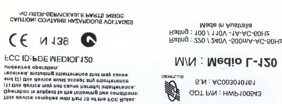
Click to zoom
Application Details
- Equipment Class
- DXX - Part 15 Low Power Communication Device Transmitter
- Date of Grant
- Feb 25, 2001
- Application Purpose
- Original Equipment
- Date of Application
- Feb 25, 2001
- Equipment Note
- Base station for tracking system used with tags
- Frequency Range
- 13.55300000 - 13.56700000
- Company
- TAGSYS Australia Pty Ltd
- Country
- Australia
Documents & Files
Document Text
Text extracted from the exhibit documents filed with the FCC. Open a document above to read the original.
Users Manual
GemWave™ C220 Chip & Medio L120/L121 Technical Description Version 1.0 GEMPLUS March 22 2000 C220 Chips & L120/L121 Couplers - Technical Description Version 1.0 GEMPLUS COMPANY CONFIDENTIAL Page 2 CONTENTS GEMWAVE L120/L121 SMART TRACKING........................................................................2 1 THEORY OF OPERATION...................................................................................................2 2 COMPARISON WITH LOW FREQUENCY SYSTEMS....................................................................4 3 GEMWAVE SMART LABELS...............................................................................................4 4 GEMWAVE ANTENNAS.....................................................................................................5 4.1 Antenna field regions............................................................................................6 4.2 External loop antenna (Standard)...........................................................................7 4.3 Dual polarized loop antenna..................................................................................7 4.4 Truck mounted loop antenna.................................................................................8 4.5 AC206 Metal mounted antenna..............................................................................8 5 GEMWAVE MEDIO L120/L121 COUPLERS........................................................................9 51 Coupler functions..................................................................................................9 5.2 System construction...........................................................................................10 53 RF Section..........................................................................................................10 54 CPU Section.......................................................................................................13 5.5 Power Supply......................................................................................................16 GEMWAVE C220 & L120/L121 SMART TRACKING The GemWave Smart Tracking system offers extremely low cost smart labels for use in shorter read range high volume areas such as library book identification, transport and logistical labels, waste management etc. Read range is limited to around 500-mm but the system offers very high read rates (up to 70 times per second) making it ideal for use on high speed production lines. Standard Features for these systems include: • Low Cost Smart Labels • High Read Speed • High immunity to industrial noise • Full I/O capabilities • Networking capabilities 1Theory of operation The operation of the system can be explained by considering the three major components of the system. These are the coupler, the antenna and the smart label. C220 Chips & L120/L121 Couplers - Technical Description Version 1.0 GEMPLUS COMPANY CONFIDENTIAL Page 3 When a smart label is to be read, the coupler transmits an electromagnetic signal to the labels via the antenna(s). Some of the transmitted energy is incident on the label, some of this RF (AC) energy is then rectified into a DC level and used to power the microchip while the remainder is used to carry the smart label’s unique code back to the coupler. The process of superimposing the smart labels unique code onto the carrier frequency is referred to as modulation. In total, 128 bits 1 are transmitted including error detection information, taking a typical time of 2.4 or 1.2ms (for long and short modes respectively). This data is picked up by the antenna and decoded. The decoding process occurs in real time in order to maximize the multiple label reading capabilities of the L120/L121 couplers. The power transfer mechanism between the smart label and the coupler is quite unique and is worthy of a brief discussion. It can easily be shown that the power transfer ratio of a near field interrogation system is given by Pr P kQQ t tr= 2 Where Pris the power received by the smart label. Ptis the power transmitted by the antenna. k is the coefficient of coupling. Qris the quality factor of the smart label antenna. Qtis the quality factor of the transmit antenna. Thus in order to maximize the received power within the smart label the quality factors of both the interrogator and the smart label antennas should be made as high as possible. Practical limitations to this include allowing enough bandwidth to pass the reply sidebands and the susceptibility of the antenna to detuning due to environmental influences. Furthermore, in this type of system, a signal power fall off of approximately 60.log(distance) applies. This implies that the field strength is high in the immediate vicinity of the antenna but a very low level exists in the far field, hence well confined interrogation regions can be easily created. Under these conditions, it can be shown that sixty four times more input power to the antenna is required to double the read range. When specifying GemWave C220 systems, it is important to keep in mind the vortex nature of magnetic fields. This implies always ensuring an adequate path for the field to circulate. It is also equally important to have a clear understanding of the field patterns produced by these antennas to ensure that the smart labels are in the correct orientation to read. For the best performance, the smart labels C220 Chips & L120/L121 Couplers - Technical Description Version 1.0 GEMPLUS COMPANY CONFIDENTIAL Page 4 must always have their coil perpendicular to the direction of the field. If the smart label is placed parallel to the field it will receive no power and will not work. 2Comparison with low frequency systems At these relatively low frequencies (13.56 MHz) there are several operational characteristics that make these systems attractive for many applications. Perhaps, the most significant of these is cost. Since at these frequencies all the necessary components have been completely integrated…
Text truncated - open the document above for the full version.
Attestation Statements
Professional Installation Statement The unit and antenna are typically built into a library borrowing station, so it is impossible to remove or disconnect the antenna without unbolting and removing the entire reader from the borrowing station. Application The unit is a RFID reader for library borrowing stations. Installation The unit is only installed by Gemplus approved and trained partners. Marketing The unit is only marketed and sold through Gemplus and approved partners. It is not available for public sale. Gerard Rankin Gemplus Tag Australia Ground Floor 212 Pirie Street ADELAIDE SA 5000 Australia PO Box 99 RUNDLE MALL ADELAIDE SA 5000 AUSTRALIA Tel: +61 8 8223 5802 Fax: +61 8 8232 3720 Email: [email protected] URL: www.gemplus.com
Cover Letter(s)
PO Box 99, Rundle Mall SA 5000, Ground Floor, 212 Pirie Street, Adelaide SA 5000, AUSTRALIA Tel +618-8100 8300 Fax +618-8232 3720 - Internet : http://www.tagsys.net Federal Communication Commission Equipment Authorization Division Application Processing Branch 7435 Oakland Mills Road Columbia, MD 21045 28th August 2002 Reference: FCC ID: PDEMEDIOL120 Subject: Request for confidentiality for FCC Certification Application – TAGSYS Australia Pty Ltd - Low power transmitter (Long Range Reader - Medio L120) Pursuant to Rule 47 CFR, Chapter 1, Section 0.459, TAGSYS Australia Pty Ltd, requests that the following detailed technical data regarding the Medio L120 (Long Range Reader), be classified and deemed confidential by the Federal Communications Commission (FCC) and as such be withheld from public inspection. Pursuant to 47 CFR, Chapter 1, Section 0.457, the exhibits contain details of trade secrets and technical data that is not made available to competitors and the general public. This information is treated in a confidential manner by TAGSYS Australia Pty Ltd. and guarded from disclosure to our competitors. The exhibits outlined are not routinely made available to TAGSYS Australia Pty Ltd staff, with such access granted only to those specifically involved with this particular project. All employees treat this technical documentation in a confidential manner. The manufacture of this product has taken place after an extensive research and development process that has seen the company invest a considerable amount of time and money. The time and effort taken has enabled the product to meet the specific demands of the competitive market for which it is intended and it would be therefore detrimental to allow competitors easy access to design and development details. Apart from a limited number of employees, the information has previously only been disclosed to the Test House responsible for conducting testing and authorized to act as our agent during the Certification process. Page 2 of 2 PO Box 99, Rundle Mall SA 5000, Ground Floor, 212 Pirie Street, Adelaide SA 5000, AUSTRALIA Tel +618-8100 8300 Fax +618-8232 3720 - Internet : http://www.tagsys.net The following information submitted as part of the FCC certification process should be held confidential: Exhibit - PCB Layouts 47 CFR 2.1033(c)10 Complete technical PCB Layouts Exhibit – Schematics 47 CFR 2.1033(c)10 Complete technical schematic circuit diagrams Exhibit – Block Diagram 47 CFR 2.1033 Detailed technical RF block diagram Sincerely Yours, Alfio Grasso Technical Manager TAGSYS Australia Pty Ltd
External Photos
FCC ID: PDEMEDIOL120 EMC Technologies Report No. M000840FCC FCC ID LABEL & LOCATION ______________________________________________________________________________________________ 5292 This Laboratory is accredited by the National Association of Testing Authorities, Australia. The tests reported herein have been performed in accordance with its terms of accreditation for FCC Part 15. This document shall not be reproduced, except in full.
External Photos
FCC ID: PDEMEDIOL120 EMC Technologies Report No. M000840FCC FCC ID LABEL & LOCATION ______________________________________________________________________________________________ 5292 This Laboratory is accredited by the National Association of Testing Authorities, Australia. The tests reported herein have been performed in accordance with its terms of accreditation for FCC Part 15. This document shall not be reproduced, except in full.
ID Label/Location Info
FCC ID: PDEMEDIOL120 EMC Technologies Report No. M000840FCC FCC ID LABEL & LOCATION ______________________________________________________________________________________________ 5292 This Laboratory is accredited by the National Association of Testing Authorities, Australia. The tests reported herein have been performed in accordance with its terms of accreditation for FCC Part 15. This document shall not be reproduced, except in full.
ID Label/Location Info
FCC ID: PDEMEDIOL120 EMC Technologies Report No. M000840FCC FCC ID LABEL & LOCATION ______________________________________________________________________________________________ 5292 This Laboratory is accredited by the National Association of Testing Authorities, Australia. The tests reported herein have been performed in accordance with its terms of accreditation for FCC Part 15. This document shall not be reproduced, except in full.
Internal Photos
FCC ID: PDEMEDIOL120 EMC Technologies Report No. M000840FCC-R ______________________________________________________________________________________________ 5292 This Laboratory is accredited by the National Association of Testing Authorities, Australia. The tests reported herein have been performed in accordance with its terms of accreditation for FCC Part 15. This document shall not be reproduced, except in full. APPENDIX B4 PHOTOGRAPHS OF TEST SAMPLE Internal Photos FCC ID: PDEMEDIOL120 EMC Technologies Report No. M000840FCC-R ______________________________________________________________________________________________ 5292 This Laboratory is accredited by the National Association of Testing Authorities, Australia. The tests reported herein have been performed in accordance with its terms of accreditation for FCC Part 15. This document shall not be reproduced, except in full. APPENDIX B5 PHOTOGRAPHS OF TEST SAMPLE Internal Photos FCC ID: PDEMEDIOL120 EMC Technologies Report No. M000840FCC-R ______________________________________________________________________________________________ 5292 This Laboratory is accredited by the National Association of Testing Authorities, Australia. The tests reported herein have been performed in accordance with its terms of accreditation for FCC Part 15. This document shall not be reproduced, except in full. APPENDIX B6 PHOTOGRAPHS OF TEST SAMPLE Internal Photos
Internal Photos
FCC ID: PDEMEDIOL120 EMC Technologies Report No. M000840FCC-R ______________________________________________________________________________________________ 5292 This Laboratory is accredited by the National Association of Testing Authorities, Australia. The tests reported herein have been performed in accordance with its terms of accreditation for FCC Part 15. This document shall not be reproduced, except in full. APPENDIX B4 PHOTOGRAPHS OF TEST SAMPLE Internal Photos FCC ID: PDEMEDIOL120 EMC Technologies Report No. M000840FCC-R ______________________________________________________________________________________________ 5292 This Laboratory is accredited by the National Association of Testing Authorities, Australia. The tests reported herein have been performed in accordance with its terms of accreditation for FCC Part 15. This document shall not be reproduced, except in full. APPENDIX B5 PHOTOGRAPHS OF TEST SAMPLE Internal Photos FCC ID: PDEMEDIOL120 EMC Technologies Report No. M000840FCC-R ______________________________________________________________________________________________ 5292 This Laboratory is accredited by the National Association of Testing Authorities, Australia. The tests reported herein have been performed in accordance with its terms of accreditation for FCC Part 15. This document shall not be reproduced, except in full. APPENDIX B6 PHOTOGRAPHS OF TEST SAMPLE Internal Photos
Internal Photos
FCC ID: PDEMEDIOL120 EMC Technologies Report No. M000840FCC-R ______________________________________________________________________________________________ 5292 This Laboratory is accredited by the National Association of Testing Authorities, Australia. The tests reported herein have been performed in accordance with its terms of accreditation for FCC Part 15. This document shall not be reproduced, except in full. APPENDIX B4 PHOTOGRAPHS OF TEST SAMPLE Internal Photos FCC ID: PDEMEDIOL120 EMC Technologies Report No. M000840FCC-R ______________________________________________________________________________________________ 5292 This Laboratory is accredited by the National Association of Testing Authorities, Australia. The tests reported herein have been performed in accordance with its terms of accreditation for FCC Part 15. This document shall not be reproduced, except in full. APPENDIX B5 PHOTOGRAPHS OF TEST SAMPLE Internal Photos FCC ID: PDEMEDIOL120 EMC Technologies Report No. M000840FCC-R ______________________________________________________________________________________________ 5292 This Laboratory is accredited by the National Association of Testing Authorities, Australia. The tests reported herein have been performed in accordance with its terms of accreditation for FCC Part 15. This document shall not be reproduced, except in full. APPENDIX B6 PHOTOGRAPHS OF TEST SAMPLE Internal Photos
Operational Description
GemWave™ C220 Chip & Medio L120/L121 Technical Description Version 1.0 GEMPLUS March 22 2000 C220 Chips & L120/L121 Couplers - Technical Description Version 1.0 GEMPLUS COMPANY CONFIDENTIAL Page 2 CONTENTS GEMWAVE L120/L121 SMART TRACKING........................................................................2 1 THEORY OF OPERATION...................................................................................................2 2 COMPARISON WITH LOW FREQUENCY SYSTEMS....................................................................4 3 GEMWAVE SMART LABELS...............................................................................................4 4 GEMWAVE ANTENNAS.....................................................................................................5 4.1 Antenna field regions............................................................................................6 4.2 External loop antenna (Standard)...........................................................................7 4.3 Dual polarized loop antenna..................................................................................7 4.4 Truck mounted loop antenna.................................................................................8 4.5 AC206 Metal mounted antenna..............................................................................8 5 GEMWAVE MEDIO L120/L121 COUPLERS........................................................................9 51 Coupler functions..................................................................................................9 5.2 System construction...........................................................................................10 53 RF Section..........................................................................................................10 54 CPU Section.......................................................................................................13 5.5 Power Supply......................................................................................................16 GEMWAVE C220 & L120/L121 SMART TRACKING The GemWave Smart Tracking system offers extremely low cost smart labels for use in shorter read range high volume areas such as library book identification, transport and logistical labels, waste management etc. Read range is limited to around 500-mm but the system offers very high read rates (up to 70 times per second) making it ideal for use on high speed production lines. Standard Features for these systems include: • Low Cost Smart Labels • High Read Speed • High immunity to industrial noise • Full I/O capabilities • Networking capabilities 1Theory of operation The operation of the system can be explained by considering the three major components of the system. These are the coupler, the antenna and the smart label. C220 Chips & L120/L121 Couplers - Technical Description Version 1.0 GEMPLUS COMPANY CONFIDENTIAL Page 3 When a smart label is to be read, the coupler transmits an electromagnetic signal to the labels via the antenna(s). Some of the transmitted energy is incident on the label, some of this RF (AC) energy is then rectified into a DC level and used to power the microchip while the remainder is used to carry the smart label’s unique code back to the coupler. The process of superimposing the smart labels unique code onto the carrier frequency is referred to as modulation. In total, 128 bits 1 are transmitted including error detection information, taking a typical time of 2.4 or 1.2ms (for long and short modes respectively). This data is picked up by the antenna and decoded. The decoding process occurs in real time in order to maximize the multiple label reading capabilities of the L120/L121 couplers. The power transfer mechanism between the smart label and the coupler is quite unique and is worthy of a brief discussion. It can easily be shown that the power transfer ratio of a near field interrogation system is given by Pr P kQQ t tr= 2 Where Pris the power received by the smart label. Ptis the power transmitted by the antenna. k is the coefficient of coupling. Qris the quality factor of the smart label antenna. Qtis the quality factor of the transmit antenna. Thus in order to maximize the received power within the smart label the quality factors of both the interrogator and the smart label antennas should be made as high as possible. Practical limitations to this include allowing enough bandwidth to pass the reply sidebands and the susceptibility of the antenna to detuning due to environmental influences. Furthermore, in this type of system, a signal power fall off of approximately 60.log(distance) applies. This implies that the field strength is high in the immediate vicinity of the antenna but a very low level exists in the far field, hence well confined interrogation regions can be easily created. Under these conditions, it can be shown that sixty four times more input power to the antenna is required to double the read range. When specifying GemWave C220 systems, it is important to keep in mind the vortex nature of magnetic fields. This implies always ensuring an adequate path for the field to circulate. It is also equally important to have a clear understanding of the field patterns produced by these antennas to ensure that the smart labels are in the correct orientation to read. For the best performance, the smart labels C220 Chips & L120/L121 Couplers - Technical Description Version 1.0 GEMPLUS COMPANY CONFIDENTIAL Page 4 must always have their coil perpendicular to the direction of the field. If the smart label is placed parallel to the field it will receive no power and will not work. 2Comparison with low frequency systems At these relatively low frequencies (13.56 MHz) there are several operational characteristics that make these systems attractive for many applications. Perhaps, the most significant of these is cost. Since at these frequencies all the necessary components have been completely integrated…
Text truncated - open the document above for the full version.
Test Report
Page 1 of 36 EMI TEST REPORT for CERTIFICATION of FCC PART 15.225 TRANSMITTER FCC ID:PDEMEDIOL120 Manufacturer:Gemplus Tag Australia Pty Ltd Test Sample:Medio L120 Long Range Reader Report Number:M000840FCC-R (Replacement for Report M000840FCC) Issue Date:17 January 2000 This document must not be copied or reproduced, except in full without the written permission of the Manager, EMC Technologies Pty Ltd. Copyright is owned by EMC Technologies Pty Ltd. 5292 This Laboratory is accredited by the National Association of Testing Authorities, Australia. The tests reported herein have been performed in accordance with its terms of accreditation for FCC Part 15. EMC Technologies Pty Ltd A.C.N. 057 105 549 57 Assembly Drive Tullamarine Victoria Australia 3043 Ph: + 613 9335 3333 Fax: + 613 9338 9260 email: [email protected] FCC ID: PDEMEDIOL120 EMC Technologies Report No. M000840FCC-RPage 2 of 36 ______________________________________________________________________________________________ 5292 This Laboratory is accredited by the National Association of Testing Authorities, Australia. The tests reported herein have been performed in accordance with its terms of accreditation for FCC Part 15. This document shall not be reproduced, except in full. EMI TEST REPORT FOR CERTIFICATION OF FCC PART 15.225 TRANSMITTER FCC ID: PDEMEDIOL120 EMC Technologies Report Number: M000840FCC-R Date: 17 January 2001 CONTENTS 1. SUMMARY of TEST RESULTS 2. GENERAL INFORMATION 3. RADIATED EMI RESULTS 4. CONDUCTED EMI RESULTS 5. FREQUENCY TOLERANCE 6. CONCLUSION APPENDIX A. MEASUREMENT INSTRUMENTATION DETAILS APPENDIX B. TEST SAMPLE PHOTOGRAPHS APPENDIX C. TEST SAMPLE SCHEMATIC APPENDIX D. TEST SAMPLE PCB LAYOUTS APPENDIX E. TEST SAMPLE PCB OVERLAYS APPENDIX F. LABELLING - DRAWING AND LOCATION APPENDIX G. GRAPHS of EMI MEASUREMENT APPENDIX H. USER INSTRUCTIONS (MANUAL) FCC ID: PDEMEDIOL120 EMC Technologies Report No. M000840FCC-RPage 3 of 36 ______________________________________________________________________________________________ 5292 This Laboratory is accredited by the National Association of Testing Authorities, Australia. The tests reported herein have been performed in accordance with its terms of accreditation for FCC Part 15. This document shall not be reproduced, except in full. EMI TEST REPORT FOR CERTIFICATION OF FCC PART 15.225 TRANSMITTER Report Number:M000840FCC-R Test Sample:Long Range Reader Model Number:Medio L120 Serial Number:AC0030100162 Part Number:HWP100543 FCC ID: PDEMEDIOL120 Manufacturer:Gemplus Tag Australia Tested for:Gemplus Tag Australia First Floor, 99 Frome Street Adelaide SA 5000 Australia PO Box 99 Rundle Mall, SA 5000 Australia Phone:+ 61 8 8223 5802 Fax:+ 61 8 8223 3720 Responsible Party:Alfio Grasso Engineering Manager Gemplus Tag Australia Equipment Type:Intentional Radiator, Low Power Transmitter Test Standards:FCC Part 15 Section 225 Intentional Radiators. ANSI C63.4-1992 OET Bulletin No. 63 Test Dates:1 st to 14 th September 2000 Test Officer:Chieu Huynh Attestation:I hereby certify that the device(s) described herein were tested as described in this report and that the data included is that which was obtained during such testing. Authorised Signature:_________________ Chris Zombolas EMC Technologies Pty Ltd FCC ID: PDEMEDIOL120 EMC Technologies Report No. M000840FCC-RPage 4 of 36 ______________________________________________________________________________________________ 5292 This Laboratory is accredited by the National Association of Testing Authorities, Australia. The tests reported herein have been performed in accordance with its terms of accreditation for FCC Part 15. This document shall not be reproduced, except in full. EMI TEST REPORT FOR CERTIFICATION of FCC PART 15.225 TRANSMITTER Medio L120 Long Range Reader 1.0 SUMMARY of RESULTS This report details the results of EMI tests and measurements performed on the Medio L120 Long Range Reader in accordance with the Federal Communications Commission (FCC) regulations as detailed in Title 47 CFR, Part 15 Rules for intentional radiators. All results, and photographs of the EUT are detailed in this report. The EUT complied with requirements for fundamental frequencies and spurious emissions of section 15.225. Carrier Signal Field Strength:Complied, margin of 8.2 dB Out of Band Emissions:Complied, margin of 2.3* dB Conducted Emissions:Complied, margin of 1.0* dB Frequency Tolerance:Complied The measurement procedure was in accordance with ANSI C63.4-1992, and OET Bulletin No. 63. The instrumentation conformed to these requirements. * Refer to Secion 6.0 Conclusion 2.0GENERAL INFORMATION 2.1 General Description of Test Setup Test Sample:Long Range Reader Model Number:Medio L120 Serial Number:AC003010162 Part Number:HWP100543 FCC ID:PDEMEDIOL120 Equipment Type:Intentional Radiator, Low Power transmitter 2.2 Technical Specifications Refer to Appendix H for user instructions (manual) 2.3 Test sampe configurations The EUT was connected to HP Vectra PC via a 2m shielded RS232 cable. Monitor, mouse, keyboard and printer were connected to the PC. For the purpose of the test, an SMA-BNC antenna terminal connector was used. The EUT was configured to continuously transmit during the tests. Testing were performed twice: once with the EUT’s small antenna and once with its large antenna. The antennas were oriented to FCC ID: PDEMEDIOL120 EMC Technologies Report No. M000840FCC-RPage 5 of 36 ______________________________________________________________________________________________ 5292 This Laboratory is accredited by the National Association of Testing Authorities, Australia. The tests reported herein have been performed in accordance with its terms of accreditation for FCC Part 15. This document shall not be reproduced, except in full. maximise the emissions. Initial tests were first performed with the antennas flat on the table. The worst case was found to be with the transmitt antenna in the upright (vertical) position. 2.4Test …
Text truncated - open the document above for the full version.
Test Report
To: Curtis-Straus LLC From: Chris Zombolas Attn: Barry Quinlan Date: February 26, 2001 Pages: Re: Product Certification Application EMC Ref: M000840FCC-R FCC ID: PDEMEDIOL120 Dear Barry, Please find following our response to the outstanding issues: Item 1: Method of measurement for radiated emissions below 30 MHz- Please refer to our re-issue report M000840FCC-R, section 2.6 and 3.1.2 Item 2: Description of cables: All cables for PC, Printer, mouse and monitor were standard shielded cables. No ferrites were used. Item 3: Bandwidth Plot Please refer to plots – (Graphs 9 and 10) in report M000840FCC-R. Item 4: LISN details – EMCO 3825/2, 50 Ohm/50ìH S/n. 9506-2379 Item 5: Orientation of test sample - The EUT antenna was moved to maximize emissions Item 7: Agency agreement letter – Please refer to attachment Item 8: User Manual – The customer/manufacturer has confirmed that this is the installation/user manual that they supply. EMC Technologies Pty Ltd A.C.N. 057 105 549 57 Assembly Drive Tullamarine Victoria Australia 3043 Ph: + 613 9335 3333 Fax: + 613 9338 9260 email: [email protected] Item 9: FCC logo on label – Please refer to revised label artwork Item 10: Label material – Mylar (some minor additions made by Curtis-Straus based on later information – JDC) Best Regards Chris Zombolas
Test Setup Photos
FCC ID: PDEMEDIOL120 EMC Technologies Report No. M000840FCC-R ______________________________________________________________________________________________ 5292 This Laboratory is accredited by the National Association of Testing Authorities, Australia. The tests reported herein have been performed in accordance with its terms of accreditation for FCC Part 15. This document shall not be reproduced, except in full. APPENDIX B1 PHOTOGRAPHS OF TEST SETUP Radiated Emissions Test-Setup: Small Antenna FCC ID: PDEMEDIOL120 EMC Technologies Report No. M000840FCC-R ______________________________________________________________________________________________ 5292 This Laboratory is accredited by the National Association of Testing Authorities, Australia. The tests reported herein have been performed in accordance with its terms of accreditation for FCC Part 15. This document shall not be reproduced, except in full. APPENDIX B2 PHOTOGRAPHS OF TEST SETUP Radiated Emissions Test-Setup: Large Antenna FCC ID: PDEMEDIOL120 EMC Technologies Report No. M000840FCC-R ______________________________________________________________________________________________ 5292 This Laboratory is accredited by the National Association of Testing Authorities, Australia. The tests reported herein have been performed in accordance with …
Text truncated - open the document above for the full version.
Contact Information
Applicant
Alfio Grasso(Technical Manager)
Technical Contact
Non-Technical Contact
EMC TechnologiesChris Zombolas
[email protected]613933353333
Test Firm
EMC Technologies Pty. Ltd.Chris Zombolas
Technical Specifications
| # | Rule Parts | Frequency Range | Power Output | Tolerance |
|---|---|---|---|---|
| 1 | 15C | 13.553 MHz - 13.567 MHz | - | 0.0010000000 % |
Other Applications from TAGSYS Australia Pty Ltd
PDEMEDIOL122EAS
Jul 30, 2002Tag Reader
Equipment Class
DXX - Part 15 Low Power Communication Device Transmitter