PDHTX150MHANDHELD MARINE RADIO
TTI Tech Co., Ltd.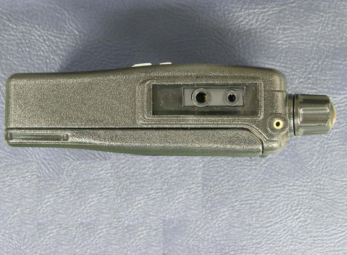
Click to zoom
Application Details
- Equipment Class
- TNF - Licensed Non-Broadcast Transmitter Held to Face
- Date of Grant
- Jan 18, 2007
- Application Purpose
- Original Equipment
- Date of Application
- Jan 18, 2007
- Equipment Note
- HANDHELD MARINE RADIO
- Frequency Range
- 156.02500000 - 157.42500000
- Company
- TTI Tech Co., Ltd.
- Country
- South Korea
Documents & Files
Document Text
Text extracted from the exhibit documents filed with the FCC. Open a document above to read the original.
Users Manual
MARINE TRANSCEIVER INSTRUCTION MANUAL www.ttikorea.co.kr Manufactured by TX-150M SCAN MENUD/T Thank you for purchasing this TTI radio. All our products are built to of fer excellent value by combining advanced features, great design and manufacturing quality. To ensure you are familiar with the operation and features of your radio, and in order to obtain the best performance, please read this manual carefully before operation. ENGLISH ENGLISH Caution ...................................................... 4 1. Radio Controls ........................................... 5 2. Equipment and Accessories Supplied ....... 6 3. Fitting the Battery pack .............................. 6 4. Battery Charging ....................................... 7 5. Radio Controls ........................................... 8 6. LCD Display ............................................ 10 7. Basic Radio Operation ............................. 11 8. Function(Menu) Mode ............................. 11 9. Radio Features Explained ....................... 12 Volume level .......................................12 Channels ........................................... 12 Power Hi / Low ................................. 12 Squelch Level Adjustment ................ 12 Monitor .............................................. 12 Keypad Lock ..................................... 13 Channel 16 ....................................... 13 Last Channel Memory (LCM) ........... 13 Dual Watch and Triple Watch Mode .. 13 Channel Scan ................................... 14 Priority Channel . ............................... 15 Key Beep . ......................................... 15 Roger Beep .......................................15 Call Tone .. ......................................... 16 Display & Keypad Backlight .............. 16 Battery Level ..................................... 16 Power Save ...................................... 16 10. Troubleshooting ....................................... 17 11. CE Declaration ......................................... 17 12. Safety Requirements ................................ 18 13. Technical Specifications ........................... 19 CONTENTS 4 TX-150M Caution ENGLISH IMPORTANT - READ ALL INSTRUCTIONS carefully and completely before operating your radio and retain this manual for future reference. NEVER connect the radio to a power source other than the supplied battery. This may damage your product. NEVER operate your radio with the antenna less than 5cm from exposed parts of the body. NEVER use the radio in or near a mining facility or other area which uses remotely triggered explosives or an area labelled "Blasting Area". NEVER use or charge your radio in a potentially explosive atmosphere. DO NOT place your radio in front of a vehicle airbag. DO NOT operate your radio on board an aircraft. DO NOT use your radio with a damaged antenna. DO NOT attempt to modify your radio in any way. ALWAYS charge your radio at normal room temperature. ALWAYS switch of f your radio where notices restrict the use of two-way radio or mobile telephones. ALWAYS replace the accessory jack cover (if applicable) when the jack is not in use. ONLY use TTI approved rechargeable batteries with the supplied charger. AVOID submerging your radio into water. It is not submersible. AVOID storing or charging your radio in direct sunlight. AVOID storing or using your radio where temperatures are below -20ºC or above +60ºC. 3 4 5 6 13 1 2 5 TX-150M 1 2 3 4 5 6 7 8 9 Strap Hole Antenna PTT Button Squelch & Monitor Button Keypad Lock Button Down Button Channel 16 Button Menu Button Microphone 10 11 12 13 14 15 16 17 Power On/Off & Volume Control Knob Jack Cover Lid Holder Accessory Jack LCD Display Up Button Scan Button Dual/Triple Watch Speaker ENGLISH 1. Radio Controls 17 10 11 12 SCAN MENUD/T 7 15 16 9 8 14 Fitting 1. Ensure that your radio is switched off. 2. Align the bottom of the battery pack with the securing slots at the back of the radio. 3. Press the top of the battery into the back of the radio until it 'clicks' home. Removal 1. Ensure that your radio is switched off. 2. Press down on the battery release catch and separate the battery pack from the radio. 6 TX-150M Fitting Removal 1. TX-150M radio 2. Replaceable Antenna 3. Li-Ion Battery pack (730mAh) 4. Charging Cradle 5. Power Adaptor 6. Carry Case 7. Instruction Manual 1 unit 1 unit 1 unit 1 unit 1 unit 1 unit 1 unit ENGLISH 2. Equipment and Accessories Supplied 3. Fitting the Battery pack 7 TX-150M LED ENGLISH To charge your radio, carefully follow these instructions: 1. Connect the power adaptor to the main power supply and connect the adaptor power plug to the charging cradle. 2. Disconnect any radio accessories and ensure the radio is switched off. 3. Insert the radio into the charging cradle until it 'clicks' home. The charger LED will glow red and charging will start. If the charger LED blinks red and green or the charger LED does not light, re-insert the radio into the charging cradle. 4. The battery charging time is typically 12 to 15 hours. When the battery is fully charged the charger LED will turn green. 4. Battery Charging Charge Cradle Adaptor Power Plug Power Adaptor : - Input: 230VAC - Output: 9VDC SCAN MENUD/T SCAN MENUD/T 8 TX-150M 1. Power On/Off/Volume control 5. DOWN button 6. UP button Turn the knob clockwise to switch on and increase the volume and counter-clockwise to decrease the volume and switch of f the radio. The radio will emit a confirmation tone when it switches on. 2. Push-To-Talk (PTT) button Press and hold this button to speak (transmit) and release the button to hear (receive) messages. You can only communicate with other marine band radios when the channel and privacy code settings are the same as yours. Double click this PTT button quickly twice to send call(page) tone. Pressing this button will decrease the channel number. In some modes this button is used to adjust the function setting. Pressing this button will increase t…
Text truncated - open the document above for the full version.
Cover Letter(s)
tti.... TTI Tech Co., Ltd. TTI House, 163-4, Poi-Dong Kangnam-Ku, Seoul, Korea 135-260 (T) +82 2 518 2417/8 (F) +82 2 518 2419 November 14, 2006 Federal Communications Commission Authorization and Evaluation Division Re : Confidentiality Request - FCC ID : PDHTX150M To whom it may concern : Pursuant to Sections 0.457 and 0.459 of the Commission’s Rules, we, TTI Tech Co., Ltd., hereby request the confidential treatment of the information accompanying the applications for certification of FCC ID : PDHTX150M as outlined below : ° Block Diagram ° Schematic Diagram(s) ° Operational Description The above materials contain trade secrets and proprietary information not customarily released to the public. The public disclosure of these materials may be harmful to the applicant and provide unjustified benefits to its competitors. The applicant understands that pursuant to Section 0.457 of the Rules, the disclosure of this application and all accompanying documentation will not be made before the date of the Grant for this application. Thank you. Sincerely, H. J. Lee / Senior Manager Overseas Sales - TTI
ID Label/Location Info
* Location * 2:1 2:1 * NOTE 1. TEXT : WHITE 2. BACKGROUND : BLACK 3. MATERIAL : POLYESTER T=0.2 31.0 14.0 31.0 14.0 DATE : JAN 19 , 2007 (REV. 00) PDHTX150M FCC ID LABEL FCC ID : PDHTX150M TRADE NAME : FM TRANSCEIVER MODEL NO. : TX-150M FCC ID : PDHTX150M TRADE NAME : FM TRANSCEIVER MODEL NO. : TX-150M THE FCC ID LABEL CAN BE FOUND ON THE INSIDE OF THE BATTERY COMPARTMENT WHEN THE BATTERY PACK IS REMOVED. FCC ID : PDHTX150M TRADE NAME : FM TRANSCEIVER MODEL NO. : TX-150M 1. LABEL IN THE BATTERY COMPARTMENT : 2. STATEMENT ON THE GIFT BOX :
Parts List/Tune Up Info
TX-150M ALIGNMENT PROCEDURE Page 1 1. REFERENCE TEST EQUIPMENT A. HP8921A Cell site test set or HP8920A, B Communication Test Set with Spectrum Analyzer option. B. Fluke 187 Digital Voltmeter C. HP E3615A Power supply 2. TEST POINT A. ANTENNA : Test point is not prepared. Use SMA antenna connector. B. VCO reference voltage : Test point VCO-B is prepared. C. RX audio output : Test point J4 is prepared. D. TX Mic. Input : Test point J1 is prepared. E. Battery Vcc : Test point BAT-B is prepared. F. Up Key : Test point UP(SW2) is prepared. G. Down Key : Test point DW(SW1) is prepared. H. Menu Key : Test point Menu(SW4) is prepared. I. Scan Key : Test point SCAN(SW6) is prepared. J. PTT Key : Test point PTT(SW7) is prepared. K. CH16 Key : Test point CH16(SW3) is prepared. L. DW/TW Key : Test point DW/TW(SW5) is prepared. M. Lock Key : Test point Lock(SW9) is prepared. N. SQL/Monitor Key : Test point SQL(SW8) is prepared. Note. : All key can be activated when connect with ground. 3. VCO ALIGNMENT A. Set unit to Channel 1 and connect a voltmeter to VCO-B (VCO PD). B. Press & hold PTT. C. Align CT1 until the voltmeter reads 3.0V. D. Release PTT button so units is in receiving mode and monitor the voltage on VCO-B. The voltage should be in the range 1.1Vds +/-0.3Vdc. E. Set unit to channel 88. F. Press & hold the PTT switch and observe the voltage on VCO-B . The voltage should be in the range 3.5Vdc +/-0.5Vdc. G. Release PTT and observe the voltage on VCO-B. The voltage should be read 3.0Vdc +/- 0.5Vdc. Note : VCO shield-can should be soldered after VCO alignment is finished. 4. TRANSMITTER FREQUENCY ALIGNMENT A. While Press & hold the PTT, Menu and Down buttons, the knob clockwise to switch on the radio.. B. Align Up or Down button such that the output frequency is equal to the channel frequency with a maximum error of +/- 200 Hz. TX-150M ALIGNMENT PROCEDURE Page 2 TRANSMITTER OUTPUT POWER CONFIRMATION A. Set unit to channel 1 and power Hi mode. B. Press & hold the PTT button. C. Transmit power should normally be between 3.5W to 5.0W. D. Set unit to channel 1 and power Low mode. E. Press & hold the PTT button. F. Transmit power should normally be between 0.8W to 1.3W. 5. TRANSMITTER DEVIATION ALIGNMENT A. Connect an audio generator (600 ohms) to the ear jack. The audio frequency should be set at 1KHz with a level of 200mV RMS. B. Connect an FM deviation meter (communications test set) to Antenna SMA connector. Set the monitor to read peak to peak divided by two [(pk-pk)/2] deviation. Set filter of equipment from 25Hz to 15KHz. C. Press & hold the PTT button. D. Align RV2 for +/- 4.4 kHz deviation (+/-0.2KHz). RV201 is located at the left side of con5 on the RF PCB. E. Decrease audio generator level until deviation reads +/- 3.0 kHz (approximately 6mV) and record generator level. Level should be between 3 mV and 10 mV. F. Confirm that transmit audio distortion is less than 5%. 6. RECEIVER ALIGNMENT A. Set the output level of the RF signal generator for -47dBm. The generator should be set for 3.0 kHz deviation at 1 kHz audio. B.Turn the knob clockwise to switch on and increase the volume of radio. C. Connect Audio analyzer to SPKOUT. D. Set equipment filter 25Hz to 15KHz. E. Align L407 to get a maximum output level & a minimum distortion and confirm that Rx audio distortion is less than 3%. F. Confirm that Rx Sensitivity is less than –119dBm (nominally –122dBm) by reducing the output level of the RF signal generator until a 12 dB SINAD reading is achieved. H. Set SSG output level until 9dB sinad sensitivity and confirm until the unit is un-squelched. I. Set signal generator level to –47dBm. J. With 3.0KHz deviation at 1KHz modulation, set volume for maximum audio. Audio level should be on over than 2.5Vrms. 7. BATTERY INDICATOR CONFIRMATION A. Set unit to receiving mode. Don’t set transmitter mode.. B. Set power supply voltage to 7.4 Vdc. C. Decrease power supply voltage until low battery icon blinks. 8. POWER OFF CURRENT CONSUMPTION A. Set power supply voltage to 7.4 Vdc and connect to unit. B. Confirm current. It must be less than 100uA.
Test Report
THRU & Engineering. RM1105,11FL, ACE TECHNO TOWER 197-22,GURO-DONG GURO-GU SEOUL KOREA 81221095059F81221095056 email [email protected] APPLICANT : TTI Tech Co., Ltd. FCC ID : PDHTX150M REPORT: 2645AUT6 TestReport2 Pages: 1of 5 2.1047 (a) (b) Modulation characteristics : AUDIO FREQUENCY RESPONSE The audio frequency response was measured in ac- cordance with TIA/EIA Specification 603. The audio frequency response curve is shown on the page. The audio signal was fed into a dummy microphone Circuit and into the microphone connector. The Input required to produce 20 percent modulation Level was measured. See plot below. AUDIO FRQUENCY RESPONSE PLOT GOES HERE AUDIO FREQUENCY RESPONSE -35 -30 -25 -20 -15 -10 -5 0 5 10 0.10.20.40.60.811.522.533.544.55 FREQ UEN CY KHz dB THRU & Engineering. RM1105,11FL, ACE TECHNO TOWER 197-22,GURO-DONG GURO-GU SEOUL KOREA 81221095059F81221095056 email [email protected] APPLICANT : TTI Tech Co., Ltd. FCC ID : PDHTX150M REPORT: 2645AUT6 TestReport2 Pages: 2 of 5 2.1047 (b) Audio input versus modulation The audio input level needed for a particular per- percentage of modulation was measured in accor – dance with TIA/EIA Specification 603. The audio input curves versus modulation are on the following pages. Curves are provided for audio input frequent- cies of 300, 1000, and 3000 Hz. MODULATION LIMITING 300Hz 0.000 0.500 1.000 1.500 2.000 2.500 3.000 3.500 4.000 4.500 5.000 13579 1525354555657585 100200300400 mV Deviation KHz MODULATION LIMITING 1000Hz 0.000 0.500 1.000 1.500 2.000 2.500 3.000 3.500 4.000 4.500 5.000 1 2 3 4 5 6 7 8 9 101520253035404550556065 mV Deviation KHz THRU & Engineering. RM1105,11FL, ACE TECHNO TOWER 197-22,GURO-DONG GURO-GU SEOUL KOREA 81221095059F81221095056 email [email protected] APPLICANT : TTI Tech Co., Ltd. FCC ID : PDHTX150M REPORT: 2645AUT6 TestReport2 Pages: 3 of 5 MODULATION LIMITING 2500Hz 0.000 0.500 1.000 1.500 2.000 2.500 3.000 3.500 4.000 4.500 5.000 1 2 3 4 5 6 7 8 9 10 1520 2530 3540 4550 5560 65 mV Deviation KHz MODULATION LIMITING 3000Hz 0.000 0.500 1.000 1.500 2.000 2.500 3.000 3.500 4.000 4.500 5.000 1 2 3 4 5 6 7 8 9 101520253035404550556065 mV Deviation KHz THRU & Engineering. RM1105,11FL, ACE TECHNO TOWER 197-22,GURO-DONG GURO-GU SEOUL KOREA 81221095059F81221095056 email [email protected] APPLICANT : TTI Tech Co., Ltd. FCC ID : PDHTX150M REPORT: 2645AUT6 TestReport2 Pages: 4 of 5 AUDIO LOW PASS FILTER GRAPH 95.637 Post Limiter Filter Each, except a Mobile station transmitter with a power of 2.5Watts or less, must be equipped with an audio low pass filter. At any frequency between 3 & 20 kHz the filter must have an attenuation of 60log (f/3) greater than the attenuation at 1KHz. See below. THRU & Engineering. RM1105,11FL, ACE TECHNO TOWER 197-22,GURO-DONG GURO-GU SEOUL KOREA 81221095059F81221095056 email [email protected] APPLICANT : TTI Tech Co., Ltd. FCC ID : PDHTX150M REPORT: 2645AUT6 TestReport2 Pages: 5 of 5 2.1055(a)(2) Frequency stability 80.209(a) Temperature and voltage tests were performed to verify that the frequency remains within the 0.0010%, 10 ppm specification limit. The test was conducted as follows: The transmitter was placed in the temperature chamber at 25ºC and allowed to stabilize for one hour. The transmitter was keyed ON for one minute during which four frequency readings were recorded at 15 second intervals. The worse case number was taken for temperature plotting. The assigned channel frequency was considered to be the reference frequency. The temperature was then reduced to –20ºC after which the transmitter was again allowed to stabilize for one hour. The transmitter was keyed ON for one minute, and again frequency readings were noted at 15 second intervals. The worse case number was recorded for temperature plotting. This procedure was repeated in 10 degree increments up to + 50ºC. Readings were also taken at minus 15% of the battery voltage, which we estimate to be the battery endpoint. MEASUREMENT DATA: Assigned Frequency (Ref. Frequency): 156.70000 TEMPERATURE FREQUENCY(MHz) ppm LIMIT(ppm) REFERENCE 156.70000 10.0 -20 156.70040 2.55 10.0 -10 156.70010 0.64 10.0 0 156.70019 1.21 10.0 10 156.70017 1.08 10.0 20 156.69981 -1.21 10.0 30 156.69988 -0.77 10.0 40 156.69984 -1.02 10.0 50 156.69989 -0.70 10.0 End of Voltage 4.5V 156.69940 -3.83 10.0
Test Report
TIMCO ENGINEERING INC. 849 NW State Road 45 Newberry, Florida 32669 http://www.timcoengr.com 888.472.2424 F 352.472.2030 email: [email protected] APPLICANT: TTI TECH CO., LTD. FCC ID: PDHTX150M REPORT #:V:\T\TTI_PDH\2645AUT6\Extra2645AUT6\2645AUT6TestReport.doc COVER SHEET Test Report Product Name: HANDHELD MARINE TRANSCEIVER FCC ID: PDHTX150M Applicant: TTI TECH CO., LTD. TTI HOUSE, 163-4, POI-DONG KANGNAM-KU, SEOUL, KOREA 135-260 Date Receipt: 9/18/2006 Date Tested: 9/21/2006 TIMCO ENGINEERING INC. 849 NW State Road 45 Newberry, Florida 32669 http://www.timcoengr.com 888.472.2424 F 352.472.2030 email: [email protected] APPLICANT: TTI TECH CO., LTD. FCC ID: PDHTX150M REPORT #:V:\T\TTI_PDH\2645AUT6\Extra2645AUT6\2645AUT6TestReport.doc TABLE OF CONTENTS TABLE OF CONTENTS LIST APPLICANT: TTI TECH CO., LTD. FCC ID: PDHTX150M TEST REPORT: PAGE 1............GENERAL INFORMATION & TECHNICAL DESCRIPTION PAGE 2............TECHNICAL DESCRIPTION CONTINUED RF POWER OUTPUT PAGE 3............TECHNICAL DATA PAGE 4............VOICE MODULATION CHARACTERISITICS AUDIO FREQUENCY RESPONSE AUDIO LOW PASS FILTER PAGE 5............OCCUPIED BANDWIDTH PAGE 6............OCCUPIED BANDWIDTH PLOT PAGE 7............SPURIOUS EMISSIONS AT ANTENNA TERMINALS PAGE 8............METHOD OF MEASURING CONDUCTED SPURIOUS EMISS PAGE 9............FIELD STRENGTH OF SPURIOUS EMISSIONS PAGE 10...........METHOD OF MEASURING RADIATED SPURIOUS EMISSIONS PAGE 11...........FREQUENCY STABILITY PAGE 12...........LIST OF TEST EQUIPMENT EXHIBITS INCLUDING: CONFIDENTIALITY REQUEST LETTER BLOCK DIAGRAM SCHEMATIC PARTS LIST USERS MANUAL LABEL SAMPLE LABEL LOCATION EXTERNAL PHOTOGRAPHS INTERNAL PHOTOGRAPHS OPERATIONAL DESCRIPTION TUNING PROCEDURE TEST SET UP PHOTOGRAPHS TIMCO ENGINEERING INC. 849 NW State Road 45 Newberry, Florida 32669 http://www.timcoengr.com 888.472.2424 F 352.472.2030 email: [email protected] APPLICANT: TTI TECH CO., LTD. FCC ID: PDHTX150M REPORT #:V:\T\TTI_PDH\2645AUT6\Extra2645AUT6\2645AUT6TestReport.doc Page 1 of 12 GENERAL_INFORMATION 2.1033(c) TTI TECH CO., LTD. will sell the FCC ID: PDHTX150M VHF Marine transmitter in quantity, for use under FCC RULES PART 80. 2.1033(c) TECHNICAL_DESCRIPTION (4) Type of Emission: 16K0F3E Bn = 2M + 2DK M = 3000 D = 5.0 (Peak Deviation) K = 1 Bn = 2(3.0K) + 2(5.0K)(1) = 6.0K + 10.0 = 16.0K 80.205 (a) ALLOWED AUTHORIZED BANDWIDTH = 20.00 kHz. 2.1033(c)(6) Frequency Range: 156.025 – 157.425 MHz 2.1033(c)(7) Power Range and Controls: There is a user Power switch for High/Low Power. Maximum Output Power Rating: High 5.5 Watts, Low 1.1 Watt into a 50 ohm resistive load. 2.1033(c)(8) DC Voltages and Current into Final Amplifier: POWER INPUT FINAL AMPLIFIER ONLY High Low Vce = 7.4 Volts Vce = 7.4 VDC Ice = 1.4 A Ice = 0.7 A Pin = 10.4 Watts Pin = 5.18 Watts Function of each electron tube or semiconductor device or other active circuit device is included as an exhibit. TIMCO ENGINEERING INC. 849 NW State Road 45 Newberry, Florida 32669 http://www.timcoengr.com 888.472.2424 F 352.472.2030 email: [email protected] APPLICANT: TTI TECH CO., LTD. FCC ID: PDHTX150M REPORT #:V:\T\TTI_PDH\2645AUT6\Extra2645AUT6\2645AUT6TestReport.doc Page 2 of 12 2.1033(c)(9) Complete Circuit Diagrams: The circuit diagrams and block diagrams are included. 2.1033(c)(10) Instruction book. The instruction manual is included. 2.1033(c)(11) Tune-up procedure. The tune-up procedure is included. Description of all circuitry and devices provided for determining and stabilizing frequency is included in the circuit description 2.1033(c)(11) Digital modulation. This unit does NOT use digital modulation. The data required by 2.1046 through 2.1055 is submitted below. 2.1046(a) RF_power_output . 80.215 (e)(1) RF power is measured by connecting a 50 ohm, re- sistive wattmeter to the RF output connector. With a nominal battery voltage, and the transmitter properly adjusted the RF output measures: OUTPUT POWER: HIGH: 5.5 W CONDUCTED LOW: 1.1 W CONDUCTED METHOD OF MEASURING RF POWER OUTPUT Transmitter 50 ohm under test Resistive Wattmeter Power Supply TIMCO ENGINEERING INC. 849 NW State Road 45 Newberry, Florida 32669 http://www.timcoengr.com 888.472.2424 F 352.472.2030 email: [email protected] APPLICANT: TTI TECH CO., LTD. FCC ID: PDHTX150M REPORT #:V:\T\TTI_PDH\2645AUT6\Extra2645AUT6\2645AUT6TestReport.doc Page 3 of 12 TECHNICAL DATA: 80.203 (b) External Controls: The transmitter is capable of changing frequency between 156.025 – 157.425 MHz by external control. The available channels are shown in the User Manual description Channel List. These channels are preprogrammed by the manufacturer and change of frequency is inaccessible to the station operator. TIMCO ENGINEERING INC. 849 NW State Road 45 Newberry, Florida 32669 http://www.timcoengr.com 888.472.2424 F 352.472.2030 email: [email protected] APPLICANT: TTI TECH CO., LTD. FCC ID: PDHTX150M REPORT #:V:\T\TTI_PDH\2645AUT6\Extra2645AUT6\2645AUT6TestReport.doc Page 4 of 12 2.1047(a) Voice Modulation_characteristics: REFER TO 2645AUT6 TESTREPORT2 2.1047(a) AUDIO_LOW_PASS_FILTER REFER TO 2645AUT6 TESTREPORT2 2.1047(b) Audio_input_versus_modulation 80.213 (d) A plot of the audio input versus deviation is shown in the following plot. REFER TO 2645AUT6 TESTREPORT2 TIMCO ENGINEERING INC. 849 NW State Road 45 Newberry, Florida 32669 http://www.timcoengr.com 888.472.2424 F 352.472.2030 email: [email protected] APPLICANT: TTI TECH CO., LTD. FCC ID: PDHTX150M REPORT #:V:\T\TTI_PDH\2645AUT6\Extra2645AUT6\2645AUT6TestReport.doc Page 5 of 12 2.1049(c) Occupied bandwidth: 80.213 (b) Data in the plots shows that on any frequency removed from the assigned frequency by more than 50%, but not more than 100%: At least 25dB. On any frequency removed from the assigned frequency by more than 100%, but not more than 250%: At least 35dB. On any frequency removed from the assigned frequency by more than 250%, of the authorized bandwidth: At least 43 + log(P)dB. Radiotelephone transmitter with modulation limite…
Text truncated - open the document above for the full version.
Contact Information
Applicant
J. N. LEE(Manager)
Test Firm
Timco Engineering, Inc.Sid Sanders
Technical Specifications
| # | Rule Parts | Frequency Range | Power Output | Emission | Tolerance |
|---|---|---|---|---|---|
| 2 | 8 | 156.025 MHz - 157.425 MHz | 1.1 W | 16K0F3E | 10 ppm |
Other Applications from TTI Tech Co., Ltd.
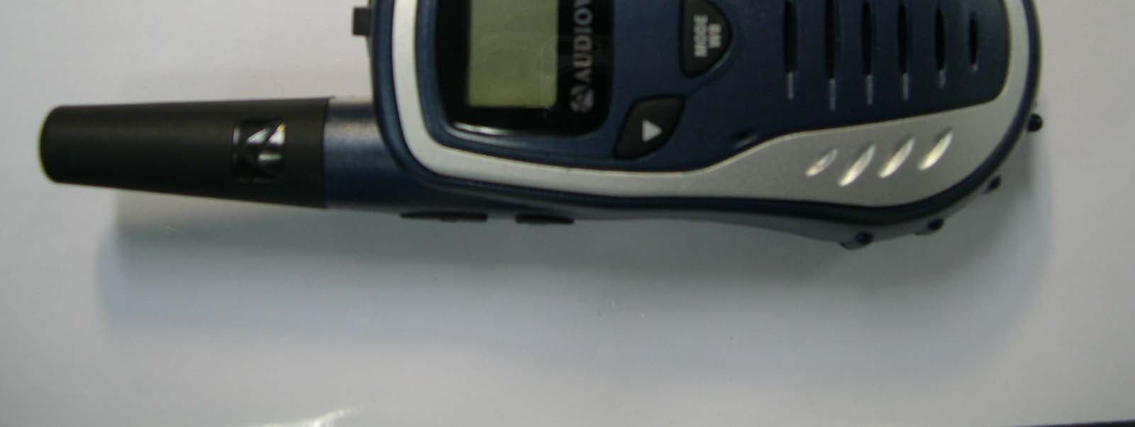
PDHGMRS200
Jul 05, 2005FRS/GMRS COMBINATION
Equipment Class
FRF - Part 95 Family Radio Face Held Transmitter
PDHGMRS1202
Feb 06, 2005FRS/ GMRS Combination
Equipment Class
FRF - Part 95 Family Radio Face Held Transmitter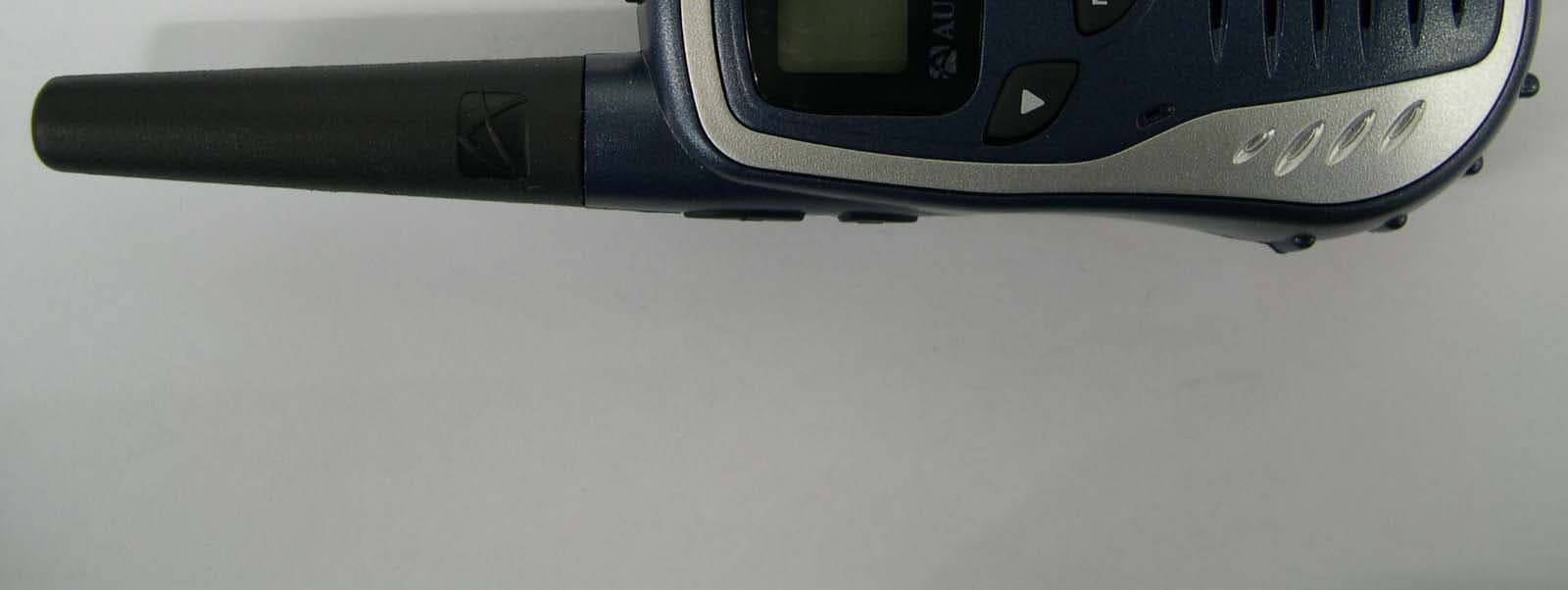
PDHGMRS602
Feb 06, 2005FRS/ GMRS Combination
Equipment Class
FRF - Part 95 Family Radio Face Held Transmitter
PDHGMRS500SLK
Apr 06, 2004GMRS/FRS Combination
Equipment Class
FRF - Part 95 Family Radio Face Held Transmitter
PDHGMRS9010
Feb 05, 2004FRS/GMRS COMBINATION
Equipment Class
FRF - Part 95 Family Radio Face Held Transmitter