PDLAV420W42" TFT LCD TV
ATEC Co., Ltd.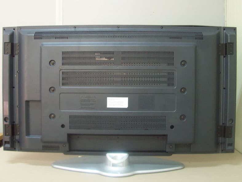
Click to zoom
Application Details
- Equipment Class
- JBP - Part 15 Class B Computing Device Peripheral
- Date of Grant
- May 24, 2005
- Application Purpose
- Original Equipment
- Date of Application
- May 24, 2005
- Equipment Note
- 42" TFT LCD TV
- Company
- ATEC Co., Ltd.
- Country
- South Korea
Documents & Files
Document Text
Text extracted from the exhibit documents filed with the FCC. Open a document above to read the original.
Users Manual
1 1. Read these instructions. 2. Keep these instructions. 3. Heed all warnings. 4. Follow all instructions. 5. Do not use this apparatus near water. 6. Clean only with a dry cloth. 7. Do not block any ventilation openings. Install in accordance with the manufacturer’s instructions. 8. Do not install near any heat source such as radiators, stoves, or other apparatus (including amplifiers) that produce heat. 9. Do not allow the safety purpose of the polarized or grounding-type plug to be circumvented. A polarized plug has two blades one wider than the other. A grounding-type plug has two blades and a third grounding prong. The wide blade and third prong are provided for your safety. If the plug provided does not fit into your outlet, consult an electrician for replacement of the obsolete outlet. 10. Protect the power cord from being walked on or constricted particularly near the plug, by waste bins, and at the point where it exits from the apparatus. 11. Only use attachments/accessories specified by the manufacturer. 12. Use only with the cart, stand, tripod, bracket, or table specified by the manufacturer, or sold with the apparatus. When a cart is used, use caution when moving the cart/apparatus combination to avoid injury from overturning. 13. Unplug this apparatus during electrical storms or when unused for long periods of time. 14. Refer all servicing to qualified service personnel. Servicing is required when the apparatus has been damaged in any way, such as when the power-supply cord or plug is damaged, when liquid has been spilled on it, when it does not operate normally, or has been dropped. 15. The apparatus should not be exposed to dripping or splashing of liquids, and objects filled with liquid, such as vases, should not be placed on the apparatus. Important Safety Instruction 2 Shock Hazard Marking and Associated Graphic Symbols Explanation of Safety Related Symbols WARNING – To Reduce The Risk Of Fire Or Electric Shock, Do Not Expose This Apparatus To Rain Or Moisture. This symbol is intended to alert the user to the presence of uninsulated “dangerous voltage” within the product’s casing that may be of sufficient magnitude to constitute a risk of electric shock. RISK OF ELECTRIC SHOCK DO NOT OPEN CAUTION: TO REDUCE THE RISK OF ELECTRIC SHOCK, DO NOT REMOVE COVER (OR BACK). NO USER SERVICEABLE PARTS INSIDE. REFER SERVICING TO QUALIFIED SERVICE PERSONNEL. This symbol is intended to alert the user to the presence of important operating and maintenance(servicing) instructions in the literature accompanying the appliance. RISK OF ELECTRIC SHOCK DO NOT OPEN CAUTION CAUTION Important Safety Instruction 3 General safety precautions Never touch the power plug with wet hands. An electric shock may occur. Don’t plug more than one appliance into the same power outlet. An electric shock or fire may occur. Insert the plug fully so that the power supply unit is connected securely. Unsafe power connection may cause a fire. Grasp the power plug at the base to remove it from the wall, and pull firmly but gently. If you jerk the cord, the wire may be break, causing ignition or heat generation. Select a cool, dry area and protect the LCD display from extremes of temperature, humidity, dust and smoke. Electric shock, fire or failure may occur. Place the apparatus at a proper distance (over 10 cm) away from the wall for sufficient ventilation. A fire may result from an increase in internal temperature. Place the monitor in a well-ventilated room. A fire may result from an increase in internal temperature. Do not touch the antenna when ti is snowing or, raining, or during electrical storm. Electric shock may result. There may be a danger of electric shock when installing the outdoor antenna; please consult a specialist firm. Electric shock may result. Important Safety Instruction Position the outdoor antenna line in such a way as to prevent rain water flowing into the parts indoors. A fire or electric shock may be caused if rainwater is allowed to get into the LCD display. Never disassemble and repair this apparatus yourself; use trained repair engineers. A fire or electric shock may result. If repair or adjustment is reguired, please contact the appropriate sales agency or customer advisor. Don’t insert metal objects (such as coins, hair pins or ironware) or flammable items (such as paper or matches) into the apparatus. A fire or electric shock may result. Stop using the apparatus in case of smoke or abnormal odors. Immediately turn off the power, pull the power cord out of the wall and then contact your service center. Continued use in these circumstances may cause a fire or electric shock. Please prevent children from tampering with or swallowing a remote control dry cell. Keep dry cells out of children’s reach. If a child swallows one, please consult a doctor immediately. Place on a stable and secure surface. If the monitor falls or is dislodged, it may cause an injury. Turn off the apparatus and disconnect all cables from the monitor before moving the apparatus. Do not subject the apparatus to shock when moving. 4 Important Safety Instruction If installing or moving the LCD TV after opening the LCD TV box, ensure that two persons hold each side of the unit for moving it to the installation site. This is to avoid potential hazards to the LCD TV as well as to the people moving the unit. Carrying an LCD TV by only one person places intense stress on the back, possibly resulting in back injuries. The unit could also be dropped on the floor, which could break the cradle or cause other injuries. Don’t put pressure on the panel or scratch the surface with your hands or a sharp item such as a nail or pen. Damage or failure of the panel may result. Keep an appropriate distance from the product. If you watch the product continually at too short a range, your eyesight may be damaged. When replacing dry cells, make sure to align the polarity (+, -) correctly. Please use only designated standard products. …
Text truncated - open the document above for the full version.
Users Manual
Watching TV To configure the menu To Configure TV Channels To Select TV/External Input Adjusting the Picture Adjusting the Sound Configuring the PIP/POP/PBP Functions To Configure the SET UP External Control Device Setup 2-2 Watching TV Check the antenna connection. (For more information on connection, see ‘1.4 Connecting the LCD TV and Peripheral Devices’.) 1 Press the power button on the rear panel of the LCD TV. 2 Press the <POWER> button on the remote control. 3 Press the <TV/AV> button on the remote control, and press the number button to select a channel (For example, if selecting channel no. 99, press the 9 button twice on the remote control). 4 Press the < > button to adjust the volume. 5 2-3 Watching TV Using the LCD TV NOTE To mute the LCD TV sound Press the <MUTE> button on the remote control once to mute the LCD TV sound. Press the button once again to turn the sound back on. To completely turn off the LCD TV power. Press the <POWER> button on the remote control. The LCD TV will be turned off and remain in standby mode. Press the power button on the rear panel of the LCD TV (or unplug the power cord from the wall outlet). 2-4 To configure the menu To configure the LCD TV functions, press the [MENU] button. Knowing the method for configuring the menu will make using the LCD TV much easier. Menu Settings Press the power button on the rear panel of the LCD TV, and press the <POWER> button on the remote control. 1 Press the <MENU> button on the remote control. Press the < > button on the remote control to navigate to different menus. 2 <PICTURE> <SOUND><PIP/POP/PBP> <SET UP><CHANNEL> 2-5 To configure the menu Using the LCD TV Press the <OK> button or the < > button on the remote control to select the menu to configure. Submenus will be available for each selection. 3 In the submenus, use the < > button on the remote control to navigate to different items. Use the < > button to make adjustments. When selecting PIP Source, use the < > button to make adjustments, and then press the <OK> button on the remote control to make a selection (Select the ‘User’ item under the 'PSM’ submenu). 4 Using the LCD TV 2-6 To configure the menu Use the < > button and the < > button on the remote control to adjust the settings for different items. (For example, adjustment can be made of items such as Brightness, Contrast, Color, Sharpness, and Tint.) 5 When adjustments are complete, press the <OK> button once to close the adjustment screen. Press the <MENU> button once again to close the ‘Menu’ screen. 6 NOTE To configure the menu without using the remote controller Press the <MENU> button located at the bottom of the LCD TV. Press the <CH /> buttons to navigate to submenus. Press the <VOL </ > buttons to adjust each item. If ‘Menu for Local Key’ is on, the <SOURCE> button is used as the <OK> button. When adjustments have been completed, press the <MENU> button to close the ‘Menu’ screen. 2-7 To configure the menu Using the LCD TV Main Menu PICTURE PSM (Select Screen View) Dynamic Standard Mild Game User Vivid Picture Appearance Standard Picture Appearance Softer Picture Appearance Select when playing video games on LCD TV Brightness : Adjust brightness. (Brightness means the brightness of the screen.) Contrast : Adjust contrast. (Contrast means the difference in brightness between an object and its background.) Colour : Adjust color (RGB).(Adjusting the color to make it look more natural.) Sharpness : Adjust sharpness.(Sharpness means the sharpness of the object's profile.) Tint : Adjust color intensity.(Color intensity indicates color depth.) SOUND Effect Surround AVL Balance Flat Music Movie Speech User Off Normal Spatial On/Off -10 ~ 10 Standard factory settings. When watching music video or concerts. When watching movies. When watching a show that is mostly dialogue. Bass : Adjust bass. Treble : Adjust treble. Surround Output Off Optimal Surround for Output Condition Enhanced Surround AVL Function On/Off Adjust balance between the left & right speakers. Sub Menu 1 Sub Menu 2 Sub Menu 3 TV Menu Categories and Items The Main Menu contains 5 categories, which in turn contain submenus and option items: Using the LCD TV 2-8 To configure the menu Main Menu SET UP Language Transparency ARC ISM Method Set ID Factory Reset Timer Caption Parental English, Deutsch, Français, Español, Italiano, Korean (Menu Screen Display Language Selection) 0~10 16:9, 14:9, 4:3 Normal Orbit White 0~99 Off Clock Off Timer On Timer Auto Off TEXT 1~4 Off CC1~4 Lock On/Off MPAA TV Guidelines Set Password Adjusts the image transparency Screen Aspect Selection Normal screen Moves the screen up, down, left and right in small increments to prevent overheating of the panel during prolonged use. Sets the whole screen to white. Set ID Selection Selects the factory default. AM, PM AM, PM, On/Off AM, PM, On/Off CHANNEL Volume On/Off Text function support Caption function Off (when the subtitle function is provided) Closed Captioning function support Parental function On/Off MPAA(Motion Picture Association of America) Guideline setup available TV Guidelines function support Password setup available Sub Menu 1 Sub Menu 2 Sub Menu 3Description Time Selection TV Off Time Selection TV On Time Selection CATV/Air 0~100 TV Off Auto Function Selection PIP/POP/PBP On/OffOff PIP POP PBP1~2 PIP/POP/PBP Function Off Source Swap PIP Size PIP Position Source Swap Source Swap TV, AV1~AV3, Component1~2, RGB, DVI To Set Small, Large PIP Screen Position Selection TV, AV1~AV3, Component1~2, To Set TV, AV1~AV3, Component1~2, RGB, DVI To Set 2-9 To configure the menu Using the LCD TV Main Menu CHANNEL Air/CATV Auto CH Progress Channel Add/Del Channel Fine Tune Scan by broadcasting method Automatic channel scan Scans the TV channels and registers the channels on air Saves the selected channels Manually fine tune the channels if the channel reception is not good Sub Menu 1 Sub Menu 2 2-10 To Configure TV Channels To watch TV with the LCD TV, configure the cha…
Text truncated - open the document above for the full version.
Users Manual
Initial PC Mode Settings PC Menu Components Main Menu Settings 3-2 Initial PC Mode Settings To use the PC mode, set the resolution on the PC to 1280 x 768 @ 60Hz / 1360 x 768 @ 60Hz, and connect it to the LCD TV (supports up to 1600 x 1200 @ 60Hz/1280 x 1024 @ 85). Connect the LCD TV and the PC, and press the <POWER> button. 1 Press the <SOURCE> button on the remote control. The ‘MAIN SOURCE’ screen will be displayed. 2 Check the type of cable that connects the LCD TV and the PC. Press the < > button on the remote control to navigate to RGB (or DVI), and press the <OK> button. (or press the <PC> button on the remote control.) 3 The ‘PC’ screen will be displayed. 4 NOTE Highest resolution supported by the PC mode Main screen : 1600x1200 @ 60Hz/1280x1024 @ 85Hz Sub screen : 1280x768 @ 60Hz/1360x768 @ 60Hz 3-3 Initial PC Mode Settings PC Mode Environment Settings 3-4 PC Menu Components The Main menu has 5 categories, which contain submenus and option items. Main Menu PICTURE CSM Brightness Contrast Normal Cool Warm User Adjust the over-all brightness or darkness of the screen. Adjust the brightness and darkness between objects and back-grounds. Plain white. Bluish white. Reddish white. Controls color (Red, Green, Blue) of the display. SOUND Effect Surround AVL Balance Flat Music Movie Speech User Off Normal Spatial On/Off -10 ~ 10 Standard factory settings. When watching music video or concerts. When watching movies. When watching a show that is mostly dialogue. Bass : Adjusts bass Treble : Adjusts treble Surround Output Off Optimal Surround for Output Condition Enhanced Surround AVL Function On/Off Adjust balance between the left & right speakers. Sub Menu 1 Sub Menu 2 Sub Menu 3 Switch to the ‘PC’ mode and press the <MENU> button on the remote control. The ‘MAIN MENU’ screen will be displayed. 3-5 PC Menu Components PC Mode Environment Settings Main Menu SCREEN Auto configure H-Position V-Position Clock Phase To Start 0 ~ 100 0 ~ 100 0 ~ 100 0 ~ 255 Automatic adjustment of the screen/Auto in Progress Horizontal screen position adjustment Vertical screen position adjustment Picture quality adjustment by fine-tuning Screen phase adjustment (adjustment for screen noise, focus when letters appear to overlap each other, brightness, stability, etc.) Sub Menu 1 Sub Menu 2 Sub Menu 3Description PIP/POP/PBP On/OffOff PIP POP PBP1~2 PIP/POP/PBP Function Off Source Swap PIP Size PIP Position Source Swap Source Swap TV, AV1~AV3, Component1~2, RGB, DVI To Set Small, Large PIP Screen Position Selection TV, AV1~AV3, Component1~2, RGB, DVI To Set TV, AV1~AV3, Component1~2, RGB, DVI To Set SET UP Language Transparency ARC ISM Method Set ID Factory Reset Timer English, Deutsch, Français, Español, Italiano, Korean (Menu Screen Display Language Selection) 0~10 16:9, 14:9, 4:3 Normal Orbit White 0~99 Off Clock Off Timer On Timer Auto Off Adjusts the image transparency Screen Aspect Selection Normal screen Moves the screen up, down, left and right in small increments to prevent overheating of the panel during prolonged use. Sets the whole screen to white. Set ID Selection Selects the factory default. AM, PM AM, PM, On/Off AM, PM, On/Off CHANNEL Volume On/Off Time Selection TV Off Time Selection TV On Time Selection CATV/Air 0~100 TV Off Auto Function Selection 3-6 Main Menu Settings PICTURE Menu Settings Switch to the ‘PC’ mode, press the <MENU> button on the remote control, and then press the <OK> button on the remote control. 1 Press the <OK> button or the < > button on the remote control. The menu will be selected, and the submenus can be navigated. Select the ‘CSM (Color Standard Mode)’ submenu and press the < > button on the remote control to select the option item (select option items like ‘Normal, Cool, User, Warm’ and so on in the ‘CSM’ submenu). 2 3-7 Main Menu Settings PC Mode Environment Settings When selection is complete, press the <OK> button on the remote control. 3 Press the < > button on the remote control to navigate to the ‘Brightness, Contrast’ submenu in order to adjust brightness and contrast. 4 When adjustment is complete, press the <OK> button on the remote control, and press the <MENU> button on the remote control once again to close the ‘Menu’ screen. 5 NOTE S To configure the menu without the remote controller Press the <MENU> button located at the bottom of the LCD TV. Press the <CH /> buttons to navigate to submenus. Press the <VOL </ > buttons to adjust each item. If ‘Menu for Local Key’ is on, the <SOURCE> button is used as the <OK> button. When adjustments are complete, press the <MENU> button to close the ‘Menu’ screen. SOUND/PIP/POP/PBP/SET UP Menu Settings For information on the SOUND/PIP/POP/PBP/SET UP menu settings, see ‘2.6 Adjusting the Sound’, ’2.7 Configuring the PIP/POP/PBP Functions’, and ‘2.8 To Configure the SET UP’. PC Mode Environment Settings 3-8 Main Menu Settings SCREEN Menu Settings Switch to the ‘PC’ mode, press the <MENU> button on the remote control, and then press the < > button on the remote control to navigate to the ‘Screen’ menu. 1 Press the < > button on the remote control to navigate to the ‘Auto Configure’ submenu, and press the < > button on the remote control. The ‘Auto in Progress’ screen will be displayed, and the screen will be adjusted automatically. 2 3-9 Main Menu Settings PC Mode Environment Settings H-Position: Adjusts horizontal screen position. V-Position: Adjusts vertical screen position. Clock: Adjusts the picture quality by fine tuning the screen. Phase: Adjusts the screen phase (adjustment for screen noise, focus when letters appear to overlap each other, brightness, stability, etc.). Press the < > button and the < > button on the remote control to adjust the submenus ‘H-Position’, ‘V-Position’, ‘Clock’, ‘Phase’, etc. 3 When adjustment is complete, press the <OK> button on the remote control, and press the <MENU> button on the remote control once again to close the ‘Menu’ screen. 4 Appendix A-2 Appendix Specifications PanelPanel Type…
Text truncated - open the document above for the full version.
Block Diagram
Audio Decoder (MSP3420/10/50) 전원: 5V/8V Audio Amp (TPA3004) 전원: 12~18 Tuner PC_L PC_R GND Component_L1 Component_R1 GND Component_L2 Component_R2 GND Scart_F Scart_H AV Switch (CXA2069Q) 전원:9V V/Y_Sub/GND C_Sub/GND Scart_R/GND Scart_G/GND Scart_B/GND Scart_FB TV_OutMNT_OutMNT_LoutMNT_RoutTU_MainTU_SubVin1Lin1Rin1YinCinS_SWScart1_VinScart1_LinScart1_Rin Scart1_IDScart2_VinScart2_LinScart2_RinScart2_ID SPK_LoutSPK_Rout SIF Tuner SIF TU_Main TU_Sub TV_LoutTV_Rout 12V12V GNDGND 5V5V5V GNDGND 5Vs PDP LCD 24V/18V24V/18VGNDGND BRI INV GND PWR_ON GND SCL_A SDA_A GND SCL_55 SDA_55 GND A_Mute VDO_EN 5V5V5VGNDGNDGND12V12VGNDGND12VfanGND24V24V24V24V24VGNDGNDGNDGNDGND12V12VGNDGND33V Y/C Audio Amp (TPA6110) HP_LHP_R DCDC Adj type 15V_AMP 15V_AMP AVDD_5V 24V/18V24V/18VGNDGND12V12VGNDGND5VsPWR_ON5V5VGNDGND Reg7809 24V/18V 12V 8VA 9VA 8VA 24V24V24V24V24VGNDGNDGNDGNDGNDBRIINV 24V24V24V24V24VGNDGNDGNDGNDGNDBRIINV LCD 5Vs 9VA 12V A_Mute TV_OUT/L/R Scart1_V/L/R/ID Scart2_V/L/R/ID MNT_OUT/L/R EPROM (M27W201) Teletxt (SDA55XX) SRAM (TC55V8512FT ) 3.3 VDD – 1mA 2.5 VDD – 30mA 2.5 AVDD – 65mA SDRAM (K4S161622) Video Decoder (TW9919) CVBS_Main Y_Main C_Main Data[0:7] CLK Hsync Vsync Field_ID HS/VS Text_RGB/FB MNT_Out Lout/Rout Control Signal Power Signal Normal Signal Connector SCL_ASDA_A SCL_ASDA_A SCL_ASDA_A ANT SCL_55SDA_55 Reg7808 1117-3.3 5V 3.3VA 1117-3.3 5V 1117-2.5 5V 3.3VD2.5VA 3.3VA3.3VD2.5VA 3.3VD 5VSCL_ASDA_A SCL_ASDA_A5V VDO_EN VDO_EN 27MHz 18.432MHz 6MHz Y/C V1 R1 L1 V2 R2 L2 V1 R1 L2 Audio Decoder (MSP3420/10/50) 전원: 5V/8V Audio Amp (TPA3004) 전원: 12~18 Tuner PC_L PC_R GND Component_L1 Component_R1 GND Component_L2 Component_R2 GND AV Switch (CXA2069Q) 전원:9V V/Y_Sub/GND C_Sub/GND TV_OutMNT_OutMNT_LoutMNT_RoutTU_MainTU_SubVin1Lin1Rin1YinCinS_SWV1L1R1V2L2R2 SPK_LoutSPK_Rout SIF Tuner SIF TU_Main TU_Sub TV_LoutTV_Rout 12V12V GNDGND 5V5V5V GNDGND 5Vs PDP LCD 24V/18V24V/18VGNDGND BRI INV GND PWR_ON GND SCL_A SDA_A GND SCL_55 SDA_55 GND A_Mute VDO_EN 5V5V5VGNDGNDGND12V12VGNDGND12VfanGND 24V24V24V24V24VGNDGNDGNDGNDGND12V12VGNDGND33V Y/C Audio Amp (TPA6110) HP_LHP_R 5 VDD – 3mA(Max) DCDC Adj type 15V_AMP 15V_AMP AVDD_5V 24V/18V24V/18VGNDGND12V12VGNDGND5VsPWR_ON5V5VGNDGND 24V/18V 9VA 8VA 24V24V24V24V24VGNDGNDGNDGNDGNDBRIINV 5Vs A_Mute SDRAM (K4S161622) Video Decoder (TW9919) CVBS_Main Y_Main C_Main Data[0:7] CLK Hsync Vsync Field_ID HS/VS CC_RGB/FB MNT_Out Lout/Rout Control Signal Power Signal Normal Signal Connector SCL_ASDA_A SCL_ASDA_A SCL_ASDA_A ANT AV1 Æ CVBS / L / R VChip/ Caption (Z86229) Reg7809 12V 8VA9VA 12V Reg7808 1117-3.3 5V 3.3VA 1117-3.3 5V5V 3.3VD2.5VA 1117-2.5 5V 5VSCL_ASDA_A5VSCL_ASDA_A SCL_55SDA_55 3.3VA3.3VD 24V24V24V24V24VGNDGNDGNDGNDGNDBRIINV BRIINV PWR_ON VDO_EN VDO_EN CVBS OUT Æ CVBS/L/R AV2 Æ CVBS / L / R 27MHz 18.432MHz ACDPWR_ON5VsGNDINV5VDnc LCD PC_LPC_RGNDComponent_L1Component_R1GNDComponent_L2Component_R2GND DVI-D V/Y_Sub/GNDC_Sub/GND12V12VGNDGND5V5V5VGNDGND5VsBRIINVGNDPWR_ON GND SCL_ASDA_AGNDSCL_55SDA_55GNDA_MuteVDO_ENData[0:7]CLK HsyncVsyncField_ID Control Signal Power Signal Normal Signal Connector Stereo 1117-3.3 5Vs 3.3Vs3.3VD Serial D-Sub9 Analog D-Sub15 Pb1 R1 L1 Pb2 R2 L2 Pr1Pr2 Y1Y2 Scaler (gm1501H) Buffer 74LV14 SDRAM (HY57643220CT-6) DeInterlacer (FLI2310) EEPROM (24LC32) FLASHROM (M29W800AT) DDR SDRAM (HY5D283222Q-4) 2.5V_VDD – 50mA 3.3V_VDD – 85mA 3.3V_AVDD – 160mA 1.8V-VDD – 515mA 1.8V-AVDD – 30mA EEPROM 24LC02 EEPROM 24LC02 Switch (PI5V330) SDRAM (K4S161622) Video Decoder (TW9919) CVBS_Main Y_Main C_Main 3.3VA3.3VD MST9883 Switch (PI5V330) Switch (PI5V330) DDC_SCL_A DDC_SDA_A HS VS DDC_SCL_D DDC_SDA_D Y1 Pb1 Pr1 Y2 Pb2 Pr2 Data Y[0:7] Data UV[0:7] HS VS Data Y[0:7] Data UV[0:7] CLK HS VS TMDS V/Y_Sub/GNDC_Sub/GND Y1Pb1Pr1 Y2Pb2Pr2 CLK HS VS Data YUV[0:7] PC_L PC_R Component_L1Component_R1Component_L2Component_R2 LVDS Tx1 LVDS Tx1 10Bit_TTL_RGB 10Bit_LVDS PDP Module Interface LCD Module Interface SW 12V(LG) DISPEN I2C_DATA I2C_CLK SLE 8Bit LVDS 1117-2.51117-1.8 5Vs5Vs 2.5V-GM 1.8V-DVI1.8V-ADC 3.3VA 1117-3.3 5V 3.3V-PLL3.3V-ADC 2.5V-GM 3.3Vs 3.3Vs 5V 1117-3.3 3.3V-DEIN 5V 1117-1.8 1.8V-DEIN 3.3V-DEIN1.8V-DEIN 3.3V-MST 3.3V-MST 5Vs RGB-SW 5Vs Inverter 74LV14 5VsIRQLED1LED2GNDKEY2KEY1NCNCGND 5Vs 3.3VD 5Vctrl5Vctrl GNDGND SCL_ASDA_A SCL_ASDA_A SCL_ASDA_A Comp-SW SCL_ASDA_A SCL_55SDA_55 TXDRXD TXDRXD232_EN BRIINVPWR_ONA_Mute IRQLED1LED2KEY2KEY1 VDO_EN M_Power M_Power ADC5VD ADCPWR_ONINV5VD 5V(Samsung Panel) 14.31818MHz 13.5MHz
External Photos
CERTiTEK Standards Laboratory Co., Ltd. 386-1, Ho-Dong, Yongin-City, Kyungki-Do, Korea 449-100 Tel: +82-31-339-9970 Fax: +82-31-339-9855 http://www.certitek.com/ Test Report No.: 2005050023 Date: May 24, 2005 Page 22 of 34 This Report shall not be reproduced except in full without the written approval of CERTiTEK Form No.: CTK-FF2.0 CERTiTE K EUT External Photographs
ID Label/Location Info
CERTiTEK Standards Laboratory Co., Ltd. 386-1, Ho-Dong, Yongin-City, Kyungki-Do, Korea 449-100 Tel: +82-31-339-9970 Fax: +82-31-339-9855 http://www.certitek.com/ Test Report No.: 2005050023 Date: May 24, 2005 Page 33 of 34 This Report shall not be reproduced except in full without the written approval of CERTiTEK Form No.: CTK-FF2.0 CERTiTE K Photographs related to Label CERTiTEK Standards Laboratory Co., Ltd. 386-1, Ho-Dong, Yongin-City, Kyungki-Do, Korea 449-100 Tel: +82-31-339-9970 Fax: +82-31-339-9855 http://www.certitek.com/ Test Report No.: 2005050023 Date: May 24, 2005 Page 34 of 34 This Report shall not be reproduced except in full without the written approval of CERTiTEK Form No.: CTK-FF2.0 CERTiTE K FCC ID label location
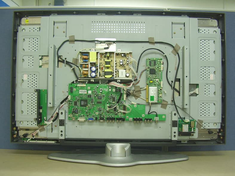
Internal Photos
CERTiTEK Standards Laboratory Co., Ltd. 386-1, Ho-Dong, Yongin-City, Kyungki-Do, Korea 449-100 Tel: +82-31-339-9970 Fax: +82-31-339-9855 http://www.certitek.com/ Test Report No.: 2005050023 Date: May 24, 2005 Page 23 of 34 This Report shall not be reproduced except in full without the written approval of CERTiTEK Form No.: CTK-FF2.0 CERTiTE K EUT Internal Photographs CERTiTEK Standards Laboratory Co., Ltd. 386-1, Ho-Dong, Yongin-City, Kyungki-Do, Korea 449-100 Tel: +82-31-339-9970 Fax: +82-31-339-9855 http://www.certitek.com/ Test Report No.: 2005050023 Date: May 24, 2005 Page 24 of 34 This Report shall not be reproduced except in full without the written approval of CERTiTEK Form No.: CTK-FF2.0 CERTiTE K PCB CERTiTEK Standards Laboratory Co., Ltd. 386-1, Ho-Dong, Yongin-City, Kyungki-Do, Korea 449-100 Tel: +82-31-339-9970 Fax: +82-31-339-9855 http://www.certitek.com/ Test Report No.: 2005050023 Date: May 24, 2005 Page 25 of 34 This Report shall not be reproduced except in full without the written approval of CERTiTEK Form No.: CTK-FF2.0 CERTiTE K CERTiTEK Standards Laboratory Co., Ltd. 386-1, Ho-Dong, Yongin-City, Kyungki-Do, Korea 449-100 Tel: +82-31-339-9970 Fax: +82-31-339-9855 http://www.certitek.com/ Test Report No.: 2005050023 Date: May 24, 2005 Page 26 of 34 This Report shall not be reproduced except in full without the written approval of CERTiTEK Form No.: CTK-FF2.0 CERTiTE K CERTiTEK Standards Laboratory Co., Ltd. 386-1, Ho-Dong, Yongin-City, Kyungki-Do, Korea 449-100 Tel: +82-31-339-9970 Fax: +82-31-339-9855 http://www.certitek.com/ Test Report No.: 2005050023 Date: May 24, 2005 Page 27 of 34 This Report shall not be reproduced except in full without the written approval of CERTiTEK Form No.: CTK-FF2.0 CERTiTE K CERTiTEK Standards Laboratory Co., Ltd. 386-1, Ho-Dong, Yongin-City, Kyungki-Do, Korea 449-100 Tel: +82-31-339-9970 Fax: +82-31-339-9855 http://www.certitek.com/ Test Report No.: 2005050023 Date: May 24, 2005 Page 28 of 34 This Report shall not be reproduced except in full without the written approval of CERTiTEK Form No.: CTK-FF2.0 CERTiTE K CERTiTEK Standards Laboratory Co., Ltd. 386-1, Ho-Dong, Yongin-City, Kyungki-Do, Korea 449-100 Tel: +82-31-339-9970 Fax: +82-31-339-9855 http://www.certitek.com/ Test Report No.: 2005050023 Date: May 24, 2005 Page 29 of 34 This Report shall not be reproduced except in full without the written approval of CERTiTEK Form No.: CTK-FF2.0 CERTiTE K CERTiTEK Standards Laboratory Co., Ltd. 386-1, Ho-Dong, Yongin-City, Kyungki-Do, Korea 449-100 Tel: +82-31-339-9970 Fax: +82-31-339-9855 http://www.certitek.com/ Test Report No.: 2005050023 Date: May 24, 2005 Page 30 of 34 This Report shall not be reproduced except in full without the written approval of CERTiTEK Form No.: CTK-FF2.0 CERTiTE K CERTiTEK Standards Laboratory Co., Ltd. 386-1, Ho-Dong, Yongin-City, Kyungki-Do, Korea 449-100 Tel: +82-31-339-9970 Fax: +82-31-339-9855 http://www.certitek.com/ Test Report No.: 2005050023 Date: May 24, 2005 Page 31 of 34 This Report shall not be reproduced except in full without the written approval of CERTiTEK Form No.: CTK-FF2.0 CERTiTE K CERTiTEK Standards Laboratory Co., Ltd. 386-1, Ho-Dong, Yongin-City, Kyungki-Do, Korea 449-100 Tel: +82-31-339-9970 Fax: +82-31-339-9855 http://www.certitek.com/ Test Report No.: 2005050023 Date: May 24, 2005 Page 32 of 34 This Report shall not be reproduced except in full without the written approval of CERTiTEK Form No.: CTK-FF2.0 CERTiTE K
Test Setup Photos
CERTiTEK Standards Laboratory Co., Ltd. 386-1, Ho-Dong, Yongin-City, Kyungki-Do, Korea 449-100 Tel: +82-31-339-9970 Fax: +82-31-339-9855 http://www.certitek.com/ Test Report No.: 2005050023 Date: May 24, 2005 Page 19 of 34 This Report shall not be reproduced except in full without the written approval of CERTiTEK Form No.: CTK-FF2.0 CERTiTE K APPENDIX B - Test Setup Photos and Configuration Conducted Voltage Emissions CERTiTEK Standards Laboratory Co., Ltd. 386-1, Ho-Dong, Yongin-City, Kyungki-Do, Korea 449-100 Tel: +82-31-339-9970 Fax: +82-31-339-9855 http://www.certitek.com/ Test Report No.: 2005050023 Date: May 24, 2005 Page 20 of 34 This Report shall not be reproduced except in full without the written approval of CERTiTEK Form No.: CTK-FF2.0 CERTiTE K Radiated Electric Field Emissions
Contact Information
Applicant
Mr. Dong-Suk Cha(Research Engineer)
Test Firm
CTK Co., Ltd.Jang-Hee Hong
Technical Specifications
| # | Rule Parts | Frequency Range | Power Output |
|---|---|---|---|
| 1 | 15B | - | - |
Other Applications from ATEC Co., Ltd.
PDLAV420A
Jan 29, 200642 Inches TFT LCD TV
Equipment Class
JBP - Part 15 Class B Computing Device Peripheral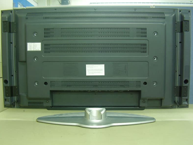
PDLAV370A
Jan 29, 200637 Inches TFT LCD TV
Equipment Class
JBP - Part 15 Class B Computing Device Peripheral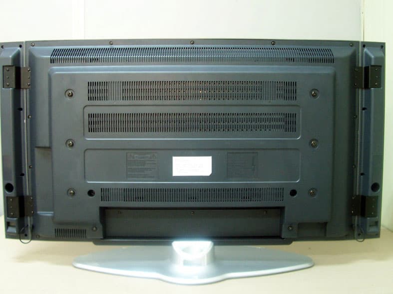
PDLAV370W
May 24, 200537" TFT LCD TV
Equipment Class
JBP - Part 15 Class B Computing Device Peripheral
PDLAV201
Mar 06, 200520.1" LCD TV
Equipment Class
JBP - Part 15 Class B Computing Device Peripheral
PDLAL150N
Dec 14, 200315" LCD Monitor
Equipment Class
JBP - Part 15 Class B Computing Device Peripheral