PDVCONRAVCONDOR/RAVEN METERS
Metering Technology Corporation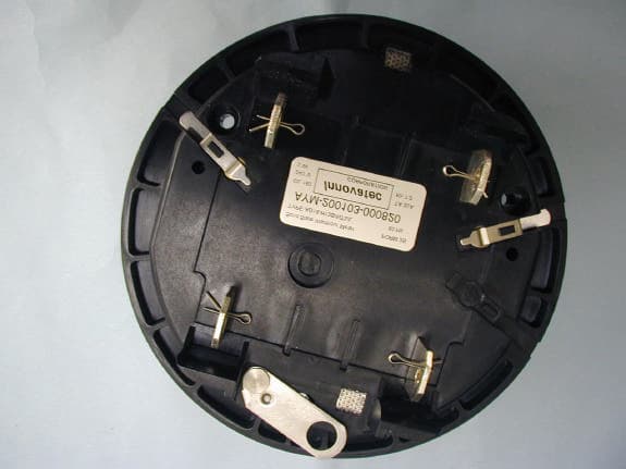
Click to zoom
Application Details
- Equipment Class
- DXT - Part 15 Low Power Transceiver, Rx Verified
- Date of Grant
- Aug 30, 2001
- Application Purpose
- Original Equipment
- Date of Application
- Apr 17, 2001
- Equipment Note
- CONDOR/RAVEN METERS
- Frequency Range
- 792.30000000 - 792.30000000
- Country
- United States
Documents & Files
Document Text
Text extracted from the exhibit documents filed with the FCC. Open a document above to read the original.
Users Manual
Residential Electric Meter Residential ANSI Meter with Remote Disconnect and Wireless Modem Models AD20-H13S/NT2/L AD20-H13S/NT2 Installation and User’s Guide Document Version 1.03, January 2001 Firmware Version 1.00 © 2001 Metering Technology Corporation. All Rights Reserved. This manual, as well as the hardware and software described in it, is furnished under license and may only be used or copied in accordance with the terms of such license. The information in this manual is furnished for informational use only, is subject to change without notice, and should not be construed as a commitment by Metering Technology Corporation. Metering Technology Corporation assumes no responsibility or liability for any errors or inaccuracies that may appear in this book. This manual may not, in whole or in part, be copied, photocopied, reproduced, translated, or converted to any electronic or machine-readable form without prior written consent of Metering Technology Corporation. Trademark Information The Metering Technology Corporation logo and “Global Energy Intelligence” are trademarks of Metering Technology Corporation. Microsoft, Windows, and Windows 95 are registered trademarks of Microsoft Corporation. All other products or name brands are trademarks of their respective holders. Credits Publications team Writer: Sage Knowles Contacting MTC For technical questions or if you’d like more information about Metering Technology Corporation (MTC) and our products, contact us via: Mail360 El Pueblo Drive, Scotts Valley, California, 95066-4212 Phone (831) 438-9999 Fax (831) 440-9988 We b www.metertech.com Installation and User’s Guide iii Contents Installation ...............................................................................................................................................................5 Safety Warnings ............................................................................................................................................... 5 Precautions .................................................................................................................................................. 5 Installing the Meter ......................................................................................................................................... 6 Preparing the Meters for Installation ...................................................................................................... 6 Installing the Meter .................................................................................................................................... 6 LCD Display .............................................................................................................................................................7 Using the Liquid Crystal Display (LCD) ...................................................................................................... 7 Operation Notes .....................................................................................................................................................9 Registered Quantities ...................................................................................................................................... 9 Load Profile ...................................................................................................................................................... 9 Payment Meter Mode .................................................................................................................................... 10 Non-Volatile Memory ................................................................................................................................... 10 Alarm Messages ............................................................................................................................................. 11 iv Residential ANSI Meter with Remote Disconnect and Wireless Modem Installation and User’s Guide 5 CHAPTER 1 I NSTALLATION This chapter provides installation requirements and instructions. It also describes the safety warnings and precautions to use when installing or servicing the Residential Electric ANSI Meters. Warning: Make sure you read the following safety warnings and precautions before you proceed with configuring, installing, and operating the meters. Safety Warnings Before you install and operate your meters, it is important to be familiar with all the safety precautions. Observe these precautions during all phases of operation, service, and repair. Failure to comply with these precautions or with specific warnings elsewhere in this guide violates safety standards of design manufacture and the intended use of the meter. Metering Technology Corporation (MTC) assumes no liability for your failure to comply with these requirements. The information presented in this guide is intended to be an aid to qualified metering personnel. It does not replace the extensive training necessary to handle metering equipment in a safe manner. Warning: Any work on or near energized meters or other metering equipment presents the danger of electrical shock. Only qualified electricians and metering specialists are authorized to work on the meters in accordance with local utility safety practices, utility requirements, and other safety precautions as dictated by local code, regulations, or statutes. Precautions The meter is connected directly to line voltage. Observe all safety warnings as indicated on the meter. Be sure to follow these precautions: • Never service the meter alone. • Be extremely cautious when working around exposed meter socket terminals. Chapter 1 Installation 6 Residential ANSI Meter with Remote Disconnect and Wireless Modem Installing the Meter This section describes the installation requirements and procedure to install the meter. Before you proceed with the installation, make sure you have read the safety warnings and precautions on page 5. Preparing the Met…
Text truncated - open the document above for the full version.
Block Diagram
FREQUENCY SYNTHESIZER DRIVER AMP. 800 MMHz VCO120MHz VCO MICRO- CONTROLLER COMMUNICATION PROCESSOR ASIC DEMODULATOR POWER AMP. LNA T/R SWITCH EEPROM 110 MHz IF FILTER ANTENN A DOWN- CONVERTER UP- CONVERTER DIELECTRIC FILTER 12MHz 32.7KHz NCI BLOCK DIAGRAM SAW FILTER
Cover Letter(s)
360 El Pueblo Drive Scotts Valley, CA 95066 Phone: 831-438-9999 Fax: 831-440-9988 April 11, 2001 Federal Communications Commission Authorization and Evaluation Division 7435 Oakland Mills Road Columbia, MD 21046 Subject: Subject: Letter of Authorization To File ApplicationLetter of Authorization To File Application To whom it may concern: We, the undersigned hereby authorize International Technology Company (ITC), to act on our behalf in all matters relating to applications for equipment authorization, including the signing of all documents relating to these matters. Any and all acts carried out by International Technology Company (ITC) on our behalf shall have the same effect as our own. This authorization expires on April 30, 2002; unless renewed. We the applicant, certify that, in the case of individual applicant, he or she is not subject to a denial of federal benefits pursuant to section 5301 of the Anti-Drug Abuse Act of 1988, 21 USC 853a or in the case of a non-individual application (e.g. corporation, partnership or other unincorporated association), no party to the applicant is subject to a denial of federal benefit pursuant to that section. Thank you. Sincerely yours, Vijay Dhingra VP of Operations Metering Technology Corporation
Cover Letter(s)
USA Facility Europe Facility 9959 Calaveras Road, PO Box 543 Robert-Bosch-Straße 2-4 Sunol, CA 94586-0543 61184 Karben, Germany Tel: (925) 862-2944 Tel: (011) 49-6039-9182-0 Fax: (925) 862-9013 Fax: (011) 49-6039-9182-29 E-mail: [email protected] E-mail: [email protected] International Technology Company (ITC) over 20 years experience in compliance testing and engineering consulting services 9959 Calaveras Road Box 543, Sunol, CA 94586-0543 phone: (925) 862-2944 • fax: (925) 862-9013 • internet: www.itcemc.com ————————EN 45001, NVLAP and VCCI Accredited Laboratory———————————— Date: Tuesday April 17, 2001 Attn.: Authorization and Standards Division Federal Communications Commission Authorization and Evaluation Division 7435 Oakland Mills Road Columbia, MD 21046 File Number: FCC ID: PDVCONRAV Confirmation No.EA100687 Subject: Application for Grant of Equipment Authorization To Whom It May Concern, The enclosed documents constitute a formal submittal and application for a Grant of Equipment Authorization pursuant to Part 15, SubPart C, of the Rules and Regulations of the FCC, regarding Intentional Radiators, as the technical guide. The data in this report demonstrates that the equipment tested complies with the FCC Part 15, SubPart B & C, Open Field Radiated Emissions, Occupied Bandwidth, Harmonics and Spurious Emissions, Maximum Peak Output Power Test limits for Class B & C devices. International Technology Company (ITC) prepared the application on behalf of Metering Technology Corporation. If there are any questions or if further information is needed, please call us at (925) 862- 2944 or fax (925) 862-9013. Thank you. Yours sincerely, ITC USA Facility Europe Facility 9959 Calaveras Road, PO Box 543 Robert-Bosch-Straße 2-4 Sunol, CA 94586-0543 61184 Karben, Germany Tel: (925) 862-2944 Tel: (011) 49-6039-9182-0 Fax: (925) 862-9013 Fax: (011) 49-6039-9182-29 E-mail: [email protected] E-mail: [email protected] Miss Olufunke Aderibigbe Documentation/Publication Manager International Technology Company (ITC). [Sunol-CA]
External Photos
External PhotosExternal Photos Top View of Meter Bottom View of Meter
Internal Photos
Internal PhotosInternal Photos Internal View of Meter Internal Layout of Meter Internal Layout of Meter
Operational Description
360 El Pueblo Drive Scotts Valley, CA 95066 Phone: 831-438-9999 Fax: 831-440-9988 HW Functional Specification of Condor/Raven Meters CONFIDENTIAL & PROPRIETARY By accepting this document, each recipient agrees never to distribute this to others - in whole or in part – without the prior written consent of Metering Technology Corp. Unauthorized copies are prohibited by law. Copyright 1999. Document Revisions Revision Date Author Description 01 12/18/00 VK Original Document 0.0 Related Documents Document Author File Name 1 Residential Energy Meter Requirements Rev 3.00 Fred Schleifer Spec300.pdf 2 Network Communications Firmware Specification Ver. 0.97 Innovatec Corp. 3 Power Supply Specification PS_Specs.pdf 1.0 Introduction This specification describes the architecture and basic functional operation of Condor/Raven Meter (Meter from here on) – the device for measurement of electrical power (energy) supplied to the consumer and for communication with the nearby Gateway Node. 2.0 Hardware Specification The following diagram illustrates the architecture of the Meter. Fig 1. Meter Block Diagram Innovatech Transceiver Power Supply Level Translator Epson EOC88317- F04 uController LCD Two CTs Metering Chip EEPROM 24LC16B Optical Com Port D/A Bus S P I B u s Optical Pulse Output Pulse Stretcher Real Time Clock PROM 27C010 RAM 62C256 FLASH 29F010 2.1 Liquid Crystal Display Radio Meter has an LCD with 7 digits and 7 decimal points. The LCD is configured as 8x9 matrix with the following pinout: P# 1 2 3 4 5 6 7 8 9 10 11 12 13 14 15 16 17 18 Name R0 R1 R2 R3 C0 C1 C2 C3 C4 C5 C6 C7 C8 C9 R4 R5 R6 R7 2.2 Epson EOC88317 MicroController The MicroController used in the Meter is EOC88317-F04. The main functions of the MicroController are: Driving the LCD, Receiving data from the Metering Chip, Storing calibration and configuration parameters in the EEPROM, Communicating with Innovatec Transceiver, Communicating with external optical devices. 2.3 Current transformers Meter has to be able to work with split phase power lines and therefore to measure current in both power lines. The Meter has two Current Transformers and the circuitry for summation of two signals. Current transformers’ ratio is 1000 : 1 and maximum measurable current is 200A. 2.4 Metering Chip The CS5460 is a highly integrated Delta-Sigma Analog-to-Digital Converter (ADC), which combines two Delta-Sigma ADCs, high-speed power calculation functions, and a serial interface on a single chip. It is designed to accurately measure and calculate: Energy, Instantaneous Power, I RMS , and V RMS for single phase 2 or 3-wire power meter applications. The CS5460 interfaces to a CT to measure current, and resistive divider to measure voltage. The CS5460 features an SPI interface for communication with a MicroController and a fixed-width programmable frequency output that is proportional to power. The chip is initialized and fully functional upon power-up, and includes facilities for system-level calibration under control of the user program. The chip has the following technical characteristics: • Energy Data Accuracy: 0.1% of Reading in 1 Second over 300:1 Dynamic Range • On-Chip Functions: Energy, I *V, I RMS and V RMS , Energy to Pulse-Rate Conversion • Complies with IEC 687/1036, JIS • Power Consumption <12 mW • Interface Optimized for Shunt Sensor • Phase Compensation • Ground-Referenced Signals with Single Supply • System Calibration • On-chip 2.5 V Reference (60 ppm/°C drift) • Simple Three-wire Serial Interface • Watch Dog Timer • Power Supply Monitor • Power Supply Configurations • VA+ = +5 V; VA- = 0V; VD+ = +3 V to +5 V • VA+ = +2.5 V; VA- = -2.5 V; VD+ = +3 V 2.5 Real Time Clock The Real Time clock is based on Dallas DS1306 chip and 32.768kHz crystal and provides accuracy of 20ppm. The chip communicates with the MicroController via SPI interface. 2.6 Level Translator The Level translator is needed to communicate with Innovatec transceiver. It is implemented on TC74AC244 chip. 2.7 EEPROM The EEPROM is 24LC16B and works down to 2.5V. 2.8 Optical Communication Port Optical Communication Port uses 38kHz carrier frequency. 2.9 Power Supply The Power Supply is a Printed Circuit Board Assembly from Artesyn. See PS_Specs.pdf. 2.10 Pulse Stretcher The Pulse Stretcher is needed to expand the pulses from Metering chip to ~60ms.
Operational Description
January 21, 2000Residential Energy Meter Requirements Rev 1.00Proprietary InformationPage 1 of 27 Residential Energy Meter Requirements Rev 1.00 Author: Fred Schleifer The Electron Mill, Inc. January 21, 2000Residential Energy Meter Requirements Rev 1.00Proprietary InformationPage 2 of 27 Table of Contents 1INTRODUCTION .....................................................................................................................................................5 1.1 R EFERENCE DOCUMENTS.........................................................................................................................................5 1.2 D EFINITIONS............................................................................................................................................................5 1.3 B ACKGROUND..........................................................................................................................................................5 2SYSTEM REQUIREMENTS ...................................................................................................................................6 2.1 R EFERENCE CONDITIONS.........................................................................................................................................6 2.2 I NPUT REQUIREMENTS.............................................................................................................................................6 2.2.1Operating Voltage Range .............................................................................................................................6 2.2.2Operating Frequency Range.........................................................................................................................7 2.2.3Operating Current Range .............................................................................................................................7 2.2.4Demand-Reset Button ...................................................................................................................................7 2.2.5Display-Mode Button....................................................................................................................................7 2.3 O PTIONAL INPUT REQUIREMENTS............................................................................................................................7 2.3.1Activation Button ..........................................................................................................................................7 2.4 O UTPUT REQUIREMENTS..........................................................................................................................................7 2.4.1IR Calibration LED (Test Output) ................................................................................................................7 2.4.2Display..........................................................................................................................................................7 2.4.3Relay (Actuator) Outputs ..............................................................................................................................8 2.5 O PTIONAL OUTPUTS.................................................................................................................................................9 2.5.1Disconnect Relay ..........................................................................................................................................9 2.6 C ONNECTOR AND INTERFACING REQUIREMENTS.....................................................................................................9 2.6.1Meter Base....................................................................................................................................................9 2.7 S YSTEM ACCURACY REQUIREMENTS.......................................................................................................................9 2.7.1No Load ........................................................................................................................................................9 2.7.2Starting Load ................................................................................................................................................9 2.7.3Load Variation............................................................................................................................................10 2.7.4Power-Factor Variation .............................................................................................................................10 2.7.5Voltage Variation .......................................................................................................................................11 2.7.6Frequency Variation...................................................................................................................................11 2.7.7Load-Current Imbalances...........................................................................................................................12 2.7.8Internal Heating .........................................................................................................................................12 2.7.9Stability over Time......................................................................................................................................13 2.7.10Voltage Interruption ...................................................................................................................................13 2.7.11External Magnetic Field .............................................................................................................................13 2.7.12Temperature Coefficient .............................................................................................................................14 2.7.13Harmonic Power.....................................................…
Text truncated - open the document above for the full version.
Schematics
5 5 4 4 3 3 2 2 1 1 DD CC BB AA DO NOT STUFF UNUSED GATES COM RELAY OPEN OPTIONAL LINE FILTER 4 LAYER BOARD CT2- A CT2- B N/A 2 OPTIONAL LINE_2 First cut ON/OFF RELAY CONTROL Values of shunt resistors R8, R15 calculated for 200A, 1000:1 CTs RELAY CLOSE 13/24/00 POWER FAIL DETECTION Eliminated U2,U8,U4; changed power supply and power fail circuit; added U14, Flash Memory; added frequency measurement circuit. 6/13/00 ADDED R59,R60,NR1(SIDACTOR). DELETED C47,R17,NR1(VARISTOR) CT1- B 30ms min time to switch BYPASS CAP FOR U3 8/8/00 CT1- A This schematic is the property of Metering Technology Corporation, and is confidential and not to be duplicated in any manner without the express written permission of Metering Technology Corporation. Copyright 1999, 2000. Metering Technology Corporation 3 LINE_1 CONNECT D5-3 TO -10V. NO CONNECT TO C44,AND C45. GND-SIGNAL CHANGED TO GND-DIGITAL. CHANGED C12 TO TANT-C 4ADDED REAL-TIME CLOCK WITH BATTERY BACK-UP: ADDED B1,Y5, AND U15. CHANGED TEST POINT DESIGNATIONS. 9/5/00 CHANGED RELAY DRIVER CIRCUIT. ADDED IRDA. REAL-TIME CLOCK (RTC) RTC BATTERY 38 KHz OSCILLATOR OPTIONAL IRDA INTERFACE OPTIONAL TXCO FOR HIGH ACCURACY BYPASS CAP FOR U18 BYPASS CAP FOR U17 BYPASS CAP FOR U15 5DELETED D4; ADDED R69 TO FIX +13V POWER SUPPLY. ADDED C57 BYPASS CAP FOR U15; ADDED R70 TO LIMIT BATTERY I. 10/24/00 6Layout change only. VIN- FROM R12 PAD IIN- FROM R15 PAD 11/14/00 9Layout change only.11/21/00 C58 ADD BY REWORK C59 ADD BY REWORK STUFF FOR CONDOR ONLY STUFF FOR CONDOR ONLY POWER FOR ON/OFF RELAY DRAWNMFG MATL MKTG ENGR ENGR DATEDATE APPROVALSAPPROVALS REVCHANGES / ECO #APPVDDATE SCH0057 9A CONDOR 2 METERING TECHNOLOGY 380 El Pueblo Rd Scotts Valley, CA 95066 12Monday, April 09, 2001 PH: (831) 438-9999 FX: (831) 440-9988 E-Mail: [email protected] Title SizeDocument NumberRev Date:Sheet of 4MHZ C/CS PF2 CSCLK PFMON 110V C/INT VA+ XOUT PO6 XIN PF1 BYPASS PO5 VREF CT2+ PULSE_OUT VD+ CT1+ L1_FILTER R_CLOSE PO3 PO2PO4 C/RST IIN+ PO1 DIR SEC1 L2_FILTER 32KHZ_X1 32KHZ_X2 32KHZ_TEST SEC2SEC3 RO1 RC1 RO2 RC2 R_OPEN CSDI CSDO VIN+ 76KHZ_1 38KHZ_MOD1 76KHZ_2 38KHZ_2 +5V_RX 38KHZ_MOD2 38KHZ_MOD3 IR_TX1 IR_TX3 38KHZ_1 76KHZ_OUT 76KHZ_CLK IR_TX2 76KHZ_IN SEC1A 3V_BAT+ MISO SCL MOSI LINE_2 LINE_2 /MC_INT /MC_CS LINE_2 RELAY_OPEN LINE_2 RES_ RELAY_CLOSE MISO MOSI SCL RTC_CE IR_RX UART_RES/IR_TX +5V +5V +5V +5V +5V +5V +3.6V +3V +5V+3V +5V +13VDC +13VDC +5V +5V +5V +5V +3V +5V +5V +5V +5V +5V U18A 74HC04 12 C52 47 pF TP21 1 + C44 22uF 20%, 400V U17B 74HC73 7 5 10 9 8 6 2J 2CLK 2K 2Q 2Q 2CLR C53 47 pF R63 1K 5% 1/10W D6 13V, 350 mW BZX84-C13 U1 CS5460 1 2 3 4 5 6 7 8 9 10 11 12 13 14 15 16 17 18 19 20 21 22 23 24 XOUT CPUCLK VD+ DGnd SCLK SDO /CS NC Vin+ Vin- Vrefout Vrefin VA- VA+ Iin- Iin+ PFMON NC /RST /INT OUT DIR SDI XIN H6 D080 TP4 1 OPT1 OED-EL-8L TP14 1 U18E 74HC04 1110 R10 NS 1/10W U18D 74HC04 98 R48 51 1/10W 5% C57 0.1uF R70 ZERO 5% 1/10W Y6 32.768KHz D4 C4 D5 D2 C2 C3 D3 A4 A5 A1 B4 B5 A6 A2 A3 C5 C7 C8 C9 D1 B8 B9 C1 C6 A7 A8 A9 B1 B2 B3 B6 B7 D6 D7 D8 D9 OUT OUT OUT VCC VCC VCC VCC VBAT VBAT GND VBAT VBAT GND GND GND OUT GND GND GND GND GND GND GND GND GND GND GND GND GND GND GND GND GND GND GND GND TP22 1 R69 220 1/8W, 5% OPT3 SFH5110 IR RECEIVER 1 2 3 C6 NS R16470 5%1/16W TP20 1 C7 0.1uF R8 0.05, 1% D12 BAS16 R31 33K, 5% 1/10W Q1 MMBT3906 1 2 3 U5 ARTESYN 708435-002-KIT 3 4 1 2 5 +5V RTN LINE 2 LINE 1 SEC R61 10M R62 10k D15 MUR120 200V 1A 2 1 Q7 MMBT3906 1 2 3 TP10 1 Q8 MMBT3904 1 2 3 TP48 1 L210 uH Q6 FDS6930A 4 5 3 6 21 7 8 H5 D080 U3B 74HC14 34 H7 R24 180 1/8W 5% R27 3.3K, 5% 1/8W R9470 5%1/16W Q9 MMBT3904 1 2 3 Y5 32.768KHZ H3 D080 C56 0.1uF C58 180pF H9 + C15 10.0uF, 10%, 16V TANTALUM R65 47 C54 1uF TP6 1 R57 200K 1% 1/10W C59 180pF TP11 1 U17A 74HC73 14 1 3 12 13 2 2J 2CLK 2K 2Q 2Q 2CLR NR1 PP3500SC 500A H4 D080 H1 D080 L1 10mH 0.45A 250V 1 4 2 3 U18C 74HC04 56 C9 0.039uFC42 0.1uF TP15 1 C48 0.1uF 10% 250VAC R50 10K 5% 1/10W TP13 1 R49 220K 1/2W5% U18F 74HC04 1312 R15 0.05, 1% TP25 1 D14 MUR120 200V 1A 21 R11470 5%1/16W Y7 76.79 kHz R14470 5%1/16W TP24 1 TP50 1 TP8 1 TP26 1 U18B 74HC04 34 + C17 22.0uF TANT-C 20%, 16V R54 NS D1 SCHOTTKY BAT54 TP17 1 R61K 5%1/10W R53 NS C55 0.1uF H8 OPT2 LED_IR R2 68 1/10W 5% R12 121 1/8W 1% C50 LAB-SET +C20 10,000uF 20%, 16V + C16 22.0uF TANT-C 20%, 16V R4 169K 1/4W1% R33 220 1/8W, 5% R201K 5%1/10W C4 0.1uF U6 TC1185-3.6VCT 3 1 2 4 5 /SHDN VIN GND BYPASS VOUT B1 LITHIUM 3VDC P N TP1 1 C19 1uF TP53 1 U15 DS1306 20 10 1 2 5 8 9 3 18 17 16 15 14 11 7 12 VCC1 GND VCC2 VBAT X2 INT1 1Hz X1 32KHz VCCIF SDO SDI SCLK SERMODE INT0 CE C51 LAB-SET R26 3.3K, 5% 1/8W R32 33K, 5% 1/10W R5 169K 1/4W1% TP9 1 TP12 1 TP49 1 C3 0.1uF H11 D080 TP19 1 C5 NS C49 0.1uF + C12 10.0uF, 10%, 16V TANTALUM R18470 5%1/16W R7470 5%1/16W R67 1K R19 1.6M 1/16W 5% TP5 1 C43 470pF R64 33 5% 1/10W H10 D080 U3D 74HC14 98 U3A 74HC14 12 D3 BAW56 R68 1K Y2 4.096MHz TP18 1 H2 D080 R66 33K TP7 1 U3F 74HC14 1312 5 5 4 4 3 3 2 2 1 1 DD CC BB AA METERING TECHNOLOGY OPTIONAL: STUFF R58 INSTEAD OF D7,C33,AND R45, IF TILT SWITCH IS USED. OPTIONAL FOR POWER FAIL DATA RAM 32K PROGRAM PROM 128K TAMPER DETECTION LCD DISPLAY CALIBRATION CONNECTOR NCI (RADIO I/F) NCI SYNC operation. TILT SWITCH OR WEIGHTED REED SWITCH FLASH 128K FREQUENCY MEASUREMENT This schematic is the property of Metering Technology Corporation, and is confidential and not to be duplicated in any manner without the express written permission of Metering Technology Corporation. Copyright 1999, 2000. Metering Technology Corporation FOUT BUSY FOUT (MODEM) BUSY (MODEM) (MODEM CONNECTOR) FOR MODEM, ADD 2 JUMPER WIRES SCH0057 9A CONDOR 2 22Monday, April 09, 2001 Title SizeDocument NumberRev Date:Sheetof C08 PU3 FREQUENCY CD E_A11 E_A16 VC5 C01 E_D4 CE ROW0 E_A1 C00 E_A14 E_A14 CA C05 E_A8 E3 E_A12 ROW7 E_A10 VC3 E_A9 C09 SPIIN VC2 SPICLK ROW5 C03 E_A12 ROW2 E_A13 E_A2 E1 E5 E_A0 C01 C08 C00 E_A0 SPIO E_A7 VC1 E_A0 E23 E_A12 EE_DATA E_A3 E_A5E_A5 C04 ROW0 E_A2 E_A14 TAMP2 E_A16 E_A2 C06 E_A8 E_A2 E_A11 E_A5 FREQ1 E_D[0..7…
Text truncated - open the document above for the full version.
Schematics
5 5 4 4 3 3 2 2 1 1 DD CC BB AA RF SHIELD AT GROUND POTENTIAL 50 OHM MICROTRIP LINE (30x140) PIN DIODE 50 OHM MICROTRIP LINE (30xL) 1/4 WAVELENGTH STUB, 30x1735 50 OHM MICROTRIP LINE (30xL) 50 OHM MICROTRIP LINE (30xL) 50 OHM MICROTRIP LINE (30xL) 04/19/00 03/30/00 03/09/00 1204REPLACE Q9, R70,R84. NEW TRACE WIDTH = PCB = 24mils 5.3 5.2 P.F. P.F. 1200 NEW U14,R18,R22,R99, SHEILDS,PCB REV. 5.2 1213 P.F. 5.505/10/001218V.P.C43, C44 VALUE CHANGE FROM 8.2pF TO 10pF 06/22/001231V.P.5.6C43, C44 VALUE CHANGE FROM 10pF TO 9.1pF 5.4 1239C92, C94 VALUE CHANGE FROM 10pF TO 12pF V.P.07/27/005.7 R28, R29 CHANGE FROM 2.0KTO 2.2K RES. V.P.12545.810/19/00 Add Innovatec Part numbering5.9125711/17/00P.F. 12685.10Change L7 to 0805CS-080XJBC.P.F.01/04/01 971-00003 5.10 SCH: NCI INNOVATEC B 14Monday, January 08, 2001 Title SizeDocument NumberRev Date:Sheet of 5.102/01/00INITIAL RELEASE ZONEREVDATEECO NO.APPROVED REVISIONS DESCRIPTION TXEN TXEN TXOUT /RXEN RXEN TXEN /TXEN RXIN +3.6V +5.0V +3.6V 20 dB U8 UPC2771TB 4 6 2 1 35 C136 NP C132 39PF C88 3.3PF R71 100 D1 NP C111 39PF Q9 BDP31 2,4 1 3 C110 100PF AT112 C116 100PF C123 8.2 PF C140 3.3PF BPF DF1 TDFM2A-915E-10 1 2 3 4 L29 68NH J6 RF CONNECTOR 1 2 C86 100PF SAW SF2 SAFC915MA70N 134 5 6 2 R56 4.7K L26 39NH R70 1.2K C138 22PF C134 0.01UF AT115 R80 10K C135 22 PF 20 dB U4 UPC2748TB 4 6 2 1 35 C104 39PF R76 51 Q6 MMBT3904LT1 3 1 2 AT117 AT114 R84 22K C28 100PFR77 51 L27 NP U9 ITT2104AF 1 3,4,6,7,10 5 2,8,9 12 16 11,13,14,15 VDD1 GND RF in N/C RF out/Vdd3 VDD2 GND C125 4700PF Q8 MMBT3906LT1 3 1 2 R78 NP C142 39PF C127 0.1UF Q3 MMBT3906LT1 3 1 2 C93 39PF C87 6800PF Q5 MMBT3906LT1 3 1 2 C129 NP C122 1000PF C121 1000PF R74 10 R55 NP R72 NP L22 8.2NH R73 4.7K AT119 AT116 U11 UPG137GV 1 2 36 7 8 54 VC2 O2 GNDGND O1 VC1 INGND AT118 C103 39PF 5 5 4 4 3 3 2 2 1 1 DD CC BB AA NEW FIRMWARE MANUAL TEST AT21 AT20 OPERATION MODE L L L L H H HH RX CONSTANT TX MOD TX NORMAL RF SHIELD AT GROUND POTENTIAL 971-000035.10 SCH: NCI, CONTROLLER INNOVATEC B 24Monday, January 08, 2001 Title SizeDocument NumberRev Date:Sheet of TXEN_N RXEN_N CS/PULSE DSOUT MODOUT EN /EN RXEN /RXEN TXEN /TXEN LE DATA CLK REFOSC TXGAIN +3.6V +3.6V +3.6V +3.6V +3.6V +3.6V +5.0V +3.6V +3.6V AT85 R89 NP AT63 AT3 AT58 AT24 AT105 AT14 C99 0.01UF AT25 R67 4.7K X2 12.0MHZ U14 MAX809 23 1 RESETVCC GND R91 4.7K R10 0 FB1 BLM31P500S AT10AT11AT12 AT83 U7D 74VHC00 12 13 11 C96 22PF C141 0.01UF AT57 AT17 C112 TBD R90 NP AT2 C94 12PF AT15 U6 24LC01 1 2 3 4 5 6 7 8 A0 A1 A2 VSS SDA SCL WP VCC U7B 74VHC00 4 5 6 R58 2M C114 TBD AT18 AT21 AT8 R644.7K C115 39PF AT56 AT82 AT5 R98 100 AT81 AT86 C92 12PF AT9 R109 100K AT61 Q7 MMBT3904LT1 3 1 2 AT1 R180 J2 11X2 PITCH HEADER 1 3 5 7 9 11 13 15 17 19 21 2 4 6 8 10 12 14 16 18 20 22 1 3 5 7 9 11 13 15 17 19 21 2 4 6 8 10 12 14 16 18 20 22 AT22 R63 100 U5 300-00003 12345678910111213 14 15 16 17 18 19 20 21 22 23 24 25 26 27282930313233343536373839 40 41 42 43 44 45 46 47 48 49 50 51 52 VDDRSTTSTBXFOUTXFOUTXFINXSOUTXSINSCLSDALOCKCLKDATA LE TXEN RXEN MODE CS/PULSE VSS TEST1 TEST0 MODOUT DI RTS/TAMPER RADEN DIREF P2.0/SEG8P2.1/SEG9 P2.2/SEG10P2.3/SEG11P2.4/SEG12P2.5/SEG13P2.6/SEG14P2.7/SEG15 AVSS AVDD P0.0/SEG0P0.1/SEG1P0.2/SEG2 P0.3/SEG3 P0.4/SEG4 P0.5/SEG5 P0.6/SEG6 P0.7/SEG7 P1.0/COM0 P1.1/COM1 P1.2/COM2 P1.3/COM3 SYNC/LBD SPIO/EEPWR SPIIN/ACT2 SPICLK/ACT1 R101 4.7K AT54 R61 2.2K R220 C91 0.01UF AT64 AT16 AT7AT4 R88 NP R59 2M C137 0.01UF C113 39PF AT19 R341.0K AT53 AT84 AT62 R62 2.2K U7A 74VHC00 1 2 3 14 7 AT104 R69 0 AT69 AT55 AT23 AT80 R65 0 R92 1.5K X1 32.768K AT27 R66 4.7K C95 22PF AT20 AT13 AT6 + C90 1.0UF U7C 74VHC00 9 10 8 R75 4.7K FB2 BLM11B471SD 5 5 4 4 3 3 2 2 1 1 DD CC BB AA 50 OHM MICRO STRIP LINE, W=30 RF SHIELD AT GROUND POTENTIAL RF SHIELD AT GROUND POTENTIAL 971-00003 5.10 SCH: NCI SYNTHESIZER MAX 2463 INNOVATEC B 34Monday, January 08, 2001 Title SizeDocument NumberRev Date:Sheet of TXOUT FIN MODOUT TXEN TXEN CPO TXIN EN FI…
Text truncated - open the document above for the full version.
Contact Information
Applicant
Steve Sefick(VP Engineering)
Technical Contact
INTERNATIONAL TECHNOLOGY COMPANYMICHAEL GBADEBO
[email protected]925-862-2944
9959 CALAVERAS ROAD · SUNOL, California · United States
Non-Technical Contact
INTERNATIONAL TECHNOLOGY COMPANYOLUFUNKE ADERIBIGBE
[email protected]925-862-2944
Test Firm
ITC Engineering Services, Inc.Michael Gbadebo
Technical Specifications
| # | Rule Parts | Frequency Range | Power Output |
|---|---|---|---|
| 1 | 15C | 792.3 MHz - 792.3 MHz | - |
Other Applications from Metering Technology Corporation
PDVRFLAN
Dec 11, 2002RFLAN Module
Equipment Class
DSS - Part 15 Spread Spectrum Transmitter