PDVRFLANRFLAN Module
Metering Technology Corporation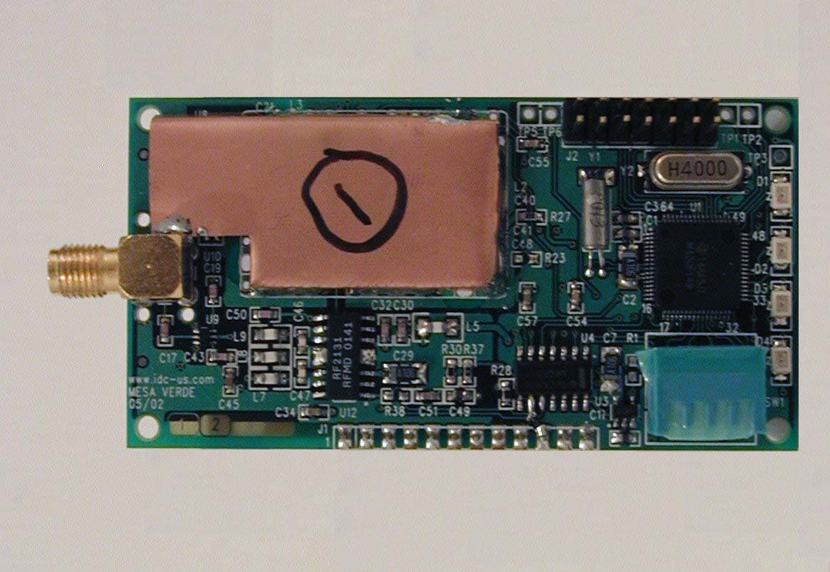
Click to zoom
Application Details
- Equipment Class
- DSS - Part 15 Spread Spectrum Transmitter
- Date of Grant
- Dec 11, 2002
- Application Purpose
- Original Equipment
- Date of Application
- Oct 10, 2002
- Equipment Note
- RFLAN Module
- Frequency Range
- 902.00000000 - 928.00000000
- Country
- United States
Documents & Files
Document Text
Text extracted from the exhibit documents filed with the FCC. Open a document above to read the original.
Users Manual
Tested and Report Prepared By: FCC ID: PDVRFLAN ITC Engineering Services 9959Calaveras Road, Box 543 Sunol, CA 94586-0543 Tel: 925-862-2944 Fax: 925-862-9013 Email: [email protected] Web: www.itcemc.com RF-LAN Module User’s Guide v1.01 September 23, 2002 RF-LAN User’s Guide v1.01 -- Confidential – FCC ID: PDVRFLAN 2002 Metering Technology Corporation. All Rights Reserved Page 2 FCC WARNING STATEMENTS Note: This equipment has been tested and found to comply with the limits for a Class B digital device, pursuant to Part 15 of the FCC. Rules: These limits are designed to provide reasonable protection against harmful interference in a residential/office installation. The equipment generates, uses, and can radiate radio frequency energy, and if not installed and used in accordance with the instructions, may cause harmful interference to radio communications. However, there is no guarantee that interference will not occur in a particular installation. If this equipment does cause harmful interference to radio or television reception, which can be determined by turning the equipment off and on, the user is encouraged to try to correct the interference by one or more of the following measures: • Reorient or relocate the receiving antenna. • Increase the separation between the equipment and receiver. • Connect the equipment into an outlet on a circuit different from that to which the receiver is connected. • Consult the dealer or an experienced Radio/TV technician for help. CAUTION: Changes or modifications not expressly approved by the party responsible for compliance could void the user’s authority to operate the equipment. FCC LABEL STATEMENT This device complies with FCC Rules Part 15. Operation is subject to the following two conditions: (1) This device may not cause harmful interference and (2) This device must accept any interference that maybe received, including interference that may cause undesired operation. INSTRUCTIONS TO THE INSTALLER & USER Minimum Safe Distance: 0.14943 meters (5.9 inches) Antenna Substitution: Do not substitute any antenna for for the one supplied by the manufacturer. You may be exposing person(s) to harmful radiation. Contact supplier or the manufacturer for further instructions. Table of Contents Operational Overview...............................................................................................................................4 Electrical Specifications............................................................................................................................4 Hardware Description...............................................................................................................................5 Software Description.................................................................................................................................6 Commands To RF LAN Card:..............................................................................................................7 Connector Details......................................................................................................................................7 J1 Connector.........................................................................................................................................7 J2 Connector.........................................................................................................................................8 J3 Connector.........................................................................................................................................8 RF-LAN User’s Guide v1.01 -- Confidential – FCC ID: PDVRFLAN 2002 Metering Technology Corporation. All Rights Reserved Page 4 Operational Overview The purpose of the RF-LAN Module is to provide communication over the air to another similar unit or an RF-LAN Hub. The RF-LAN Module can be installed in different types of host electronic measurement, control, and data acquisition equipment, such as electric meters. The following describes the general operation of the RF-LAN Module: • The Module operates in ISM band (902 – 928 MHz) using the Frequency Hopping method. • The Module can be installed in devices that provide a 5VDC power supply. • Communication with the host device is accomplished through a 9600 baud serial interface. • The Module adjusts output RF power according to reception of an acknowledgment signal. • The Module can communicate with a similar Module located in other devices, such as a Gateway, and with low power RF transceivers located nearby inside devices like Water or Gas Meters. Electrical Specifications Operating Voltage: 5VDC +/- 5% Consumed Current : < 1A, peak Effective Radiated Output RF Power with Tuned Antenna: 10, 15, 20, 25, 30 dBm, programmable Frequency Range: 902 – 928 MHz Number of Channels: 50, minimum Data Rate: 1200, 2400, 4800, 9600, programmable Receiver Sensitivity: -105dBm, maximum Adjacent Channel Rejection: 45dBc, min Out of Band Signal Rejection: 60dBc, min Frequency Synthesizer Steps: 500Hz, max RF Input/Output Impedance: 50 Ohm Receiver Saturation: 126 dBuV/m, min RF-LAN User’s Guide v1.01 -- Confidenti al – FCC ID: PDVRFLAN 2002 Metering Technology Corporation. All Rights Reserved Page 5 Hardware Description The main building blocks of the RF-LAN Module are the microcontroller, the RF transceiver, and the 1-Watt RF power amplifier, as shown in the following Figure 1: Block Diagram of RF-LAN Module. MSP430F149 Microcontroller Connector J1 to Meter RF Transceiver CHIPCON CC1000 Tx Path 1W PA T/R Switch Rx Path LNA , SAW FILTER and Glue Logic Line Filter and 3.3V LDO Data Control Using RSSI 3.3V Filter 3.3V Filter ENB RF Tx in Progress RFLAN Reset Status RFLAN Tx Input RFLAN Rx Output RFLAN Reset Input RFLAN Mode Input VCC 5V V C C 3 . 3 V Analog Vcc Digital Vcc VCC 3.3V CC1000 TX-OUT C C 1 0 0 0 - A L E C C 1 0 0 0 - P C L K C C 1 0 0 0 - P D A T A 32 KHz 11.059 MHz Block Diagram Of Mesa Verde Project 4.0 MHz…
Text truncated - open the document above for the full version.
Users Manual
Tested and Report Prepared By: FCC ID PDVRFLAN ITC Engineering Services 9959Calaveras Road, Box 543 Sunol, CA 94586-0543 Tel: 925-862-2944 Fax: 925-862-9013 Email: [email protected] Web: www.itcemc.com RF-LAN Module User’s Guide v1.02 December 3, 2002 RF-LAN User’s Guide v1.02 -- Confidential – FCC ID PDVRFLAN 2002 Metering Technology Corporation. All Rights Reserved Page 2 FCC WARNING STATEMENTS Note: This equipment has been tested and found to comply with the limits for a Class B digital device, pursuant to Part 15 of the FCC. Rules: These limits are designed to provide reasonable protection against harmful interference in a residential/office installation. The equipment generates, uses, and can radiate radio frequency energy, and if not installed and used in accordance with the instructions, may cause harmful interference to radio communications. However, there is no guarantee that interference will not occur in a particular installation. If this equipment does cause harmful interference to radio or television reception, which can be determined by turning the equipment off and on, the user is encouraged to try to correct the interference by one or more of the following measures: • Reorient or relocate the receiving antenna. • Increase the separation between the equipment and receiver. • Connect the equipment into an outlet on a circuit different from that to which the receiver is connected. • Consult the dealer or an experienced Radio/TV technician for help. CAUTION: Changes or modifications not expressly approved by the party responsible for compliance could void the user’s authority to operate the equipment. FCC LABEL STATEMENT This device complies with FCC Rules Part 15. Operation is subject to the following two conditions: (1) This device may not cause harmful interference and (2) This device must accept any interference that maybe received, including interference that may cause undesired operation. INSTRUCTIONS TO THE INSTALLER & USER Minimum Safe Distance: 20 centimeters (7.9 inches) Antenna Substitution: Do not substitute any antenna for the one supplied by the manufacturer. You may be exposing person(s) to harmful radiation. Contact supplier or the manufacturer for further instructions. RF-LAN User’s Guide v1.02 -- Confidential – FCC ID PDVRFLAN Table of Contents Operational Overview...............................................................................................................................4 Electrical Specifications............................................................................................................................4 Hardware Description...............................................................................................................................5 Software Description.................................................................................................................................6 Commands To RF LAN Card:..............................................................................................................7 Connector Details......................................................................................................................................7 J1 Connector.........................................................................................................................................7 J2 Connector.........................................................................................................................................8 J3 Connector.........................................................................................................................................8 RF-LAN User’s Guide v1.02 -- Confidential – FCC ID PDVRFLAN 2002 Metering Technology Corporation. All Rights Reserved Page 4 Operational Overview The purpose of the RF-LAN Module is to provide communication over the air to another similar unit or an RF-LAN Hub. The RF-LAN Module can be installed in different types of host electronic measurement, control, and data acquisition equipment, such as electric meters. The following describes the general operation of the RF-LAN Module: • The Module operates in ISM band (902 – 928 MHz) using the Frequency Hopping method. • The Module can be installed in devices that provide a 5VDC power supply. • Communication with the host device is accomplished through a 9600 baud serial interface. • The Module adjusts output RF power according to reception of an acknowledgment signal. • The Module can communicate with a similar Module located in other devices, such as a Gateway, and with low power RF transceivers located nearby inside devices like Water or Gas Meters. Electrical Specifications Operating Voltage: 5VDC +/- 5% Consumed Current : < 1A, peak Effective Radiated Output RF Power with Tuned Antenna: 10, 15, 20, 25, 30 dBm, programmable Frequency Range: 902 – 928 MHz Number of Channels: 54 Data Rate: 1200, 2400, 4800, 9600, programmable Receiver Sensitivity: -103dBm Adjacent Channel Rejection: 45dBc, min Out of Band Signal Rejection: 60dBc, min Frequency Synthesizer Steps: 500Hz, max RF Input/Output Impedance: 50 Ohm Receiver Saturation: 126 dBuV/m, min RF-LAN User’s Guide v1.02 -- Confidential – FCC ID PDVRFLAN 2002 Metering Technology Corporation. All Rights Reserved Page 5 Hardware Description The main building blocks of the RF-LAN Module are the microcontroller, the RF transceiver, and the 1-Watt RF power amplifier, as shown in the following Figure 1: Block Diagram of RF-LAN Module. MSP430F149 Microcontroller Connector J1 to Meter RF Transceiver CHIPCON CC1000 Tx Path 1W PA T/R Switch Rx Path LNA , SAW FILTER and Glue Logic Line Filter and 3.3V LDO Data Control Using RSSI 3.3V Filter 3.3V Filter ENB RF Tx in Progress RFLAN Reset Status RFLAN Tx Input RFLAN Rx Output RFLAN Reset Input RFLAN Mode Input VCC 5V V C C 3 . 3 V Analog Vcc Digital Vcc VCC 3.3V CC1000 TX-OUT C C 1 0 0 0 - A L E C C 1 0 0 0 - P C L K C C 1 0 0 0 - P D A T A 32 KHz 11.059 MHz Block Diagra…
Text truncated - open the document above for the full version.
Users Manual
Tested and Report Prepared By: FCC ID PDVRFLAN ITC Engineering Services 9959Calaveras Road, Box 543 Sunol, CA 94586-0543 Tel: 925-862-2944 Fax: 925-862-9013 Email: [email protected] Web: www.itcemc.com MTC CONFIDENTIAL INFORMATION PRODUCT: ASSSEMBLY PART NUMBER: REV: Puma ASSEMBLY INSTRUCTION FOR LAN Radio and Meter ASSY# PRD0900 CREATED BY: DATE: Kent Vogel 11/12/02 APPROVED: DATE: METERING TECHNOLOGY Carlos Cuturrufo 02 CORPORATION APPROVED: DATE: Scotts Valley, CA QA: Kent Vogel DATE: 02 DATE: DOCUMENT NUMBER: REVISION: PAGE OF 11/12/02 ASI0021 A 1 2 FORM: xxxxxxxxxxxx Tested and Report Prepared By: FCC ID PDVRFLAN ITC Engineering Services 9959Calaveras Road, Box 543 Sunol, CA 94586-0543 Tel: 925-862-2944 Fax: 925-862-9013 Email: [email protected] Web: www.itcemc.com MTC CONFIDENTIAL INFORMATION PRODUCT: ASSSEMBLY PART NUMBER: REV: Puma DATE: DOCUMENT NUMBER: REVISION: PAGE OF 11/12/02 ASI0021 A 2 2 FORM: xxxxxxxxxxxx DOCUMENT REVISION HISTORY DOC REV REASON FOR CHANGE DESCRIPTION OF CHANGE DATE A Initial Release Release of Instruction 11-12-2002 Procedure: 1. Place the meterboard on the top of the base assembly. Attach the power connector assembly, CT connector assembly, and battery to the meterboard. Snap the meterboard onto the base skirt. 2. Attach the display bracket to the top of the board. Install the flex cable from the LCD to the meterboard, then snap the LCD into the display bracket. 3. Install the LAN radio card to the side of the base skirt using the plastic plunger rivets. 4. Install the LAN antenna board to the display bracket using the pine tree rivets. 5. Connect the flex circuit between the LAN radio and the meterboard. 6. Solder the coax cable between the LAN antenna and the LAN radio. 7. Install the cover seal to the base rib. 8. Place the bezel over the meter base and align the slots so that it snaps into place onto the base skirt. 9. Add label with the following notation: « Contains FCC ID: PDVRFLAN », MTC p/n. XXXXXXXXX to the top surface of the meter bezel 10. Install the cover assembly as the final step to the meter.
Cover Letter(s)
ITC Engineering Services Over 20 years experience in Compliance Testing and Engineering Consulting Services ———————————————————————————————————————————————————————— Date: Friday October 11, 2002 Attn.: Authorization and Standards Division Federal Communications Commission Authorization and Evaluation Division 7435 Oakland Mills Road Columbia, MD 21046 File Number: FCC ID: PDVRFLAN Subject: Application for Grant of Equipment Authorization To Whom It May Concern, The enclosed documents constitute a formal submittal and application for a Grant of Equipment Authorization pursuant to Part 2.938 and 15.201 of the Rules and Regulations of the FCC, regarding Intentional Radiators. The data in this report demonstrates that the equipment tested complies with the FCC Part 15, Subpart B & Subpart C (Open Field Radiated Emissions, Occupied Bandwidth, Maximum Peak Output Power and Transmitted Power Density, Radiated Harmonics and Spurious Emissions) test limits for devices operating under the provisions of this part. This application was prepared by International Technology Company (ITC). If there are any questions or if further information is needed, please call us at (925) 862-2944 or fax (925) 862-9013. Thank you. Yours sincerely, Bandele Adepoju ITC ————————————————EN 45001, NVLAP and VCCI Accredited Laboratory———————————————— 9959 Calaveras Road, Box 543, Sunol, CA 94586-0543 Phone: (925) 862-2944 • (888) 336-7625 • Fax: (925) 862-9013 E-mail: [email protected] • Web: www.itcemc.com
Cover Letter(s)
ITC Engineering Services Over 20 years experience in Compliance Testing and Engineering Consulting Services ———————————————————————————————————————————————————————— 9959 Calaveras Road, Box 543, Sunol, CA 94586-0543 Phone: (925) 862-2944 • (888) 336-7625 • Fax: (925) 862-9013 E-mail: [email protected] • Web: www.itcemc.com Date: December 03, 2002 Attn.: Mr Steve Dayhoff Authorization and Standards Division Federal Communications Commission Authorization and Evaluation Division 7435 Oakland Mills Road Columbia, MD 21046 Re: FCC ID: PDVRFLAN Applicant: Metering Technology Corporation Correspondence Reference Number: 24410 731 Confirmation Number: EA808287 Dear Mr. Dayhoff, With reference to your request, please find the following response 1. The installation instructions has been revised to indicate that at least 20cm (7.9 inches) separation shall be provided between the antennas and the people. A copy of the User Manual is attached. 2 The RFLAN, FCC ID: PDVRFLAN, is a complete transmitter with its own reference oscillator. It is provided with a Chipcon single chip UHF Transceiver, Model CC1000. Please refer to the attached data sheet on the Chipcon transceiver. The Grantee (MTC) will retain control over the final installation of the RF LAN, and full compliance of the end product will always be ensured by the Grantee. The Grantee will be responsible for the compliance of the RFLAN in its final configuration. Please refer to page 2 of the attached Theory of Operations manual. The RFLAN meets all of the requirements for a Part 15 modular transmitter, as required by FCC Public Notice DA 00-1407, as demonstrated by the attached exhibits, including test report. 3. The end product is a WattHour Meter. The antenna’s cable is to be soldered unto the RFLAN board and unto the antenna board when configured in its final assembly. Also, the antenna with cable is to be completely enclosed in the end product with no access to the end user. The RFLAN board is labeled with its own label and when the RFLAN is installed inside another device, the exterior label will display a label referring to the installed RFLAN. Please refer to the attached Quality Document ASSY# PRD0900, photographs of a typical assembly in the end product and page 2 of the Theory of Operations manual. Based on this required assembly, the transmitter's antenna and connector comply with FCC Rule Part 15.203. 4. The RFLAN device produces up to 1 watt of RF power with the antenna installed. We are not able to generate up to 1 watt of power with direct measurement to the analyzer. If you should have any additional questions, please do not hesitate to contact me. Yours sincerely, Bandele Adepoju ITC ————————————————EN 45001, NVLAP and VCCI Accredited Laboratory————————————————
Cover Letter(s)
ITC Engineering Services Over 20 years experience in Compliance Testing and Engineering Consulting Services ———————————————————————————————————————————————————————— 9959 Calaveras Road, Box 543, Sunol, CA 94586-0543 Phone: (925) 862-2944 • (888) 336-7625 • Fax: (925) 862-9013 E-mail: [email protected] • Web: www.itcemc.com Date: Friday, December 06, 2002 Attn.: Authorization and Standards Division Federal Communications Commission Authorization and Evaluation Division 7435 Oakland Mills Road Columbia, MD 21046 File Number: FCC ID: PDVRFLAN Subject: Request for Confidentiality Revisited To Whom It May Concern, Pursuant to 47CFR 0.457(d) of the commissions rules and section 552(b)(4) of the Freedom of Information Act (which authorizes the withholding from public inspection; materials which would be privileged as a matter of law, such as trade secrets), we are hereby requesting that the following documents are to be handled with confidentiality and removed from display on the FCC Status Query Form Display of Exhibits: • Schematics (all pages) • Block Diagram Please be advised that the necessary fees for confidentiality request have been remitted at the time of application submittal. If there are any questions or if further information is needed, please call us at (925) 862-2944 or fax (925) 862-9013. Thank you. Yours sincerely, Bandele Adepoju ITC ————————————————EN 45001, NVLAP and VCCI Accredited Laboratory————————————————
External Photos
Tested and Report Prepared By: ITC Engineering Services 9959Calaveras Road, Box 543 Sunol, CA 94586-0543 Tel: 925-862-2944 Fax: 925-862-9013 Email: [email protected] Web: www.itcemc.com EUT Photographs - External, FCC ID PDVRFLAN External Photographs are not Applicable to this device. The EUT is an Embedded Module. Please refer to Internal Photographs. Metering Technology Corporation, RF LAN Model PCA0106
ID Label/Location Info
Tested and Report Prepared By: ITC Engineering Services 9959Calaveras Road, Box 543 Sunol, CA 94586-0543 Tel: 925-862-2944 Fax: 925-862-9013 Email: [email protected] Web: www.itcemc.com FCC ID Label, FCC ID PDVRFLAN Metering Technology Corporation, RF LAN Model PCA0106 30 8 24 PCB0106 CONXXXXZIF CONNECTOR CONXXXXOPTIONAL FCC LABEL LOCATION CONXXXX XX/XX/02 D C B A AB CD 1 2 3 4 5 6 7 8 8 7 65 4 3 2 1 THE INFORMATION CONTAINED IN THISDRAWING IS THE SOLE PROPERTY OFMETERING TECHNOLOGY CORPORATION.ANY REPRODUCTION IN PART OR AS A WHOLEWITHOUT THE WRITTEN PERMISSION OFMETERING TECHNOLOGY CORPORATION IS PROHIBITED. PROPRIETARY AND CONFIDENTIAL NEXT ASSY USED ON APPLICATION DIMENSIONS ARE IN MILLIMETERSTOLERANCES:FRACTIONALANGULAR: MACH BEND ONE PLACE DECIMAL 0.1TWO PLACE DECIMAL 0.05 INTERPRET GEOMETRICTOLERANCING PER: MATERIAL FINISH -- -- DRAWN CHECKED ENG APPR. MFG APPR. Q.A. COMMENTS: DATE NAME TITLE: SIZE B DWG. NO. REV SHEET 1 OF 1 WEIGHT: SCALE: 2:1 REVISIONS REV. DESCRIPTION DATE APPROVED ZONE UNLESS OTHERWISE SPECIFIED: Metering Technology Corporation D.W. RF LAN 3 PHASE ASSEMBLY PCA0106 1 Tested and Report Prepared By: ITC Engineering Services 9959Calaveras Road, Box 543 Sunol, CA 94586-0543 Tel: 925-862-2944 Fax: 925-862-9013 FCC ID Label Location, FCC ID PDVRFLAN
Internal Photos
Tested and Report Prepared By: ITC Engineering Services 9959Calaveras Road, Box 543 Sunol, CA 94586-0543 Tel: 925-862-2944 Fax: 925-862-9013 Email: [email protected] Web: www.itcemc.com EUT Photographs, FCC ID PDVRFLAN Component Side View Solder Side View Metering Technology Corporation, RF LAN Model PCA0106 Tested and Report Prepared By: ITC Engineering Services 9959Calaveras Road, Box 543 Sunol, CA 94586-0543 Tel: 925-862-2944 Fax: 925-862-9013 Email: [email protected] Web: www.itcemc.com EUT Photographs, FCC ID PDVRFLAN (cont) Connector Side View Antenna Top View Metering Technology Corporation, RF LAN Model PCA0106 Tested and Report Prepared By: ITC Engineering Services 9959Calaveras Road, Box 543 Sunol, CA 94586-0543 Tel: 925-862-2944 Fax: 925-862-9013 Email: [email protected] Web: www.itcemc.com Metering Technology Corporation, RF LAN Model PCA0106 EUT Photographs, FCC ID PDVRFLAN (cont) Antenna Bottom/Cable/Connector View
Internal Photos
Tested and Report Prepared By: ITC Engineering Services 9959Calaveras Road, Box 543 Sunol, CA 94586-0543 Tel: 925-862-2944 Fax: 925-862-9013 Email: [email protected] Web: www.itcemc.com Sample End Product Assembly, FCC ID PDVRFLAN Overall Photo of Meter with All Covers in Place Photo with no Inner Cover and Outer Clear Cover on Side Antenna Cable Label Here Antenna Board Photo with Outer Clear Cover in Place Photo of RFLAN in End Product Meter Sample Antenna Board RFLAN/Antenna Cable RFLAN Board Antenna Board Tested and Report Prepared By: ITC Engineering Services 9959Calaveras Road, Box 543 Sunol, CA 94586-0543 Tel: 925-862-2944 Fax: 925-862-9013 Email: [email protected] Web: www.itcemc.com Photo of RFLAN in one Type of End Product Meter
Operational Description
Tested and Report Prepared By: FCC ID PDVRFLAN ITC Engineering Services 9959Calaveras Road, Box 543 Sunol, CA 94586-0543 Tel: 925-862-2944 Fax: 925-862-9013 Email: [email protected] Web: www.itcemc.com RF-LAN Module Description of Operation v1.00 September 23, 2002 RF-LAN Operation Description v1.00 -- Confidential – FCC ID PDVRFLAN 2002 Metering Technology Corporation. All Rights Reserved Page 2 Operational Overview The purpose of the RF-LAN Module is to provide communication over the air to another similar unit or an RF-LAN Hub. The RF-LAN Module will be installed into different types of host electronic measurement, control, and data acquisition equipment, such as electric meters. After installation at the factory into a host device the Module is fully enclosed and not accessible externally. The module has to be installed by a trained professional only and only at the factory. The following describes the general operation of the RF-LAN Module: • The Module operates in ISM band (902 – 928 MHz) using the Frequency Hopping method. • The Module can be installed in devices that provide a 5VDC power supply. • Communication with the host device is accomplished through a 9600 baud serial interface. • The Module adjusts output RF power according to reception of an acknowledgment signal. • The Module can communicate with a similar Module located in other devices, such as a Gateway, and with low power RF transceivers located nearby inside devices like Water or Gas Meters. Hardware Description The main building blocks of the RF-LAN Module are the microcontroller, the RF transceiver, and the 1-Watt RF power amplifier, as shown in the following Figure 1: Block Diagram of RF-LAN Module. RF-LAN Operation Description v1.00 -- Confidential – FCC ID PDVRFLAN 2002 Metering Technology Corporation. All Rights Reserved Page 3 Block Diagram Of Mesa Verde Project MSP430F149 Microcontroller Connector J1 to Meter RF Transceiver CHIPCON CC1000 Tx Path 1W PA T/R Switch Rx Path LNA , SAW FILTER and Glue Logic Line Filter and 3.3V LDO Data Control Using RSSI 3.3V Filter 3.3V Filter EN B RF Tx in Progress RFLAN Reset Status RFLAN Tx Input RFLAN Rx Output RFLAN Reset Input RFLAN Mode Input VCC 5V V C C 3 . 3 V Analog Vcc Digital Vcc VCC 3.3V CC1000 TX-OUT C C 1 0 0 0 - A L E C C 1 0 0 0 - P C L K C C 1 0 0 0 - P D A T A 32 KHz 11.059 MHz 4.0 MHz Power ON Reset IC P 3 . 0 R x 1 P 3 . 2 P 3 . 1 C C 1 0 0 0 - D I O T x 1 P2.0 P2.1 Rx0 Tx0 P1.7 /RST-NMI XOUT/TCLK XIN XT2IN XT2OUT JTAG PORT J2 VCC Figure 1: Block Diagram of RF-LAN Module The MSP430 controller is the heart of the circuit, which interfaces with: • The host device via the J1 connector. • The CC1000 chip to send and receive data over the air. The firmware program resides in the internal flash of MSP430. MSP430 has two crystals, Y1 is 32.768 KHz and Y2 is 4.0MHz. Y1 is basically used to work with a JTAG emulator for debug purposes, Y2 is used for normal operation. When the RF LAN Module is connected to a host device, the host device controls the way the RF LAN Module will work through the serial port, J1.5 (Reset), and J1.6 (Command/Data). MSP430 controls all of the functions on the RF-LAN Module, it talks to the host device via Serial port 0. The mode of RF-LAN is set by the signal level at J1.6. When the signal level is high it is in command mode, when the signal level is low it is in data mode. MSP430 appropriately handles the data by polling the J1.6. MSP430 talks to the CC1000 via port bits and sends/receives RF data using serial port 1. MSP430 initializes CC1000 by toggling port bits (simulated synchronous serial bus), P3.2 (PCLK), P3.1 (PDATA IO), and P3.0 (PALE), as provided by the CC1000 data sheets. RF-LAN Operation Description v1.00 -- Confidential – FCC ID PDVRFLAN 2002 Metering Technology Corporation. All Rights Reserved Page 4 The CC1000 is a single chip RF transceiver, used for wireless application in the ISM band 300- 1000MHz frequency ranges. The analog and digital supply to CC1000 is well filtered by using a PI filter to suppress noise. An 11.059 MHz crystal is connected to CC1000 as a reference for the data rate and for other internal functions. On the receive path, the RF input signal from the antenna goes through a saw filter, an LNA, and a 50-ohm impedance matching network, before feeding the RF input of CC1000. Great care is taken to design the traces on these paths to match for 50-ohm traces in order to reduce loss. On the transmit path, the RF2131 IC is connected to the RF output of CC1000 to provide a 1-Watt RF power output. The MSP430 controller does the on-off control of the PA. The RF transmit and receive paths are connected to the antenna via a T/R switch. MSP430 controls which signal to pass by controlling the T/R switch, using port bits. When CC1000 is programmed in receive mode, the data to the MSP430 is allowed only when RSSI (Receiver Signal Strength Indicate) is better than –105 DBm, using RSSI signal and glue logic. MAX825SEUK (U5) provides the power on reset to the RF-LAN Module. RF-LAN Operation Description v1.00 -- Confidential – FCC ID PDVRFLAN 2002 Metering Technology Corporation. All Rights Reserved Page 5 Software Description At power-on, MSP430 initializes all port pins and initializes the CC1000. MSP430 sets the mode of operations by looking at J1 connector mode input (J1.6). The host device initializes all the RF-LAN registers at power-on in command mode. When J1.6 is in data mode, MSP430 initializes the CC1000 in Rx mode. When a valid data packet is received, MSP430 checks for the valid CRC. If valid, it checks to see if it is addressed to this RF- LAN Module. If addressed correctly, the data packet is sent to the host device. In data mode, data received on the serial port is buffered and packetized with the header, initialized with the CC1000 in the transmit mode, setting the T/R switch to the transmit path, and sends the data to the CC1000 to transmit the data over the air. Once the data is sent, the CC100…
Text truncated - open the document above for the full version.
Operational Description
SmartRF SmartRF SmartRF SmartRF CC1000 Chipcon AS SmartRF CC1000 PRELIMINARY Datasheet (rev. 2.1) 2002-04-19 Page 1 CC1000 Single Chip Very Low Power RF Transceiver Applications • Very low power UHF wireless data transmitters and receivers • 315 / 433 / 868 and 915 MHz ISM/SRD band systems • RKE – Two-way Remote Keyless Entry • Home automation • Wireless alarm and security systems • AMR – Automatic Meter Reading • Low power telemetry • Toys Product Description CC1000 is a true single-chip UHF trans- ceiver designed for very low power and very low voltage wireless applications. The circuit is mainly intended for the ISM (Industrial, Scientific and Medical) and SRD (Short Range Device) frequency bands at 315, 433, 868 and 915 MHz, but can easily be programmed for operation at other frequencies in the 300-1000 MHz range. The…
Text truncated - open the document above for the full version.
Contact Information
Applicant
Steve Sefick(VP Engineering)
Technical Contact
International Technology CompanyBandele Adepoju
[email protected]925-862-2944
9959 Calaveras Road · Sunol, California · United States
Non-Technical Contact
International Technology CompanyBandele Adepoju
Test Firm
ITC Engineering Services, Inc.Michael Gbadebo
Technical Specifications
| # | Rule Parts | Frequency Range | Power Output |
|---|---|---|---|
| 1 | 15C | 902 MHz - 928 MHz | 708.00 mW |
Other Applications from Metering Technology Corporation
PDVCONRAV
Aug 30, 2001CONDOR/RAVEN METERS
Equipment Class
DXT - Part 15 Low Power Transceiver, Rx Verified