PE6AAP-1100E2.4GHz Wireless LAN
Acrowave Systems Co., Ltd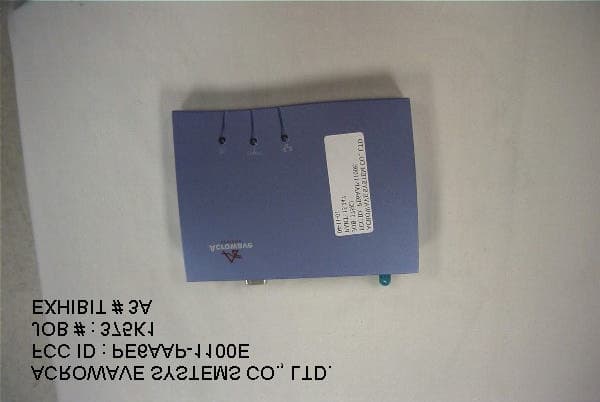
Click to zoom
Application Details
- Equipment Class
- DSS - Part 15 Spread Spectrum Transmitter
- Date of Grant
- Jul 05, 2001
- Application Purpose
- Original Equipment
- Date of Application
- Jul 05, 2001
- Equipment Note
- 2.4GHz Wireless LAN
- Frequency Range
- 2400.00000000 - 2483.50000000
- Company
- Acrowave Systems Co., Ltd
- Country
- South Korea
Documents & Files

Document Text
Text extracted from the exhibit documents filed with the FCC. Open a document above to read the original.
Users Manual
AcroLAN Access Point User’s Guide Version 2000.12.10 Copyright© Acrowave Systems 2000 DOC – xxx - yyy Page 2 of 2 Contents Chapter 1 Introduction To The Wireless LAN 1.1 What’s the Wireless LAN? .......................................... 5 1.2 Wireless LAN Standard and Structure.............................. 6 Chapter 2 Setup AcroLAN Access Point ............................ 13 2.1 Before You Begin Installation .................................... .... 13 2.2 Installing The Acrowave AcroLAN AWL-1100 Series Access Point ........................................... 15 Adjust the antennas ................................................ 15 Ethernet Cable Connection ....................................... 16 Connect The Power Pack ......................................... 17 Connect Serial Cable ............................................... 18 Open Terminal Program ........................................... 19 Configuration Change .............................................. 21 2.3 Verifying the Operation of the Acrowave Access Point ..........28 Chapter 3 Access Point Management ....................................30 3.1 Starting a Configuration Tool.............................................31 Access Point Connection. ..........................................32 Access Point Configuration Window..............................33 Terminal Window for Diagnosis ...................................37 Firmware Upgrade Window ........................................38 Firmware Upgrade Via Internet ...................................39 Firmware Upgrade Via Local Disk................................41 Access Point Detail Control........................................42 3.2 Setting Bridge Mode ..................................................... 43 Chapter 4 Troubleshooting ..................................................45 AcroLAN Access Point User’s Guide Version 2000.12.10 Copyright© Acrowave Systems 2000 DOC – xxx - yyy Page 3 of 3 Appendix Appendix A Cell Planning (Radio Range) ................................... 46 Appendix B Technical Specification .......................................... 48 Appendix C Channel Allocation ................................................ 50 AcroLAN Access Point User’s Guide Version 2000.12.10 Copyright© Acrowave Systems 2000 DOC – xxx - yyy Page 4 of 4 THE SPECIFICATIONS AND INFORMATION REGARDING THE PRODUCTS IN THIS MANUAL ARE SUBJECT TO CHANGE WITHOUT NOTICE. ALL STATEMENTS, INFORMATION, AND RECOMMENDATIONS IN THIS MANUAL ARE BELIEVED TO BE ACCURATE BUT ARE PRESENTED WITHOUT WARRANTY OF ANY KIND, EXPRESS OR IMPLIED. USERS MUST TAKE FULL RESPONSIBILITY FOR THEIR APPLICATION OF ANY PRODUCTS. THE SOFTWARE LICENSE AND LIMITED WARRANTY FOR THE ACCOMPANYING PRODUCT ARE SET FORTH IN THE INFORMATION PACKET THAT SHIPPED WITH THE PRODUCT AND ARE INCORPORATED HEREIN BY THIS REFERENCE. IF YOU ARE UNABLE TO LOCATE THE SOFTWARE LICENSE OR LIMITED WARRANTY, CONTACT YOUR ACROWAVE REPRESENTATIVE FOR A COPY. The following information is for FCC compliance of Class B devices: The equipment described in this manual generates and may radiate radio-frequency energy. If it is not installed in accordance with Acrowave’s installation instructions, it may cause interference with radio and television reception. This equipment has been tested and found to comply with the limits for a Class B digital device in accordance with the specifications in part 15 of the FCC rules. These specifications are designed to provide reasonable protection against such interference in a residential installation. However, there is no guarantee that interference will not occur in a particular installation. Modifying the equipment without Acrowave’s written authorization may result in the equipment no longer complying with FCC requirements for Class A or Class B digital devices. In that event, your right to use the equipment may be limited by FCC regulations, and you may be required to correct any interference to radio or television communications at your own expense. You can determine whether your equipment is causing interference by turning it off. If the interference stops, the Acrowave equipment or one of its peripheral devices probably caused it. If the equipment causes interference to radio or television reception, try to correct the interference by using one or more of the following measures: • Turn the television or radio antenna until the interference stops. • Move the equipment to one side or the other of the television or radio. • Move the equipment farther away from the television or radio. • Plug the equipment into an outlet that is on a different circuit from the television or radio. (That is, make certain the equipment and the television or radios are on circuits controlled by different circuit breakers or fuses.) Modifications to this product not authorized by Acrowave Systems Co., Ltd. could void the FCC approval and negate your authority to operate the product. NOTWITHSTANDING ANY OTHER WARRANTY HEREIN, ALL DOCUMENT FILES AND SOFTWARE OF THESE SUPPLIERS ARE PROVIDED “AS IS” WITH ALL FAULTS. ACROWAVE AND THE ABOVE-NAMED SUPPLIERS DISCLAIM ALL WARRANTIES, AcroLAN Access Point User’s Guide Version 2000.12.10 Copyright© Acrowave Systems 2000 DOC – xxx - yyy Page 5 of 5 EXPRESSED OR IMPLIED, INCLUDING, WITHOUT LIMITATION, THOSE OF MERCHANTABILITY, FITNESS FOR A PARTICULAR PURPOSE AND NONINFRINGEMENT OR ARISING FROM A COURSE OF DEALING, USAGE, OR TRADE PRACTICE. IN NO EVENT SHALL ACROWAVE OR ITS SUPPLIERS BE LIABLE FOR ANY INDIRECT, SPECIAL, CONSEQUENTIAL, OR INCIDENTAL DAMAGES, INCLUDING, WITHOUT LIMITATION, LOST PROFITS OR LOSS OR DAMAGE TO DATA ARISING OUT OF THE USE OR INABILITY TO USE THIS MANUAL, EVEN IF ACROWAVE OR ITS SUPPLIERS HAVE BEEN ADVISED OF THE POSSIBILITY OF SUCH DAMAGES. AcroLAN, the Acrowave logo are registered trademarks of Acrowave Systems Co., Ltd. or its affiliates in the Korea, U.S. and certain other countries. All other trademarks mentioned in this document are …
Text truncated - open the document above for the full version.
Users Manual
AcroLAN Access Point User’s Guide Version 2000.12.10 Copyright© Acrowave Systems 2000 DOC – xxx - yyy Page 11 of 11 ! !! ! BSS, ESS and SS ID The basic service set (BSS) is the basic building block of WLAN network. Minimum WLAN BSS may be consist of only two stations. Using access point (AP) and network distribution systems (DS), WLAN service set can be extended arbitrary size – extended service set (ESS). Each service set has its network ID (SSID). All the service sets within an ESS network can have same service ID so that the ESS can support inter-cell ROAMING. AcroLAN Access Point User’s Guide Version 2000.12.10 Copyright© Acrowave Systems 2000 DOC – xxx - yyy Page 12 of 12 Figure 4. SSID and Roaming Backbone Network AP #`2 SS ID = Acrowave ROAMING AP #`1 SS ID = Acrowave AP #`3 SS ID = Acro ESS BSS Backbone Network Re-Configuration Required AcroLAN Access Point User’s Guide Version 2000.12.10 Copyright© Acrowave Systems 2000 DOC – xxx - yyy Page 13 of 13 Chapter 2 Setup AcroLAN Access Point 2.1 Before You Begin Installation The Acrowave AcroLAN AWL-1100 Series Access Point is a wireless LAN transceiver that can act as the center point of a stand-alone wireless LAN network or as the connection point between wireless and wired networks. In multiple installations, the roaming functionality provided by multiple Access Points allows wireless users to move freely throughout the facility while maintaining seamless, uninterrupted access to the network. The Access Point supports Access Point management software. The system settings are contained on the Access Point's firmware. Before setting up your Access Point, ask your network system administrator for the following information: ! If your network does not use a DHCP server, you need an IP (Internet Protocol) address for the Access Point. If your network uses a DHCP server, an IP address will be assigned automatically. Each station or device on your network must have a unique IP address. ! If there is some Access Points are already installed, SSID and channel allocation strategy. ! WEP key allocation Caution You should configure the Access Point before mounting it on a pole or a ceiling. Some configuration steps, such as communicating with the Access Point through a serial cable, may be difficult if the Access Point is inaccessible. Before you begin installation, make sure that you have the following items: AcroLAN Access Point User’s Guide Version 2000.12.10 Copyright© Acrowave Systems 2000 DOC – xxx - yyy Page 14 of 14 ! The Acrowave AcroLAN AWL-1100 Series Access Point ! The Access Point power supply ! The Acrowave AcroLAN AWL-1100 Series Installation CD If any of these items are missing from the package, contact your Access Point supplier. You will also need: ! A computer that is connected to the same network as the Access Point ! A 9-pin, straight-through, male-to-female serial cable AcroLAN Access Point User’s Guide Version 2000.12.10 Copyright© Acrowave Systems 2000 DOC – xxx - yyy Page 15 of 15 2.2 Installing The Acrowave AcroLAN AWL-1100 Series Access Point Follow the instructions below to install the Access Point. For maximum range, make sure the antennas on your Access Point straight up or straight down, no matter where your Access Point is mounted. If you keep your Access Point on a table or a desk, turn the antennas so they point straight up. If you mount your Access Point on a wall or a pole, turn the antennas so they are vertical, even though the Access Point is on its side. If you mount your Access Point on the ceiling, turn the antennas so they point straight down. Antenna configurations can be varied depending on the Access Point model, cell coverage or cell plan. STEP 1 Adjust the antennas AcroLAN Access Point User’s Guide Version 2000.12.10 Copyright© Acrowave Systems 2000 DOC – xxx - yyy Page 16 of 16 Connect the Ethernet cable from your wired LAN to your Access Point. Make sure the unit is not powered up when you connect your network cable. STEP 2 Ethernet Cable Connection AcroLAN Access Point User’s Guide Version 2000.12.10 Copyright© Acrowave Systems 2000 DOC – xxx - yyy Page 17 of 17 Plug the Power Pack into a wall outlet or a power strip, and plug the connector into the power receptacle on the back of the Access Point. All three indicators on top of the access point will be bright green. During normal operation, the indicators will be bright green. If the indicators does not display a solid color or blink, see the “Top Panel Indicator Descriptions” in this manual. Caution If you have already installed Acrowave AcroLAN AWL-1100 series client card, you can easily configure Access Point through air connection between your computer and Access Point. You may skip next step and go to Access Point Management section. STEP 3 Connect The Power Pack AcroLAN Access Point User’s Guide Version 2000.12.10 Copyright© Acrowave Systems 2000 DOC – xxx - yyy Page 18 of 18 If you have a DHCP server, the server automatically assigns an IP address to the Access Point when you connect it to your network. To use the Access Point’s management system, you need to find out the assigned IP address. If you have access to the DHCP server, you can look on the server to find the IP address assigned to the Access Point. If you cannot access the DHCP server, use a 9-pin, straight-through, male-to-female serial cable to connect the COM 1 or 2 port on your computer to the RS-232 on the back of the access point. After you find the assigned IP address, you can remove this cable. You might need the cable again if you need to update the Access Point’s configuration in the future. STEP 4 Connect Serial Cable AcroLAN Access Point User’s Guide Version 2000.12.10 Copyright© Acrowave Systems 2000 DOC – xxx - yyy Page 19 of 19 Open the HyperTerminal program on the workstation attached to the Access Point. These instructions describe HyperTerminal for example, but you can use any terminal- emulation program to communicate with the Access Point. This window appea…
Text truncated - open the document above for the full version.
Users Manual
AcroLAN Access Point User’s Guide Version 2000.12.10 Copyright© Acrowave Systems 2000 DOC – xxx - yyy Page 21 of 21 Type disconfig and press Enter to see current default settings of Access Point. Make a note of the SSID, Channel number and IP address. Acrowave Access Point has a default IP; 100.100.100.100 The other options that are displayed can be ignored in this chapter and there will be detail explanation next Access Point Management section Type setconfig and press Enter to change current default configuration settings. Using this command, you can change Access Point’s SSID, Channel number, IP address, MAC address and WEP key enable/disable. After type setconfig command, whenever you press Enter key, there occur changeable Access Point options and you can select or edit what you wanted. Refer the next example. STEP 5 Configuration Change AcroLAN Access Point User’s Guide Version 2000.12.10 Copyright© Acrowave Systems 2000 DOC – xxx - yyy Page 22 of 22 The SSID value is case sensitive and can enter up to 32 characters without banks. Available channel numbers varies from country. Refer to the Appendix Channel chapter. In addition to this, it there is Access Points that have already installed in the neighborhood of your Access Point, take a cautious attitude in selecting channel number. Otherwise, by selecting too close channel number with your neighbor Access Point, raise channel interference problems. This problem can degrade wireless LAN air link quality seriously. In order to avoid this problem, select a longest channel number with your neighbor Access Point. ! RETURN ! RETURN AcroLAN Access Point User’s Guide Version 2000.12.10 Copyright© Acrowave Systems 2000 DOC – xxx - yyy Page 23 of 23 If you use Acrowave AW-1100E as a normal Access Point, select ‘ 1 ’. Otherwise, you use it as a point-to-point transmission device you should select ‘ 2 ’ or ‘ 3 ’. About this usage, detail explanation will be followed next chapter. If you know what IP address should be set to your Access Point then write it in this step. Otherwise, if you do not know what IP can be used, ask for your network administrator about available IP address. In this example, the IP address 211.189.201.251 is a default IP address that is assigned by Acrowave Systems. Caution If you have a DHCP server, this step can skip . If you have a DHCP server, your Access Point’s IP address is assigned automatically. ! RETURN ! RETURN AcroLAN Access Point User’s Guide Version 2000.12.10 Copyright© Acrowave Systems 2000 DOC – xxx - yyy Page 24 of 24 WEP stands for Wired Equivalent Privacy. WEP is an encryption scheme that provides the secure wireless data communications to the users. WEP uses a 64bit-key or 128bit- key to control the network access. In order to do secure communication over the wireless LAN network, enable WEP function. If you enable WEP function, select one of four WEP default key number. You can choose any one number from 1 to 4. And then, there occur Exclude Unencrypted question. This question asks you whether you allow a client that does not use WEP function. Next question is WEP Key Generation Mode . There are two ways to generate the WEP key. One is by entering any text in the Passphrase. The other way is by entering Key value directly from the keyboard. In this case, you can insert any character string. AcroLAN Access Point User’s Guide Version 2000.12.10 Copyright© Acrowave Systems 2000 DOC – xxx - yyy Page 25 of 25 As the wireless channel is more prone to the illegal access, WEP provides the users safe wireless LAN network access. But if you enable WEP function, it will degrade transmission throughput because it take some time to encryption/decryption. These options are provided for wireless LAN expert only, so if you does not have deep information about wireless LAN air interface specifications, do not change default options. More detail information about how to change detail configuration will be explained in Access Point Management section. Until now, you have completed all the setup options. Press Enter key. On the terminal screen, options lists that you have selected will be displayed. After confirm all the changed options, if there is no change, press y , and otherwise press n . AcroLAN Access Point User’s Guide Version 2000.12.10 Copyright© Acrowave Systems 2000 DOC – xxx - yyy Page 26 of 26 If you press y then Acrowave Access Point setup configuration will be complete and the setup program will update changed configuration in the memory. Caution During updating configuration data, there can be display flash memory write error message. In this case, call for help Acrowave Access Point distributor. AcroLAN Access Point User’s Guide Version 2000.12.10 Copyright© Acrowave Systems 2000 DOC – xxx - yyy Page 27 of 27 AcroLAN Access Point User’s Guide Version 2000.12.10 Copyright© Acrowave Systems 2000 DOC – xxx - yyy Page 28 of 28 2.3 Verifying the Operation of the Acrowave Access Point The AP runs a series of self-tests on power-up and reports status using its LEDs. When power-up begins, the following occurs: a. The firmware begins running diagnostics, initializes minimal hardware. b. After the firmware completes its diagnostics and hardware initialization. The diagnostics then checks the RF module to see whether it is properly runs in the AP. And then, the firmware downloads RF module operating program. c . U pon successful completion of the diagnostics and program download, After Radio Link LED turns on and then turns off for a few seconds all the LED display steady bright. The diagnostics take approximately 30 seconds to complete after power-up. Upon successful completion of the diagnostics, the LED pattern shown in below figure is displayed. If the AP fails to display the proper LED pattern, verify that you have correctly installed the AP. If the AP still fails to display the LED pattern, refer to troubleshooting section. AcroLAN Access Point User’s Guide Version 2000.12.10 Copyright© Acrowave Systems 2…
Text truncated - open the document above for the full version.
Users Manual
AcroLAN Access Point User’s Guide Version 2000.12.10 Copyright© Acrowave Systems 2000 DOC – xxx - yyy Page 31 of 31 3.1 Starting a Configuration Tool To modify Access Point parameters after installing the Access Point, you need to use a device connected to the console port or the AcroLAN Access Point Manager. The former was explained in the above chapter. The following sections describe how to configure the Access Point using Access Point Manager tool. If you have installed the AcroLAN Access Point Manager on a computer, select: Program Files " "" " Acrowave Systems " "" " Acrowave Access Point Manager " "" " AccessPointManager.exe Or you can simply click the AccessPointManager icon on the windows screen. The program starts with the following screen. AcroLAN Access Point User’s Guide Version 2000.12.10 Copyright© Acrowave Systems 2000 DOC – xxx - yyy Page 32 of 32 All the Access Points of Acrowave Systems have the same default IP address; 211.189.201.251. If you install the Access Point for the first time, you should type Acrowave Access Point’s default IP on the above IP address input dialog box and then press CONNECT button. If the Access Point has no problem and wire/wireless link connected without problem, A dialog box pop up that the Access Point Manager program connected to the Access Point addressed by IP. Otherwise, If the Access Point Manager program cannot find the Access Point then following message is displayed and stop search process. If the Access Point connection fails, verify that you have correctly installed the AP. If the AP still fails to connect, refer to troubleshooting chapter. Access Point Connection AcroLAN Access Point User’s Guide Version 2000.12.10 Copyright© Acrowave Systems 2000 DOC – xxx - yyy Page 33 of 33 Once, the Access Point Manager program successfully connected to an Access Point, all the configuration information of it are displayed Access Point Manager program’s configuration tab window. • Type: Acrowave’s Access Point has multiple functions; Wireless LAN Access Point, Wireless LAN Bridge for point-to-point transmission. So, this dialog box displays current function mode. Default type value is Access Point mode. • IP Address: This field allows the assignment or change of the Internet Protocol (IP) address of a station. The significance of such a change depends on whether or not DHCP is enabled for the network. If DHCP is not enabled, this field is the IP address. If Access Point Configuration Window AcroLAN Access Point User’s Guide Version 2000.12.10 Copyright© Acrowave Systems 2000 DOC – xxx - yyy Page 34 of 34 DHCP is enabled, this field will only provide the IP address if no DHCP server responds with an IP address for the Access Point. Acrowave’s AcroLAN Access Point has a default IP address - 211.189.201.251 . It is highly recommended that you change the IP address from the default only if you do not use DHCP server. You should not use the default IP address except for the first Access Point setup. • SSID: The SSID is the network name for your Access Point. All Access Points on the same LAN must be set with the same SSID in order to support inter-cell roaming. If the Access Point is configured to communicate with wireless clients and the Secure Access parameter is enabled, each client must be configured with the same SSID. If Secure Access is not enabled, clients can be configured with the Access Point’s wireless network name, ANY (all uppercase), or keep the Wireless Network Name field blank. • Default Channel: The channel sets the center frequency of the Access Point. In a LAN-to-LAN configuration, the Access Points need to be set to the same channel. In a wireless client configuration with multiple Access Points, adjacent Access Points should be set to different channels that are at least 5 channels apart recommended. For example, in a configuration with 3 Access Points, set the channels to 1, 6, and 11. Note that some countries only support a limited number of channels. Refer to the Appendix Channel section. The Access Point does not allow you to set channels outside your country’s band. Wireless clients with AcroLAN PC/PCI Cards automatically switch to the Access Point’s channel when roaming between Access Points in a wireless network. • Slave Mac Address: When the Access Point functions as a wireless LAN bridge master, it can define the slave bridge’s MAC address. • Ethernet Mac Address: The Media Access Control (MAC) address is a unique serial number assigned to a device by the Acrowave Systems. • WEP: WEP stands for Wired Equivalent Privacy. WEP is an encryption scheme that AcroLAN Access Point User’s Guide Version 2000.12.10 Copyright© Acrowave Systems 2000 DOC – xxx - yyy Page 35 of 35 provides the secure wireless data communications to the users. WEP uses a 64bit-key or 128bit-key to control the network access. In order to do secure communication over the wireless LAN network, enable WEP function. Use this setting to choose whether clients must use data encryption when communicating with this Access Point. • WEP Exclude: WEP Exclude option makes the Access Point service a client that does not use WEP function. • WEP Generation: There are two ways to generate the WEP key. One is by entering any text in the Passphrase. The other way is by entering Key value directly from the keyboard. In this case, you can insert any character string. • Passphrase : This field allows you to enter any character string to generate Key value. • Key 1, 2, 3 and 4 : These fields allow you to enter the WEP keys. Type ten hexadecimal digits (any combination of 0-9, a-f, or A-F) for 64-bit WEP keys. To protect WEP key security, existing WEP keys do not appear in the entry fields. You can write over existing keys, but you cannot edit or delete them. Caution The WEP keys for your network must be set up exactly the same on your Access Points and your PC cards. The same value must be assigned to Key 1 on both the Access Point and the PC cards, the same value must …
Text truncated - open the document above for the full version.
Users Manual
AcroLAN Access Point User’s Guide Version 2000.12.10 Copyright© Acrowave Systems 2000 DOC – xxx - yyy Page 41 of 41 In order to upgrade Access Point firmware via local disk, click the Local Disk button. In order to use this option, you should have latest firmware version in your local disk already. After you click Browse button, select the firmware that you want to update. In this time, you should take special attention in opening file so that not to open wrong file or firmware version. After confirm the file name, click the Start button. The other processes from this stage are the same as those of the Internet. Firmware Upgrade Via Local Disk AcroLAN Access Point User’s Guide Version 2000.12.10 Copyright© Acrowave Systems 2000 DOC – xxx - yyy Page 42 of 42 These windows is provided for wireless LAN expert only, so if you does not have deep information about wireless LAN air interface specifications, do not change default options. More detail information about how to change detail configuration will be explained in Access Point Management section. • Beacon Period: The amount of time between beacons. • DTIM Period: This setting, always a multiple of the beacon period, determines how often the beacon contains a delivery traffic indicator message (DTIM). The traffic indicator message tells power-save clients that a packet is waiting for them. Other items will be explained later vision of this document . Access Point Detail Control AcroLAN Access Point User’s Guide Version 2000.12.10 Copyright© Acrowave Systems 2000 DOC – xxx - yyy Page 43 of 43 3.2 Setting Bridge Mode You can connect two separate LANs over a wireless link by configuring two AcroLAN Access Points to communicate with each other. This is called a LAN-to-LAN connection. Two APs in different buildings using an outdoor antenna to connect the LANs in those buildings can be deployed. To configure two APs to communicate with each other in a LAN-to-LAN configuration, perform the following tasks: 1) Get the wireless MAC address of the remote AP. You can see the wireless address via the AP Manager or console device, as described in “Access Point Configuration Window“ section. The wireless MAC address is NOT the same as the wired MAC address printed on the front of the AP. 2) Set the Bridge Mode to LAN-to-LAN, as described in above “Access Point Configuration Window section’s Type item. 3) Make sure that the APs use the same channel. To change the AP channel, see “Access Point Configuration Window“ section. The AP provides the following bridging services: • Store-and-forward capability The AP receives, checks, and transmits frames to other LANs, enabling the configuration of extended LANs. • Frame filtering based on address Using the address database and the source and destination addresses from incoming frames, the AP isolates the traffic that should not be allowed on other LANs. This action reduces the total data traffic on an extended LAN by not forwarding the packets that have local destination addresses or packets that are not allowed to forward. This increases bandwidth efficiency. AcroLAN Access Point User’s Guide Version 2000.12.10 Copyright© Acrowave Systems 2000 DOC – xxx - yyy Page 44 of 44 • Data Link layer relay The AP operates at the Data Link layer of the Open System Interconnection (OSI) model. Operation at this layer makes the AP transparent to the protocols that use the LAN connectivity service. This protocol transparency is a key factor in the extended LAN service. AcroLAN Access Point User’s Guide Version 2000.12.10 Copyright© Acrowave Systems 2000 DOC – xxx - yyy Page 45 of 45 Chapter 4 Troubleshooting T.B.D. AcroLAN Access Point User’s Guide Version 2000.12.10 Copyright© Acrowave Systems 2000 DOC – xxx - yyy Page 46 of 46 Appendix Appendix A Cell Planning (Radio Range) This section provides general guidelines on factors that influence network performance Cell Site Survey Because of differences in component configuration, placement and physical environment, every network application is a unique installation. Before installing the system, users should perform a site survey to determine the optimum utilization of networking components and to maximize range, coverage and network performance. Here are some operating and environmental conditions you should consider: • Data Rates Radio signal sensitivity and range are inversely proportional to data bit rates. The maximum radio range is achieved at the lowest workable data rate. There will be a decrease in receiver threshold sensitivity as the radio data rate increases. • Antenna Type and Placemen t (PCI card only) Proper antenna configuration is a critical factor in maximizing radio range. As a general guide, range increases in proportion to antenna height. For a detailed explanation of antenna types and configurations along with guidelines on selecting antennas for specific environments, see the documentation that comes with your antenna. • Physical Environments Clear or open areas provide better radio range than closed or filled areas. Also, the less cluttered the work environment, the greater the range. • Obstructions A physical obstruction such as metal shelving or a steel pillar can hinder the performance of the client adapter. Avoid locating the computing device in a location where there is a metal barrier between the sending and receiving antennas. AcroLAN Access Point User’s Guide Version 2000.12.10 Copyright© Acrowave Systems 2000 DOC – xxx - yyy Page 47 of 47 • Building Materials Radio penetration is greatly influenced by the building material used in construction. For example, drywall construction allows greater range than concrete blocks. Metal or steel construction is a barrier to radio signals. Enhancing Coverage The system architecture options of the wireless station and AcroLAN Access Points provide for a variety of coverage alternatives and flexibility. The system can be designed to provide a wide coverage area with minimal overlap or coverage with heavy …
Text truncated - open the document above for the full version.
Contact Information
Applicant
Hyung Yeol Yoon(Director R&D Center)
Test Firm
Timco Engineering, Inc.S Sanders
Technical Specifications
| # | Rule Parts | Frequency Range | Power Output |
|---|---|---|---|
| 1 | 15C | 2.40 GHz - 2.48 GHz | 20.00 mW |
Other Applications from Acrowave Systems Co., Ltd

PE6AVP-2000B
Feb 08, 2006IP Phone System (Handset)
Equipment Class
DTS - Digital Transmission System
PE6AVP-CRADLEAP
Feb 08, 2006IP Phone System (Base)
Equipment Class
DTS - Digital Transmission System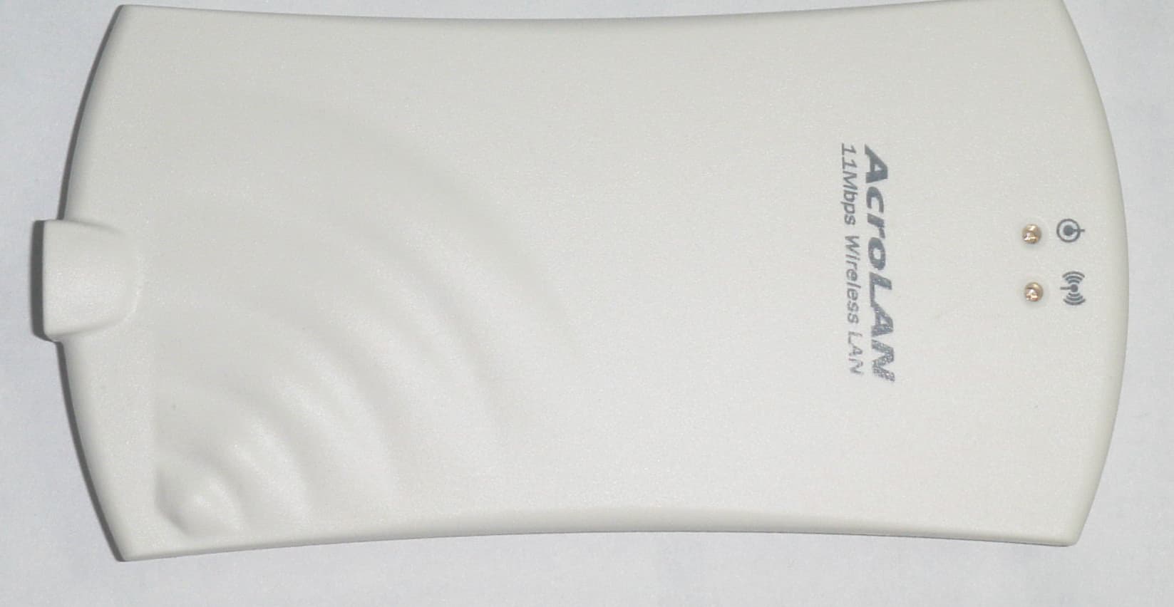
PE6AWL-1100U
Jul 28, 2002DSSS WLAN IEEE802.11b USB Card
Equipment Class
DSS - Part 15 Spread Spectrum Transmitter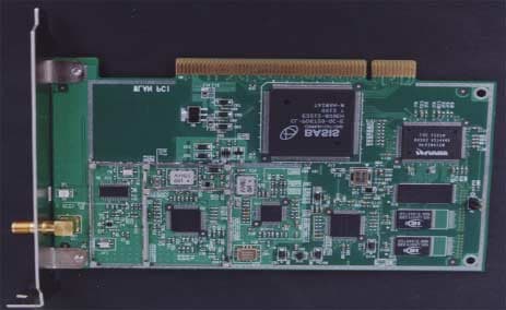
PE6AWL-1100P
May 09, 2001Wireless Lan Card
Equipment Class
DSS - Part 15 Spread Spectrum Transmitter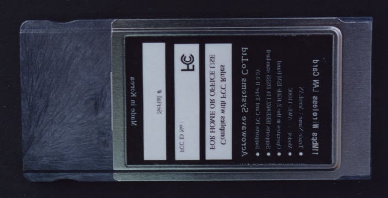
PE6AWL-1100C
Apr 03, 2001Wireless Lan Card
Equipment Class
DSS - Part 15 Spread Spectrum Transmitter