PEG362852.4GHz 40 Channel Analog Modulation Cordless Phone
Senton Enterprises Limited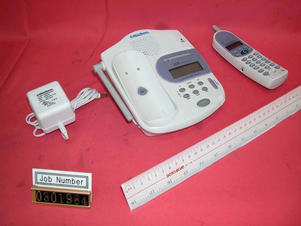
Click to zoom
Application Details
- Equipment Class
- DXT - Part 15 Low Power Transceiver, Rx Verified
- Date of Grant
- May 06, 2003
- Application Purpose
- Original Equipment
- Date of Application
- May 06, 2003
- Equipment Note
- 2.4GHz 40 Channel Analog Modulation Cordless Phone
- Frequency Range
- 2473.50000000 - 2477.40000000
- Company
- Senton Enterprises Limited
- Country
- Hong Kong
Documents & Files
Document Text
Text extracted from the exhibit documents filed with the FCC. Open a document above to read the original.
Users Manual
IMPORTANT SERVICE INFORMATION Read this manual before attempting to setup or use this instrument. It contains important information regarding safe installation and use. Keep this manual for future reference. Also save the carton, packing and proof of purchase to simplify and accelerate any needed assistance. If you need assistance or service, call (800) 888-8990 between 8:00 a.m. and 4:30 p.m. Pacific Standard Time, Monday through Friday. You can also visit our web site at http://www.nwbphones.com for technical support and information on our other products. THE EXCLAMATION POINT WITHIN EQUILATERAL TRIANGLE IS INTENDED TO ALERT THE USER TO THE PRESENCE OF IMPORTANT OPERATING MAINTENANCE(SERVICING) INSTRUCTIONS IN THE LITERATURE ACCOMPANYING THE APPLIANCE THE LIGHTING WITH ARROW HEAD SYMBOL, WITHIN AN EQUILATERAL TRIANGLE IS INTENDED TO ALERT THE USER TO THE PRESENCE OF UNINSULATED “DANGEROUS VOLTAGE” WITHIN THE PRODUCT’S ENCLOSURE THAT MAY BE OF SUFFICIENT MAGNITUDE TO CONSTITUTE A RISK OF ELECTRIC SHOCK TO PERSONS. 36285 Clock Radio/Caller ID Telephone CARTON CONTENTS • Base & Handset • Telephone Line Cord • User’s Manual • Warranty Card • Rechargeable Ni-Cad Battery • Accessory Order Form • AC Adaptor 070102A-1 2 OWNER’S MANUAL # 3628536285 ver. 070102A 070102A--11 PAGE # 2 English Version IMPORTANT SAFETY INSTRUCTIONS When using your telephone equipment, basic safety precautions should always be followed to reduce the risk of fire, electric shock, and injury to persons, including the following: 1. Read and understand all instructions. 2. Follow all warnings and instructions marked on the product. 3. Unplug this product from the wall outlet before cleaning. Do not use liquid cleaners or aerosol cleaners. Use a damp cloth for cleaning. 4. Do not use this product near water, for example, near a bathtub, wash bowl, kitchen sink, or laundry tub, in a wet basement or near a swimming pool. 5. Do not place this product on an unstable cart, stand, or table. The product may fall, causing serious damage to the product. 6. Slots and openings in the cabinet and the back or bottom are provided for ventilation, to protect it from overheating. These openings should never be blocked or covered. The openings should never be blocked by placing the product on the bed, sofa, rug, or other similar surface. This product should never be placed near or over a radiator or heat register. This product should not be placed in a built-in installation unless proper ventilation is provided. 7. This product should be operated only from the type of power source indicated on the marking label. If you are not sure of the type of power supply to your home, consult your dealer or local power company. 8. Do not allow anything to rest on the power cord. Do not locate this product where the cord will be abused by persons walking on it. 9. Do not overload wall outlets and extension cords as this can result in the risk of fire or electric shock. 10. Never push objects of any kind into this product through cabinet slots as they may touch dangerous voltage points or short out parts that could result in a risk of fire or electric shock. Never spill liquid of any kind on the product. 11. To reduce the risk of electric shock, do not disassemble this product, but take it to a qualified service contractor when some service or repair work is required. Opening or removing covers may expose you to dangerous voltages or other risks. Incorrect reassembly can cause electric shock when the appliance is subsequently used. 12. Unplug this product from the wall outlet and refer servicing to qualified service personnel under the following conditions: A. When the power supply cord or plug is damaged or frayed. B. If liquid has been spilled into the product. C. If the product has been exposed to rain or water. D. If the product does not operate normally by following the operating instructions. Adjust only those controls that are covered by the operating 3 070102A-1 OWNER’S MANUAL # 36285 ver. PAGE # 3 English Version instructions. Improper adjustments of other controls may result in damage and will often require extensive work by a qualified technician to restore the product to normal operation. E. If the product has been dropped or the cabinet has been damaged. F. If the product exhibits a distinctive change in performance. 13. Avoid using a telephone (other than a cordless type) during an electrical storm. There may be a remote risk of electric shock from lightning. 14. Do not use the telephone to report a gas leak in the vicinity of the leak. 15. Use only the power cord and batteries indicated in this manual. Do not dispose of batteries in a fire. They may explode. Check with local codes for possible special disposal instructions. SAVE THESE INSTRUCTIONS INSTALLATION PRECAUTIONS Never install telephone wiring during a lightning storm. 1. Never install telephone jacks in wet locations unless the jack is specifically designed for wet locations. 2. Never touch uninsulated telephone wires or terminals unless the telephone line has been disconnected at the network interface. 3. Use caution when installing or modifying telephone lines. MAINTENANCE 1. Use a damp cloth to clean the plastic cabinet. A mild soap will help to remove grease or oil. Never use polish, solvents, abrasives or strong detergents since these can damage the finish. 2. Your phone should be situated away from heat sources such as radiators, heaters, stoves or any other appliance that produces heat. CAUTION Risk of explosion if battery is replaced by an incorrect type. Dispose of used batteries according to the instructions , read and follow these instructions: 1. Use only the battery pack type provided with the unit, McNair SPEC-MD- N350mAh x 3, 3.6V, 350mAh, Ni-Cad. 2. Do not dispose of the battery in a fire. The cell may explode. Check with local codes for possible special disposal instructions. 3. Do not open or mutilate the battery. Released electrolyte is corrosive and may caus…
Text truncated - open the document above for the full version.
Users Manual
5 070102A-1 OWNER’S MANUAL # 36285 ver. PAGE # 5 English Version until the problem has been corrected or you are sure that the equipment is not malfunctioning. 7. This equipment may not be used on coin service provided by the telephone company. Connection to party lines is subject to state tariffs. (Contact your state public utility commission or corporation commission for information.). 8. USOC jack type is RJ11C and the compatible jack is part 68 compliance. NOTICE: If your home has specially wired alarm equipment connected to the telephone line, ensure the installation of this [equipment ID] does not disable your alarm equipment. If you have questions about what will disable alarm equipment, consult your telephone company or a qualified installer. [NOTICE: According to telephone company reports, AC electrical surges, typically resulting from lightning strikes, are very destructive to telephone equipment connected to AC power sources, To minimize damage from these types of surges, a surge arrestor is recommended. ] FCC PART 15 WARNING Changes or modifications to this unit not expressly approved by the party responsible for compliance could void the user’s authority to operate the equipment. NOTE: This equipment has been tested and found to comply with the limits for a Class B digital device ,pursuant to Part 15 of the FCC Rules. These limits are designed to provide reasonable protection against harmful interference in a residential installation. This equipment generates, uses and can radiate radio frequency energy and, if not installed and used in accordance with the instructions, may cause harmful interference to radio communications. However, there is no guarantee that interference will not occur in a particular installation. if this equipment does cause harmful interference to radio or television reception which can be determined by turning the equipment off and on. the user in encouraged to try to correct the interference by one or move of the following measures. Reorient or relocate receiving antenna. Increase the separation between the equipment and receiver. Connect the equipment in to an outlet on a circuit different form that to which the receiver is needed. Consult the dealer or an experienced radio/TV technician for help.
Block Diagram
1 1 2 2 3 3 4 4 5 5 6 6 7 7 8 8 AA BB CC DD FM FE AM FE AM IF DET FM IF DET AF POWER AMP POWER SUPPLY IC1 CXA1191S/CXA1019S BUZZCONTROL CPU EC98001 LCD 10.7MHz455KHz TITLE: MODEL : DRAW NO: FILE: SHEET : OF DWN.BY: APP.BY: CHK.BY: REV:00 DAT E: DAT E: DAT E: SENTON Xiamen NETCOM Enterprises Limited 39281/39285/36285 11 05-SEP-02 #010602C002 BLOCK DIAGRAM ANT VR1 VOLUME T2 AM IFT CF2 AM FILTER 31 2 CF1 FM FILTER 31 2 T1 AM OSC L4 AM ANT T3 FM IFT Q? NPN 32768HZ CC D BATTERY 3V R IN USE RADIO + C L? L? 500mA DC9V 1 2 D? D? D? L? FMANT L? FM OSC L?
External Photos
External photos FCC ID: PEG36285 External photos FCC ID: PEG36285
Internal Photos
Internal photos FCC ID: PEG36285 Base assembly (view 1) Base assembly (view 2) Internal photos FCC ID: PEG36285 Base Main PCB comp side (view 1) Base Main PCB comp side (view 2) Internal photos FCC ID: PEG36285 Base Main PCB solder side Radio Clock PCB comp side (view 1) Internal photos FCC ID: PEG36285 Radio Clock PCB comp side (view 2) Radio Clock PCB solder side Internal photos FCC ID: PEG36285 LCD display comp side LCD display solder side Internal photos FCC ID: PEG36285 Base LED front side Base LED rear side Internal photos FCC ID: PEG36285 Base Oscillator PCB comp side Base Oscillator PCB solder side (view 1) Internal photos FCC ID: PEG36285 Base Oscillator PCB solder side (view 2) Handset assembly Internal photos FCC ID: PEG36285 Handset Main PCB comp side (View 1) Handset Main PCB comp side (View 2) Internal photos FCC ID: PEG36285 Handset Main PCB display side Handset keypad front side Internal photos FCC ID: PEG36285 Handset keypad rear side Handset Oscillator PCB comp side Internal photos FCC ID: PEG36285 Handset Oscillator PCB solder side
Operational Description
MODEL:36285 BLOCK DIAGRAM DESCRIPTION BASE CORDLESS PHONE: (1) TRANSMISSION CIRCUIT RIGNER DETECTION : THE RING SIGNAL FROM THE LINE TO CPU VIA IC LM 324. COMMUNICATION CIRCUIT: THE COMMUNICATION SIGNAL FROM THE LINE TO CPU VIA THE TRANSFORMER .. ALL SIGNAL ARE SENT FROM CPU TO TRANSMISSION ANT VIA IC TB31261AF,TX POWERAMPLIFIER, AND DUPLEXER. (2) RECEIVING CIRCUIT THE RECEIVING ANT PICK UP THE SIGNAL AND SEND THEM TO LINE VIA DUPLEXER,RFI AMPLIFIER & MIXER,10.7MHz FILTER,IC31261AF ,IC LM324 AND TRANSFORMER . (3) THE TRANSMISSION AND RECEIVING ANT IS MADE BY 26 TWISTED COPPER WIRES,THE DIAMETER OF THE COPPER WIRE IS 0.15mm. (4) MCU (EM78911) MCU PROVIDES RING DETECTION, FSK DECODING ,CORDLESS PHONE CONTROLLER (5) CRYSTAL 32.768 KHz PROVIDES THE CLOCK FOR CPU CRYSTAL 4.0MHz PROVIDES THE CLOCK FOR IC31261AF BASE CLOCK RADIO (1) AM BAND CIRCUIT: THE AM ANT PICK-UP THE SIGNAL AND SEND IT TO IC1 (PIN ARI) VIA PVC, THE AUDIO SIGNAL FROM THE AFO PIN OF IC1 IS SENT TO DRIVE THE SPEAKER. (2) FM BAND CIRCUIT: THE FM ANT PICK-UP THE SIGNAL AND SEND IT TO IC1 (PIN FRI) VIA PVC, THE AUDIO SIGNAL FROM THE AFO PIN OF IC1 IS SENT TO DRIVE THE SPEAKER. (3) THE MCU (IC2 EC98001)PROVIDES TIME COUNTER AND LCD DRIVER, IT DRIVES THE LCD DISPLY DIRECTLY AND CONTROL THE RADIO POWER VIA Q1. (4) IC1 PROVIDES FM FE,AM FE,FM IF DET ,AM IF DET, AF POWER AMP,POWER SUPPLY. (5) THE AM ANT IS MADE BY A COIL COPPER WIRE WITH A MAGNETIC CORE. (6) THE FM ANT IS MADE BY AWG#24(THE CONNECTION WIRE OF AC ADAPTER) (7) CRYSTAL 32.768 KHz PROVIDES THE CLOCK FOR CPU EC98001. HANDSET: (1) TRAMSMISSION CIRCUIT COMMUNICATION: THE MICROPHONE PICK UP THE VOICE SIGNAL AND SEND THEM TO ANT VIA IC TB31261AF,TX POWER AMPLIFIER AND DUPLEXER. DTMF/DATA: THE KEYBOARD IS CONSISTED OF 23 KEYS, DTMF & THE DATA ARE CONTROLED BY THE CORRESPONDING KEY WHICH CONNECT TO CPU.THE CPU SEND THE SIGNAL TO ANT VIA IC TB31261AF,TX POWER AMPLIFIER AND DUPLEXER. (2) RECEIVING CIRCUIT COMMUNICATION: RECEIVING ANT PICK UP THE SIGNAL AND SEND THEM TO RECEIVER VIA DUPLEXER,RFI AMPLIFIER&MIXER, 10.7MHz FILTER, AND IC TB31261AF (3) THE TRANSMISSION AND RECEIVING ANT IS MADE BY 26 TWISTED COPPER WIRES,THE DIAMETER OF THE COPPER WIRE IS 0.15mm. (4) MCU PROVIDES KEY BOARD SCANNING, LCD DRIVER, DIALER&CORDLESS PHONE CONTROLLER. (5) CRYSTAL 32.768KHz PROVIDES THE CLOCK FOR CPU. CRYSTAL 4.0MHz PROVIDES THE CLOCK FOR ICTB31261AF. 36285 Frequency table Channel Base TX (MHz) Handset TX (MHz) 0 2401.000000 2473.500000 1 2401.100000 2473.600000 2 2401.200000 2473.700000 3 2401.300000 2473.800000 4 2401.400000 2473.900000 5 2401.500000 2474.000000 6 2401.600000 2474.100000 7 2401.700000 2474.200000 8 2401.800000 2474.300000 9 2401.900000 2474.400000 10 2402.000000 2474.500000 11 2402.100000 2474.600000 12 2402.200000 2474.700000 13 2402.300000 2474.800000 14 2402.400000 2474.900000 15 2402.500000 2475.000000 16 2402.600000 2475.100000 17 2402.700000 2475.200000 18 2402.800000 2475.300000 19 2402.900000 2475.400000 20 2403.000000 2475.500000 21 2403.100000 2475.600000 22 2403.200000 2475.700000 23 2403.300000 2475.800000 24 2403.400000 2475.900000 25 2403.500000 2476.000000 26 2403.600000 2476.100000 27 2403.700000 2476.200000 28 2403.800000 2476.300000 29 2403.900000 2476.400000 30 2404.000000 2476.500000 31 2404.100000 2476.600000 32 2404.200000 2476.700000 33 2404.300000 2476.800000 34 2404.400000 2476.900000 35 2404.500000 2477.000000 36 2404.600000 2477.100000 37 2404.700000 2477.200000 38 2404.800000 2477.300000 39 2404.900000 2477.400000
Schematics
1 1 2 2 3 3 4 4 5 5 6 6 7 7 8 8 AA BB CC DD SERVICING INSTRUCTIONS 1.UNPLUG BEFORE SERVICINS 2.REPLACE CRITICAL COMPONENTS ! WITH MANUFACTURER RECOMMENDED 3.CHECK WITH OHM METER FOR INFINITY FROM AC PLUG BLADES TO ALL EXPOSED METALLIC PARTS BEFORE RETURNING TO USER. PARTS NOTES: IN OHM, K=1000 OHM. ABOVE 1 ARE IN PF BELOW 1 ARE uF(1uF=10000000pF) UNLESS OTHERWISE SPECIFIED 3.UNLESS OTHERWISE NOTED, ALL RESISTORS ARE 1/4WATT CARBON 5 % TOLERANCE. 1.ALL RESISTANSE VALUES ARE 2.ALL CAPACITANCE VALUES TITLE: MODEL: DRAW NO: FILE: SHEET: OF DWN.BY: APP.BY: CHK.BY: REV:00 DATE: DATE: DATE: SENTON Xiamen NETCOM Enterprises Limited 39281/39285/36285 11 09-JULY-02 #020709C001 CLOCK RADIO CIRCUIT ANT 229CUSA0 C1 30p C2 30p L1 4.5T C3 30p C11 203 R2 2K2 R3 330 R4 1K LED1 RED + C12 4.7u + C13 10u + C18 10u + C19 470u C20 104 C21 104 SP.K 8 OHM R7 100K + C25 4u7 + C27 4.7u Q1 8050D D1 + C5 10u R1 100K R8 56 + C22 220u T3 F-05 T2 A-01 C26 103 R11 10 1/2 W C4 103 C10 10p T1 MO-03 CF2 10.7MHz 31 2 L2 3.5T TC101b TC101a VC101a AM COIL L4 L3 2.5T TC101cVC101c VC101d L5 19.5T VC101b TC101d C8 3p R5 100K R6 100K C24 103 IC1 CXA1191S/CXA1019S GND 1 GND 2 FD 3 NF 4 VO L 5 AO 6 AFC 7 FO 8 ROUT 9 FR 10 ARI 11 NC 12 FRI 13 REG 14 AIFI 17 FIFI 18 NC 19 TM T 20 IFG 21 AFC 22 AG C 23 DO 24 AFI 25 RF 26 VCC 27 AFO 28 GND 29 GND 30 IFO 15 BS 16 C6 22p C7 22p C9 120p ZD1 5.6V R9 1K C17 202 C14 103 + C23 4.7u + C15 1u + C16 0.22u MODE FM AM ON PM OFF MUTE BUZZ AL1 AL2 MUSIC 12:08 AM L? LCD C3 1 C2 2 C1 3 C0 4 S0 5 S1 6 S2 7 S3 8 S4 9 S5 10 S6 11 S7 12 S8 13 S9 14 3V BATTERY Q2 9014 D3 1N4148 R10 68K D4 1N4148 MU TE SNOOZE ALARM TIME UP DOWN SLEEP D13 1N4148 D11 D10 D2 1N4007 D14 1N4148 D15 1N4148 R15 10 R23 470 R22 470 Q3 9014 ZD2 3.6V + C40 10uF C37 104 C38 104 C35 15p C34 15p C39 104 C36 104 Y1 32.768KHz C28 104 C33 104 R24 470 R25 470 R26 1K R21 10K D9 1N60 D16 1N4148 FUNCTION ALAT OFF ON LED2 GREENx4 LED4LED5 Q5 8050D R18 1.5M R20 470K R16 1K Q4 9014 + C41 220uF JACK TO.DC 12 VOLUME CF1 455KHz 31 2 R19 330K + C29 470uF LED3 D8 1N60 D12 1N4148x3 L6 19.5T L7 2.2uH L8 2.2uH R17 470 R28 5.6M R29 2M R27 1M Q7 9014C Q6 9014C IC2 EC98001 VSS 1 COM3 2 COM2 3 COM1 4 COM0 5 SEG0 6 SEG1 7 SEG2 8 SEG3 9 SEG4 10 SEG 5 11 SEG 6 12 SEG7 13 SEG 8 14 SEG 9 15 SEG10 16 SEG11 17 SEG12 18 SEG13 19 SEG14 20 SEG15 21 SEG16 22 SEG17 23 SEG18 24 SEG19 25 SEG20 26 SEG21 27 SEG22 28 SEG23 29 VDD3 30 VDD2 31 VDD1 32 DH2 33 DH1 34 VDD 35 Xout 36 Xin 37 RES 38 MFP 39 RA0 40 RA1 41 RA2 42 RA3 43 RB0 44 RB1 45 RB2 46 RB3 47 RC0 48 RC1 49 RC2 50 RC3 51 R30 27 TP1 TP2 TP3 TP4 TP5 235CUSI0.sch-1 - Sat Feb 15 13:34:41 2003 334CUSK0.sch-1 - Sat Feb 15 13:42:33 2003
Test Report
• The test results reported in this report shall refer only to the sample actually tested and shall not refer or be deemed to refer to bulk from which such a sample may be said to have been obtained. • This report shall not be reproduced except in full without prior authorization form Intertek Testing Services Limited FCC ID: PEG36285 Intertek Testing Services Hong Kong Ltd. 2/F., Garment Centre, 576 Castle Peak Road, Kowloon, Hong Kong. Tel: (852) 2173 8888 Fax: (852) 2741 1693 Senton Enterprises Limited Application For Certification 2.4GHz 40 Channel Analog Modulation Cordless Phone with Caller ID and Alarm Clock Radio (FCC ID: PEG36285) WO# 03019841 TL/Ann Choy March 22, 2003 INTERTEK TESTING SERVICES FCC ID: PEG36285 i LIST OF EXHIBITS INTRODUCTION EXHIBIT 1:General Description EXHIBIT 2:System Test Configuration EXHIBIT 3:Emission Results EXHIBIT 4:Equipment Photographs EXHIBIT 5:Product Labelling EXHIBIT 6:Technical Specifications EXHIBIT 7:Instruction Manual EXHIBIT 8:Security Code Information INTERTEK TESTING SERVICES FCC ID: PEG36285 ii MEASUREMENT/TECHNICAL REPORT Senton Enterprises Limited - MODEL: 36285 FCC ID: PEG36285 This report concerns (check one:) Original Grant X Class II Change Equipment Type : Cordless Telephone (example : computer, modem, transmitter, etc.) Deferred grant requested per 47 CFR 0.457(d)(1)(ii)?Yes No X If yes, defer until : date Company Name agrees to notify the Commission by: date of the intended date of announcement of the product so that the grant can be issued on that date. Transition Rules Request per 15.37 ?Yes No X If no, assumed Part 15, Subpart C for intentional radiator - the new 47 CFR [08-20-02 Edition] Provision. Report prepared by:Tommy Leung Intertek Testing Services. 2/F., Garment Centre, 576 Castle Peak Road, Kowloon, Hong Kong. Phone :852-2173-8538 Fax:852-2741-1693 INTERTEK TESTING SERVICES FCC ID: PEG36285 iii Table of Contents 1.0General Description.........................................................................................................2 1.1 Product Description......................................................................................................2 1.2 Related Submittal(s) Grants...........................................................................................3 1.3 Test Methodology.........................................................................................................3 1.4 Test Facility..................................................................................................................3 2.0System Test Configuration..............................................................................................5 2.1 Justification...................................................................................................................5 2.2 EUT Exercising Software..............................................................................................5 2.3 Support Equipment List and Description........................................................................6 2.4 Measurement Uncertainty..............................................................................................7 2.5 Equipment Modification.................................................................................................7 3.0Emission Results..............................................................................................................9 3.1 Field Strength Calculation............................................................................................10 3.2 Radiated Emission Configuration Photograph - Base Unit.............................................11 3.3 Radiated Emission Data - Base Unit............................................................................12 3.4 Radiated Emission Configuration Photograph - Handset...............................................15 3.5 Radiated Emission Data - Handset...............................................................................16 3.6 Radiated Emission on the bandedge.............................................................................19 3.7 Line Conducted Configuration Photograph - Base Unit................................................21 3.8 Line Conducted Emission Data - Base Unit..................................................................22 4.0Equipment Photographs.................................................................................................25 5.0Product Labelling...........................................................................................................27 6.0Technical Specifications.................................................................................................29 7.0Instruction Manual.........................................................................................................31 8.0Security Code Information.............................................................................................33 INTERTEK TESTING SERVICES FCC ID: PEG36285 iv List of attached file Exhibit typeFile Descriptionfilename Test ReportTest Reportreport.pdf Operation DescriptionTechnical Descriptiondescri.pdf Test Setup PhotoRadiated Emission for Baseconfig photos.doc Test Setup PhotoRadiated Emission for Handsetconfig photos.doc Test ReportEmission Plotemission.pdf Test Setup PhotoConducted Emissionconfig photos.doc Test ReportConducted Emission Test Resultconduct.pdf External PhotoExternal Photoexternal photos.doc Internal PhotoInternal Photointernal photos.doc Block DiagramBlock Diagramblock.pdf SchematicsCircuit Diagramcircuit.pdf ID Label/LocationLabel Artwork and Locationlabel.pdf User ManualUser Manualmanual.pdf User ManualFCC Informationfcc information.pdf INTERTEK TESTING SERVICES FCC ID: PEG36285 1 EXHIBIT 1 GENERAL DESCRIPTION INTERTEK TESTING SERVICES FCC ID: PEG36285 2 1.0General Description 1.1Product Description The 36285 is a 2.4GHz 40 Channel Analog Modulation Cordless Phone with Caller ID and Alarm Clock Radio…
Text truncated - open the document above for the full version.
Test Report
Intertek Testing Services ETL SEMKO Report No.:03019841 Talk Mode Ctrl No.:N/A PAGE 1 Tested By:Hong, Report No.:03019841 Scan Settings (1 Range) |--------- Frequencies -----------||----------- Receiver Settings ------------| Start Stop Step IF BW Detector M-Time Atten Preamp OpRge 150k 30M 5k 10k PK+AV 10ms AUTO LN OFF 60dB Final Measurement: x QP / + AV Meas Time: 1 s Subranges: 16 Acc Margin: 20dB Transducer No. Start Stop Name 21 9k 30M EW0698 0 10 20 30 40 50 60 70 80 90 dBuV 100 0.15 MHz 30110 F15Q F15A Intertek Testing Services ETL SEMKO Report No.:03019841 Talk Mode Ctrl No.:N/A Tested By:Hong, Report No.:03019841 Scan Settings (1 Range) |--------- Frequencies -----------||----------- Receiver Settings ------------| Start Stop Step IF BW Detector M-Time Atten Preamp OpRge 150k 30M 5k 10k PK+AV 10ms AUTO LN OFF 60dB Final Measurement Results: no Results
Test Setup Photos
The Worst Case Configuration Photographs FCC ID: PEG36285 Radiated Emission – Base Front View Rear View The Worst Case Configuration Photographs FCC ID: PEG36285 Radiated Emission – Handset Front View Rear View The Worst Case Configuration Photographs FCC ID: PEG36285 Conducted Emission Front View Rear View The Worst Case Configuration Photographs FCC ID: PEG36285 Conducted Emission Side View
Test Setup Photos
The Worst Case Configuration Photographs FCC ID: PEG36285 Radiated Emission – Base Front View Rear View The Worst Case Configuration Photographs FCC ID: PEG36285 Radiated Emission – Handset Front View Rear View The Worst Case Configuration Photographs FCC ID: PEG36285 Conducted Emission Front View Rear View The Worst Case Configuration Photographs FCC ID: PEG36285 Conducted Emission Side View
Contact Information
Applicant
Wan Cheuk Man(Engineering Manager)
Technical Contact
Intertek Testing Services Hong Kong Ltd.Tommy Leung
[email protected]852-2173-8538
2/F., Garment Centre, · Kowloon, · Hong Kong
Non-Technical Contact
Intertek Testing Services Hong Kong Ltd.Tommy Leung
[email protected]852-2173-8538
Test Firm
Intertek Testing Services Hong KongBilly Chow
Technical Specifications
| # | Rule Parts | Frequency Range | Power Output |
|---|---|---|---|
| 2 | 15C | 2.47 GHz - 2.48 GHz | - |
Other Applications from Senton Enterprises Limited
PEG36007
Jul 17, 2006Cordless Telephone System
Equipment Class
DXX - Part 15 Low Power Communication Device Transmitter
PEG36028
Mar 27, 2006Part 15 Cordless Telephone System
Equipment Class
DXX - Part 15 Low Power Communication Device Transmitter
PEG36077
Mar 26, 2006PART 15 CORDLESS TELEPHONE SYSTEM
Equipment Class
DXX - Part 15 Low Power Communication Device Transmitter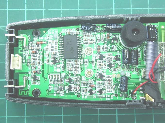
PEG36207
Mar 23, 2006PART 15 CORDLESS TELEPHONE SYSTEM
Equipment Class
DXX - Part 15 Low Power Communication Device Transmitter
PEG36271
Mar 22, 2006PART 15 CORDLESS TELEPHONE SYSTEM
Equipment Class
DXX - Part 15 Low Power Communication Device Transmitter