PFJCLNFIA15001CLN-ILB Ballast
Robert Bosch Corporation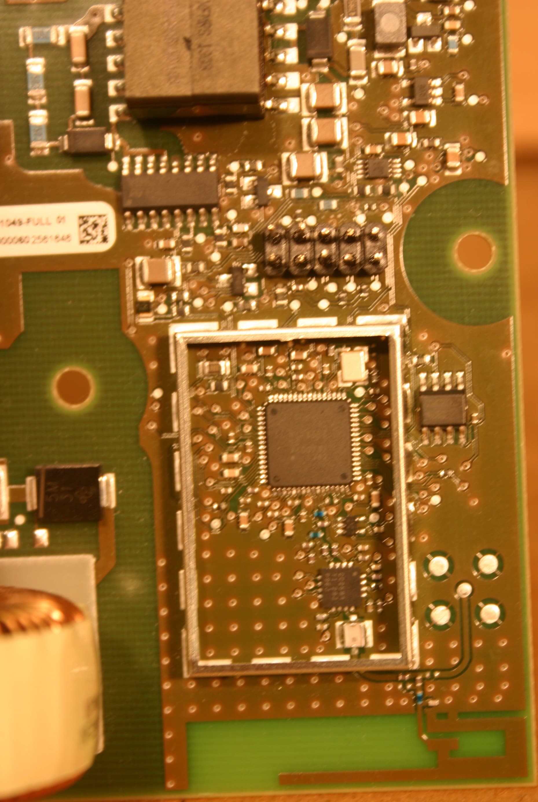
Click to zoom
Application Details
- Equipment Class
- DSS - Part 15 Spread Spectrum Transmitter
- Date of Grant
- Nov 24, 2013
- Application Purpose
- Original Equipment
- Date of Application
- Nov 24, 2013
- Equipment Note
- CLN-ILB Ballast
- Frequency Range
- 2405.50000000 - 2480.35000000
- Company
- Robert Bosch Corporation
- Country
- United States
Documents & Files
Document Text
Text extracted from the exhibit documents filed with the FCC. Open a document above to read the original.
Users Manual
AE/EME1-NA | 6/28/2013 | © 2013 Robert Bosch LLC and affiliates. All rights reserved. CLN ILB Full Spectrum Regulatory Requirements Automotive Electronics 1 Requirement 1 FSS external label must be same as Bosch label (submitted to FCC & IC) FCC ID: PFJCLNFIA15001 IC ID: 909C-CLNFIA15000 AE/EME1-NA | 6/28/2013 | © 2013 Robert Bosch LLC and affiliates. All rights reserved. CLN ILB Full Spectrum Regulatory Requirements Automotive Electronics 2 Requirement 2 Must be included in Full Spectrum User Manuals. “Changes or modifications not expressly approved by the manufacturer could void the user’s authority to operate the equipment”. AE/EME1-NA | 6/28/2013 | © 2013 Robert Bosch LLC and affiliates. All rights reserved. CLN ILB Full Spectrum Regulatory Requirements Automotive Electronics 3 Requirement 3 Full Spectrum User Manuals must include this verbiage NOTE: This equipment has been tested and found to comply with the limits for a Class A digital device, pursuant to part 15 of the FCC Rules. These limits are designed to provide reasonable protection against harmful interference when the equipment is operated in a commercial environment. This equipment generates, uses, and can radiate radio frequency energy and, if not installed and used in accordance with the instruction manual, may cause harmful interference to radio communications. Operation of this equipment in a residential area is likely to cause harmful interference in which case the user will be required to correct the interference at his own expense. AE/EME1-NA | 6/28/2013 | © 2013 Robert Bosch LLC and affiliates. All rights reserved. CLN ILB Full Spectrum Regulatory Requirements Automotive Electronics 4 Requirement 4 Full Spectrum User Manuals must include this verbiage. "WARNING: To satisfy FCC RF exposure requirements for mobile transmitting devices, a separation distance of 20cm or more should be maintained between the antenna of this device and persons during operation. To ensure compliance, operations at closer distances than this are not recommended." AE/EME1-NA | 6/28/2013 | © 2013 Robert Bosch LLC and affiliates. All rights reserved. CLN ILB Full Spectrum Regulatory Requirements Automotive Electronics 5 Requirement 5 Full Spectrum User Manuals must include this verbiage. Manufacturers of RF lighting devices must provide an advisory statement, either on the product packaging or with other user documentation, similar to the following: This product may cause interference to radio equipment and should not be installed near maritime safety communications equipment or other critical navigation or communication equipment operating between 0.45- 30 MHz. Variations of this language are permitted provided all the points of the statement are addressed and may be presented in any legible font or text style. AE/EME1-NA | 6/28/2013 | © 2013 Robert Bosch LLC and affiliates. All rights reserved. CLN ILB Full Spectrum Regulatory Requirements Automotive Electronics 6 Requirement 6 User manuals for transmitters shall display the following notice in a conspicuous location: Full Spectrum User Manuals must include this verbiage. Especially important if an external antenna connector is provided at a later date. “Under Industry Canada regulation, this radio transmitter may only operate using an antenna of a type and maximum (or lesser) gain approved for the transmitter by Industry Canada. To reduce potential radio interference to other users, the antenna type and its gain should be so chosen that the equivalent isotropically radiated power (e.r.i.p.) is not more than necessary for successful communication. AE/EME1-NA | 6/28/2013 | © 2013 Robert Bosch LLC and affiliates. All rights reserved. CLN ILB Full Spectrum Regulatory Requirements Automotive Electronics 7 Requirement 7 Full Spectrum User Manuals must include this verbiage. Especially important if an external antenna connector is provided at a later date. “This radio transmitter (identify the device by certification number, or model number if Category II) has been approved by Industry Canada to operate with the antenna types listed below with the maximum permissible gain and required antenna impedance for each antenna type indicated. Antenna types not included in this list, having a gain greater than the maximum gain indicated for that type, are strictly prohibited for use with this device”. AE/EME1-NA | 6/28/2013 | © 2013 Robert Bosch LLC and affiliates. All rights reserved. CLN ILB Full Spectrum Regulatory Requirements Automotive Electronics 8 Requirement 8 Full Spectrum User Manuals must include this verbiage. Especially important if an external antenna connector is provided at a later date. “This device complies with Industry Canada license-exempt RSS standard(s). Operation is subject to the following two conditions: (1) this device may not cause interference, and (2) this device must accept any interference, including interference that may cause undesired operation of the device”. AE/EME1-NA | 6/28/2013 | © 2013 Robert Bosch LLC and affiliates. All rights reserved. CLN ILB Full Spectrum Regulatory Requirements Automotive Electronics 9 Requirement 9 ***The following statement must appear in the manual for the device** Full Spectrum User Manuals must include this verbiage. “The installer of this radio equipment must ensure that the antenna is located or pointed such that it does not emit RF field in excess of Health Canada limits for the general population; consult Safety Code 6, obtainable from Heath Canada’s website www.hc-sc.gc.ca/rpb.” AE/EME1-NA | 6/28/2013 | © 2013 Robert Bosch LLC and affiliates. All rights reserved. CLN ILB Full Spectrum Regulatory Requirements Automotive Electronics 10 Backup Documentation – FCC 1 Items 7 and 8: FCC ID Label and Location This document can be a photo or drawing showing the identification label clearly (you must be able to see the FCC ID number), and the location on the device. These may be submitted as one document demonstrating b…
Text truncated - open the document above for the full version.
Cover Letter(s)
Page 1 of 1 FCC ID: PFJCLNFIA15001 IC ID: 909C-CLNFIA15000 CT Project: P1310002 From: Chris Harvey – Technical Reviewer Date: 10/14/13 1. Please provide antenna specification exhibit which includes antenna gains along associated frequencies and highlighted the peak gain of the antenna. CT - Corrected 2. Please provide the photos with RF shield uncovered and indicate the actual antenna location on the circuit board in “External and Internal Photos” exhibit. CT - Corrected 3. In “Test Setup Photo” exhibit, the actual tested device was not visible due to enclosure. Please show open view of device with the external enclose CT – The Manufacturer provided case is necessary for safety during testing. The protective case will be installed in final operation and it is felt the provided pictures adequately show the test setup. 4. Please state the operational frequency ranges in “Block Diagram” exhibits. CT - Corrected 5. The 2.4GHz Zigbee radio function was not clearly described in “Theory of Operation” exhibit, for instance, operational frequencies/Range, the types of modulations, channelization, transmit powers with power tolerances, and so forth. Please provide details. CT - Corrected 6. At the page 4 of “Schematic” exhibit shows “Ext Antenna (SMA)” on the drawing. Please verify whether is existed on the device. If it is correct, please indicate the “Ext Antenna (SMA)” on the photo exhibit. Or, provide right schematic diagram if it is incorrect. CT - Corrected 7. Please draw “Specification limit” lines on the graphs from the pages 11 to 20 in “Test Report”. CT – “Specification limit” lines are not required. Data is reported in tabular form and associated plots are for reference only. Response by: Alex Macon Submitted by: Jennifer Sanchez Date: 11/1/13
Cover Letter(s)
Page 1 of 1 FCC ID: PFJCLNFIA15001 IC ID: 909C-CLNFIA15000 CT Project: P1310002 From: Chris Harvey – Technical Reviewer Date: 11/4/13 1. . Information has been provided. But, the gain unit was not specificed such as “dBi” or “dBd”. Also, the antenna gains within “Antenna App Note swru120b(+3.3 db)” and “Test Report_p1310002_FCC_Part 1.1310_Rev 1.0(2.0 dBi)” exhibits are not same. Please verify and correct as necessary CT – The Test Report p1310002_FCC_Part 1.310_Rev 2.0 has been corrected to reflect the 3.3 dBi gain that is listed in the Antenna App Note. On page 12 the chart vertical axis is listed as “Relative output power” and therefore is dBi. 2. The 2.4GHz Zigbee radio function was not clearly described in “Theory of Operation” exhibit, for instance, operational frequencies/Range, the types of modulations, channelization, transmit powers with power tolerances, and so forth. Please provide details. CT – Corrected Document – Refer to revised Theory of Operation exhibit. 3. At the page 4 of “Schematic” exhibit shows “Ext Antenna (SMA)” on the drawing. Please verify whether is existed on the device. If it is correct, please indicate the “Ext Antenna (SMA)” on the photo exhibit. Or, provide right schematic diagram if it is incorrect. CT – Attached antenna has not been implemented at this time and is reserved for a later date. Response by: Alex Macon Submitted by: Jennifer Sanchez Date: 11/7/13
External Photos
Page 1 of 5 Internal Photos: FCC ID: PFJCLNFIA15001 IC: 909C-CLNFIA15000 70W_Back 70W_Top Page 2 of 5 70W_Front 150W_Back Page 3 of 5 150W_Front 150W_Top Page 4 of 5 Toroid_Back Toroid_Front Page 5 of 5 Toriod_Top
ID Label/Location Info
Ind. Change/Aend. YYYYMMDD Drawn/Gez. Checked/Gepr. Releas./Freig. BWN Resp. dept./Verantw. Abt. Add. info./Zus. Info. Size/Gst. Missed details/Fehlende Angaben Treatment/ Behandlung Mat./Stoff From/Aus Repl. for Doc.type Sheet/Bl. Ind. DP/TD Repl. by Format MNR Scale/M.stab Mat.meets/Stoffe s Crit. P. Lang./Spr. Wght./Gew. Syst. D C B E F 4 3 2 1 5 6 9 8 © Robert Bosch GmbH. Alle Rechte vorbehalten, auch bzgl. jeder Verfuegung, Verwertung, Reproduktion, Bearbeitung,Weitergabe sowie für den Fall von Schutzrechtsanmeldungen. © Robert Bosch GmbH. All rights reserved, also regarding any disposal, exploitation, reproduction, editing, distribution, as well as in the event of applications for industrial property rights. 7 10 11 12 4 3 2 1 5 6 9 8 7 10 11 12 A G H D C B A E F G H 3007 10 32 10 3.4 6 8.6 VARIANTS PART NUMBERS CLN ILB 70W ACCLN ILB 150W AC (W/Torroid) CLN ILB 150W AC (W/E-Core) CLN ILB 300W AC CLN ILB 300W DC FULLBASEFULLBASEFULLBASEFULLBASEFULLBASE TLAF OOH J01 150F 00H J01 166F 00H J01 049 F 00H J01 175 F 00H J01 144 F 00H J01 167 F 00H J01 147 F 00H J01 168 F 00H J01 149 F 00H J01 169 FCC IDPFJ-CLNFIA07001PFJCLNFIA15001 PFJ-CLNFIA15001 PFJ-CLNFIA30001 PFJ-CLNFID30001 IC ID909C-CLNFIA07001909C-CLNFIA15000 909C-CLNFIA15000 909C-CLNFIA30000 909C-CLNFID30000 01 6002JC229320130813ftk2fh810 ENTWICKLUNG 00 F00HJ0104920130312ftk2fh810 ENTWICKLUNG -- -- -- -- en/de-- MARKING PLATE TYPENSCHILD 1/1 -- 3:1DRW6 002 JV0 520000 01A2 N 2580-1PE TEMPLATE-D * FIELD 1 FCC ID 18 CHARACTERS INCLUDING SPACES, ACCORDING TO BOSCH NORM N41A A4, TYPE D, SCALE 1.8 X 1.20 FIELD 2 MAC ID 20 CHARACTERS INCLUDING SPACES, ACCORDING TO BOSCH NORM N41A A4, TYPE D, SCALE 1.8 X 1.20 * FIELD 3 IC ID: 16 CHARACTERS INCLUDING SPACES, ACCORDING TO BOSCH NORM N41A A4, TYPE D, SCALE 1.8 X 1.20 * FIELD 4 FCC SYMBOL, LETTER HEIGHT 4.0mm. BOLD FONT. * FIELDS ARE NOT CHANGEABLE (FIXED) SEE TABLE 1 LABELING FIELD: SPECIFICATION OF REQUIRED SPACE INCLUSIVE DESCENDER ACCORDING MANUFACTURER OF PRINTER. IF IT ISN'T SPECIFIED SEPERATELY POSITION OF FIELD RELATES TO CAPITAL LETTERS AND NUMBERS. Fonts and geometry for the label as defined in software from Brady printer or comparable 203 dpi Tolerance: 0.15 WITHIN THE PICTURE ELEMENTS 1 TOTAL PICTURE PRIN- TER OFFSET TO EDGES TABLE 1 SCALE 3:1 SCALE 3:1 FIELD 1 FIELD 2 FIELD 4 FIELD 3
ID Label/Location Info
Ind. Change/Aend. YYYYMMDD Drawn/Gez. Checked/Gepr. Releas./Freig. BWN Resp. dept./Verantw. Abt. Add. info./Zus. Info. Size/Gst. Missed details/Fehlende Angaben Treatment/ Behandlung Mat./Stoff From/Aus Repl. for Doc.type Sheet/Bl. Ind. DP/TD Repl. by Format MNR Scale/M.stab Mat.meets/Stoffe s Crit. P. Lang./Spr. Wght./Gew. Syst. D C B E F 4 3 2 1 5 6 9 8 © Robert Bosch GmbH. Alle Rechte vorbehalten, auch bzgl. jeder Verfuegung, Verwertung, Reproduktion, Bearbeitung,Weitergabe sowie für den Fall von Schutzrechtsanmeldungen. © Robert Bosch GmbH. All rights reserved, also regarding any disposal, exploitation, reproduction, editing, distribution, as well as in the event of applications for industrial property rights. 7 10 11 12 4 3 2 1 5 6 9 8 7 10 11 12 A G H D C B A E F G H 3007 115 +2 165 +2 50.8 +2 4.1 +2 00 F00HJ0104920121030ftk2fh810 ENTWICKLUNG -- -- -- -- en/de-- PRINTED-BOARD ASSEMBLY CLN 150AC LEITERPLATTE BESTUECKT CLN 150AC 1/1 -- 1:1DRWF 00H J01 049000 00A2 N 2580-1PE TEMPLATE-D PRELIMINARY
Internal Photos
Page 1 of 5 Internal Photos: FCC ID: PFJCLNFIA15001 IC: 909C-CLNFIA15000 70W_Back 70W_Top Page 2 of 5 70W_Front 150W_Back Page 3 of 5 150W_Front 150W_Top Page 4 of 5 Toroid_Back Toroid_Front Page 5 of 5 Toriod_Top
RF Exposure Info
Design Note DN0007 2.4 GHz Inverted F Antenna By Audun Andersen Keywords • CC2400 • CC2420 • CC2430 • CC2431 • CC2500 • CC2510 • CC2511 • CC2550 • CC2520 • CC2480 • PCB Antenna • 2.4 GHz • Inverted F Antenna 1 Introduction This document describes a PCB antenna design that can be used with all 2.4 GHz transceivers and transmitters from Texas Instruments. Maximum gain is measured to be +3.3 dB and overall size requirements for this antenna are 25.7 x 7.5 mm. Thus, this is a compact, low cost and high performance antenna. SWRU120B Page 1 of 14 Design Note DN0007 Table of Contents KEYWORDS..............................................................................................................................1 1 INTRODUCTION.............................................................................................................1 2 ABBREVIATIONS...........................................................................................................2 3 DESCRIPTION OF THE INVERTED F ANTENNA DESIGN.........................................3 3.1 IMPLEMENTATION OF THE INVERTED F ANTENNA..........................................................3 4 RESULTS........................................................................................................................4 4.1 RADIATION PATTERN..................................................................................................4 4.2 REFLECTION............................................................................................................11 4.3 BANDWIDTH.............................................................................................................11 5 CONCLUSION ..............................................................................................................12 6 REFERENCES ..............................................................................................................13 7 GENERAL INFORMATION..........................................................................................14 7.1 DOCUMENT HISTORY................................................................................................14 2 Abbreviations CC2480 Z-Accel ZigBee Processor EM Evaluation Module IFA Inverted F Antenna ISM Industrial, Scientific, Medical PCB Printed Circuit Board SWRU120B Page 2 of 14 Design Note DN0007 3 Description of the Inverted F Antenna Design Since the impedance of the Inverted F Antenna is matched directly to 50 ohm no external matching components are needed. 3.1 Implementation of the Inverted F Antenna It is important to make an exact copy of the antenna dimensions to obtain optimum performance. The easiest approach to implement the antenna in a PCB CAD tool is to import the antenna layout from either a gerber or DXF file. Such files are included in CC2430DB reference design [1]. The gerber file is called “Inverted_F_Antenna.spl” and the DXF file is called “Inverted_F_Antenna.dxf”. If the antenna is implemented on a PCB that is wider than the antenna it is important to avoid placing components or having a ground plane close to the end points of the antenna. If the CAD tool being used doesn’t support import of gerber or DXF files, Figure 1 and Table 1 can be used. Figure 1. IFA Dimensions H1 5.70 mmW2 0.46 mm H2 0.74 mmL1 25.58 mm H3 1.29 mmL2 16.40 mm H4 2.21 mmL3 2.18 mm H5 0.66 mmL4 4.80 mm H6 1.21 mmL5 1.00 mm H7 0.80 mmL6 1.00 mm H8 1.80 mmL7 3.20 mm H9 0.61 mmL8 0.45 mm W1 1.21 mm Table 1. IFA Dimensions Since there is no ground plane beneath the antenna, PCB thickness will have little effect on the performance. The results presented in this design note are based on an antenna implemented on a PCB with 1 mm thickness. SWRU120B Page 3 of 14 Design Note DN0007 4 Results All results presented in this chapter are based on measurements performed with CC2430DB [1]. 4.1 Radiation Pattern Figure 2 shows how to relate all the radiation patterns to the orientation of the antenna. The radiation patterns were measured with CC2430 programmed to 0 dBm output power. XY plane XZ plane YZ plane Figure 2. How to Relate the Antenna to the Radiation Patterns SWRU120B Page 4 of 14 Design Note DN0007 Figure 3. XY Plane Vertical Polarization SWRU120B Page 5 of 14 Design Note DN0007 Figure 4. XY Plane Horizontal Polarization SWRU120B Page 6 of 14 Design Note DN0007 Figure 5. XZ Plane Vertical Polarization SWRU120B Page 7 of 14 Design Note DN0007 Figure 6. XZ Plane Horizontal Polarization SWRU120B Page 8 of 14 Design Note DN0007 Figure 7. YZ Plane Vertical Polarization SWRU120B Page 9 of 14 Design Note DN0007 Figure 8. YZ Plane Horizontal Polarization SWRU120B Page 10 of 14 Design Note DN0007 4.2 Reflection Figure 9. Measured Reflection at the Feed Point of the Antenna Figure 9 show that the IFA ensures less than 10 % reflection of the available power for a bandwidth of more than 300 MHz. A large bandwidth makes the antenna less sensitive to detuning due to plastic encapsulation or other objects in the vicinity of the antenna. 4.3 Bandwidth Another way of measuring the bandwidth after the antenna is implemented on a PCB and connected to a transmitter is to write test software that steps a carrier across the frequency band of interest. By using the “Max hold” function on a spectrum analyzer the variation in output power across frequency can easily be measured. Figure 10 shows how the output power varies on the IFA when the PCB is horizontally oriented and the receiving antenna has horizontal polarization. This measurement was not performed in an anechoic chamber thus the graph shows only the relative variation for the given frequency band. SWRU120B Page 11 of 14 Design Note DN0007 Bandwidth IFA 2.4 2.4835 -60 -50 -40 -30 -20 -10 0 2.22.32.42.52.62.72.8 Frequency [GHz] R e l a ti v e output pow e r [dB ] Output pow er Lower band edge Upper band edge Figure 10. Bandwidth of IFA 5 Conclusion The PCB antenna presented in this document performs well for all frequencies in the 2.4 GHz ISM band. Except for …
Text truncated - open the document above for the full version.
Test Report
p1310002_FCC_Part 1.1310_Rev 1.0 Page 1 of 4 Test Report Prepared for: Robert Bosch, LLC Model: CLN-ILB Ballast Description: 2.4 GHz Transmitter To FCC Part 1.1310 Date of Issue: November 4, 2013 On the behalf of the applicant: Robert Bosch, LLC 15000 North Haggerty Road Plymouth, MI 48170 Attention of: Steven Gladstein, Engineering Manager Ph: (734) 979-3035 E-Mail: [email protected] Prepared By Compliance Testing, LLC 3356 N San Marcos Pl, Suite 107 Chandler, AZ 85225-7176 (866) 311-3268 phone / (480) 926-3598 fax www.compliancetesting.com Project No: p1310002 Alex Macon Project Test Engineer This report may not be reproduced, except in full, without written permission from Compliance Testing All results contained herein relate only to the sample tested p1310002_FCC_Part 1.1310_Rev 1.0 Page 2 of 4 Test Report Revision History Revision Date Revised By Reason for Revision 1.0 September 20, 2013 Alex Macon Original Document 2.0 November 4, 2013 Alex Macon Updated numeric gain and calculation p1310002_FCC_Part 1.1310_Rev 1.0 Page 3 of 4 ILAC / A2LA Compliance Testing, LLC, has been accredited in accordance with the recognized International Standard ISO/IEC 17025:2005. This accreditation demonstrates technical competence for a defined scope and the operation of a laboratory quality management system (refer joint ISO-ILAC-IAF Communiqué dated January 2009) The tests results contained within this test report all fall within our scope of accreditation, unless noted below. Please refer to http://www.compliancetesting.com/labscope.html for current scope of accreditation. Testing Certificate Number: 2152.01 FCC OATS Reg, #933597 IC Reg. #2044A-1 Non-accredited tests contained in this report: N/A p1310002_FCC_Part 1.1310_Rev 1.0 Page 4 of 4 Description The EUT is a lighting ballast with an incorporated 2.4 GHz Zigbee transceiver. This is a mobile device used in Uncontrolled Exposure environment. Limits - Uncontrolled Exposure 47 CFR 1.1310 Table 1, (B) 0.3-1.234 MHz: Limit [mW/cm²] = 100 1.34-30 MHz: Limit [mW/cm²] = (180/f²) 30-300 MHz: Limit [mW/cm²] = 0.2 300-1500 MHz: Limit [mW/cm²] = f/1500 1500-100,000 MHz Limit [mW/cm²] = 1.0 Test Frequencies, MHz 2405.0 MHz Power, Conducted, mW (P) 39.3 mW Antenna Gain Isotropic 3.3dBi Antenna Gain Numeric (G) 2.14 Antenna Type Distance (R) 20 cm Power Density Calculations Formula = S = PG / 4πR² Power Density (S) = 0.0167 mW/cm² Limit = 1.0 mW/cm² The Power Density is below the Limit. The SAR measurement is not necessary. END OF TEST REPORT
Test Report
p1310002_FCC_15.247_DTS_Rev 1.0 Page 1 of 38 Test Report Prepared for: Robert Bosch, LLC Model: CLN-ILB Ballast Description: 2.4 GHz Transmitter To FCC Part(s) 15.247 DTS Date of Issue: September 13, 2013 On the behalf of the applicant: Robert Bosch, LLC 15000 North Haggerty Road Plymouth, MI 48170 Attention of: Steven Gladstein, Engineering Manager Ph: (734) 979-3035 E-mail: [email protected] Prepared By Compliance Testing, LLC 3356 N San Marcos Pl, Suite 107 Chandler, AZ 85225-7176 (866) 311-3268 phone / (480) 926-3598 fax www.compliancetesting.com Project No: p1310002 Alex Macon Project Test Engineer This report may not be reproduced, except in full, without written permission from Compliance Testing All results contained herein relate only to the sample tested p1310002_FCC_15.247_DTS_Rev 1.0 Page 2 of 38 Test Report Revision History Revision Date Revised By Reason for Revision 1.0 September 13, 2013 Alex Macon Original Document p1310002_FCC_15.247_DTS_Rev 1.0 Page 3 of 38 Table of Contents Description Page Standard Test Conditions Engineering Practices ................................................................................... 6 Peak Output Power ................................................................................................................................. 9 Conducted Spurious Emission .............................................................................................................. 10 Radiated Spurious Emissions ............................................................................................................... 21 Emissions at Band Edges ..................................................................................................................... 24 Occupied Bandwidth ............................................................................................................................. 26 Transmitter Power Spectral Density (PSD) .......................................................................................... 29 A/C Powerline Conducted Emission ..................................................................................................... 31 Receiver Spurious Emissions ............................................................................................................... 35 Test Equipment Utilized ........................................................................................................................ 38 p1310002_FCC_15.247_DTS_Rev 1.0 Page 4 of 38 ILAC / A2LA Compliance Testing, LLC, has been accredited in accordance with the recognized International Standard ISO/IEC 17025:2005. This accreditation demonstrates technical competence for a defined scope and the operation of a laboratory quality management system (refer joint ISO-ILAC-IAF Communiqué dated January 2009) The tests results contained within this test report all fall within our scope of accreditation, unless noted below. Please refer to http://www.compliancetesting.com/labscope.html for current scope of accreditation. Testing Certificate Number: 2152.01 FCC OATS Reg, #933597 IC Reg. #2044A-1 Non-accredited tests contained in this report: N/A p1310002_FCC_15.247_DTS_Rev 1.0 Page 5 of 38 The applicant has been cautioned as to the following 15.21 - Information to User The user’s manual or instruction manual for an intentional radiator shall caution the user that changes or modifications not expressly approved by the party responsible for compliance could void the user’s authority to operate the equipment. 15.27(a) - Special Accessories Equipment marked to a consumer must be capable of complying with the necessary regulations in the configuration in which the equipment is marketed. Where special accessories, such as shielded cables and/or special connectors are required to enable an unintentional or intentional radiator to comply with the emission limits in this part, the equipment must be marketed with, i.e. shipped and sold with, those special accessories. However, in lieu of shipping or packaging the special accessories with the unintentional or intentional radiator, the responsible party may employ other methods of ensuring that the special accessories are provided to the consumer without an additional charge. Information detailing any alternative method used to supply the special accessories for a grant of equipment authorization or retained in the verification records, as appropriate. The party responsible for the equipment, as detailed in § 2.909 of this chapter, shall ensure that these special accessories are provided with the equipment. The instruction manual for such devices shall include appropriate instructions on the first page of text concerned with the installation of the device that these special accessories must be used with the device. It is the responsibility of the user to use the needed special accessories supplied with the equipment. p1310002_FCC_15.247_DTS_Rev 1.0 Page 6 of 38 Standard Test Conditions Engineering Practices Except as noted herein, the following conditions and procedures were observed during the testing. In accordance with ANSI C63.10-2009 and unless otherwise indicated in the specific measurement results, the ambient temperature of the actual EUT was maintained within the range of 10° to 40°C (50° to 104°F) unless the particular equipment requirements specify testing over a different temperature range. Also, unless otherwise indicated, the humidity levels were in the range of 10% to 90% relative humidity. Measurement results, unless otherwise noted, are worst-case measurements. Environmental Conditions Temperature (ºC) Humidity (%) Pressure (mbar) 25.4 - 27.5 39.7 - 49.3 962.3 – 967.9 EUT Description Model: CLN-ILB Ballast Description: 2.4 GHz Transmitter Additional Information: The manufacturer provided 3 different devices tuned to low, medium and high channels. The high channel’s power was decreased in order to pass the high end restricted band specification. The manufacturer de…
Text truncated - open the document above for the full version.
Test Setup Photos
Page 1 of 4 Test Setup Photos: Conducted Emissions Page 2 of 4 Radiated Emissions Page 3 of 4 Page 4 of 4
Contact Information
Applicant
Chris Chen(Technical Project Manager)
Test Firm
Compliance Testing, LLCMichael Schafer
Technical Specifications
| # | Rule Parts | Frequency Range | Power Output |
|---|---|---|---|
| 1 | 15C | 2.41 GHz - 2.48 GHz | 39.30 mW |
Other Applications from Robert Bosch Corporation
PFJPKM250
Oct 01, 2023Master ECU BT-LE+UWB
Equipment Class
DTS - Digital Transmission System
PFJG2EX23
Aug 17, 2014RF Receiver
Equipment Class
CYY - Communications Receiver used w/Pt 15 Transmitter
PFJG2TN23
Aug 07, 2014RF Receiver
Equipment Class
CYY - Communications Receiver used w/Pt 15 Transmitter
PFJG2TN24
Aug 07, 2014RF Receiver
Equipment Class
CYY - Communications Receiver used w/Pt 15 Transmitter
PFJG2THK4
Jul 20, 2014RF Receiver
Equipment Class
CYY - Communications Receiver used w/Pt 15 Transmitter