PFJPK3R0Passkey Immobilizer
Robert Bosch Corporation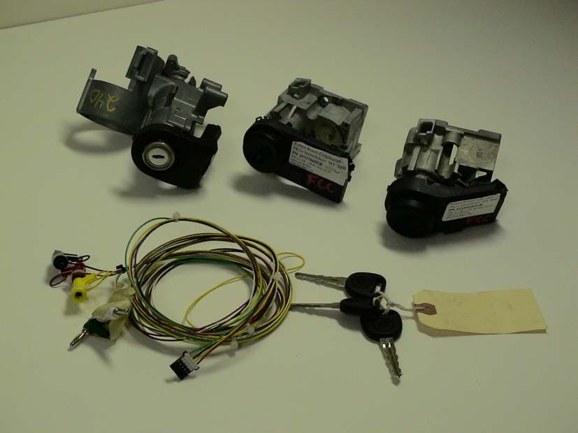
Click to zoom
Application Details
- Equipment Class
- DCD - Part 15 Low Power Transmitter Below 1705 kHz
- Date of Grant
- Nov 21, 2004
- Application Purpose
- Original Equipment
- Date of Application
- Nov 21, 2004
- Equipment Note
- Passkey Immobilizer
- Frequency Range
- 0.12500000 - 0.12500000
- Company
- Robert Bosch Corporation
- Country
- United States
Documents & Files
Document Text
Text extracted from the exhibit documents filed with the FCC. Open a document above to read the original.
Users Manual
Re: Certification for Bosch Passkey Immobilizer PN(s): 1516624GB, 10337868EB, 22719734 FCC ID: PFJPK3R0 IC: 909C-PK3R0 USER'S MANUAL INFORMATION (PRELIMINARY) The User's Manual is in preparation. The following material will be contained in the manual: FCC ID: PFJPK3R0 IC: 909C-PK3R0 This device complies with Part 15 of the FCC Rules and with RSS-210 of Industry Canada. Operation is subject to the following two conditions: (1) This device may not cause harmful interference, and (2) This device must accept any interference received, including interference that may cause undesired operation. WARNING: Changes or modifications not expressively approved by the party responsible for compliance could void the user's authority to operate the equipment. The term “IC:” before the radio certification number only signifies that Industry Canada technical specifications were met.
Block Diagram
Battery + - Pin#3/GND Pin#2/IGN Pin#1/VBAT Pin#5/GMLAN2 Pin#4/GMLAN1 5V Reg. + Reset + Low Vbat Detect Ignition Input w/ Hysterysis GMLAN Physical Layer Micro & Ext. EEPROM & 8MHz Resonator ABIC (LF ASIC) 125KHz Internal Coil PK3+ Block & Detailed Functional Diagram 33Kbs
Cover Letter(s)
Re: Certification for Bosch Passkey Immobilizer PN(s): 1516624GB, 10337868EB, 22719734 FCC ID: PFJPK3R0 IC: 909C-PK3R0 REQUEST FOR CONFIDENTIALITY Pursuant to 47 CRF 0.459, Bosch requests that a part of the subject application be held confidential. This comprises Exhibits (5) Schematics (10) Parts List (Part of Exhibit only) Bosch has spent substantial effort in developing this product and it is one of the first of its kind in industry. Having the subject information easily available to "competition" would negate the advantage they have achieved by developing this product. Not protecting the details of the design will result in financial hardship. If there are any questions regarding this request, please contact me at the above address or call 734-483-4211, fax 734-647-2106 or e-mail [email protected]. Sincerely, Valdis V. Liepa Research Scientist University of Michigan November 16, 2004 Re: Certification for Bosch Passkey Immobilizer PN(s): 1516624GB, 10337868EB, 22719734 FCC ID: PFJPK3R0 IC: 909C-PK3R0 STATEMENT OF MODIFICATIONS There were no modifications made to the DUT by this test laboratory. (Also see Section 3.1 of the attached Test Report). _____________________ Valdis V. Liepa Research Scientist Re: Certification for Bosch Passkey Immobilizer PN(s): 1516624GB, 10337868EB, 22719734 FCC ID: PFJPK3R0 IC: 909C-PK3R0 GENERAL PRODUCT INFORMATION The device, for which certification is pursued, has been designed by: Robert Bosch Corporation 38000 Hills Tech Drive Farmington Hills, MI 48331 Bill Lusa Tel: 734-484-1387 Fax: 734-484-1389 It will be manufactured by: Robert Bosch Corporation 38000 Hills Tech Drive Farmington Hills, MI 48331 Bill Lusa Tel: 734-484-1387 Fax: 734-484-1389 Canadian Contact: Scott Bernard Robert Bosch Corporation 8787 Riverside Drive East, Apt 1106 Windsor, Ontario, N8S 1G7 [email protected] Re: Certification for Bosch Passkey Immobilizer PN(s): 1516624GB, 10337868EB, 22719734 FCC ID: PFJPK3R0 IC: 909C-PK3R0 POWER OF ATTORNEY A letter granting Valdis V. Liepa the Power of Attorney is on file and can be provided when so requested.
Cover Letter(s)
November 22, 2004 RE: Robert Bosch Corporation FCC ID: PFJPK3R0 The following is in response to comments made on the above referenced Application. 1) Since all 3 have different surfaces, please provide information to show the label placement on all 3 devices. The drawings provided demonstrate the location of the ID label for all three models and should be sufficient. No additional drawings are available from the manufacturer. 2) What were the RBW settings used > 150 kHz. The report mentions 300 and 1 kHz on page 4. ANSI C63.4 requires > 9 kHz for 150 kHz – 30 MHz. Note the table mentions 9 kHz. All this appears inconsistent. Please review/correct as necessary. For radiated emission measurements on the OATS above 150 kHz, > 9KHz RBW was used per ANSI C63.4. For indoor pretest measurements (those made in the Anechoic Chamber) and outdoor radiated emission measurements below 150 KHz, the choice of RBW was made so as not to decrease the EBW (emission bandwidth) of the device. The report mentions 300Hz and 1KHz bandwidths as those used to measure the fundamental emission (which is < 150 KHz). The test report has been modified to make this clear. 3) It is uncertain if the loop antenna was rotated about the vertical axis as required by section 8.2 ANSI C63.4. The FCC expects this to be maximized during testing. As always, the loop antenna was rotated about the vertical axis and the DUT was rotated to maximize radiated emission measurements, as noted in the antenna orientation and comments section of the data table. 4) Please provide information about how the emissions on page 7 were calculated. It appears that the calculations are off by about 10 dB. It almost appears that the Ka factor may not have been included. There was a typographical error in the table. It has been fixed and a revised test report has been uploaded.
Cover Letter(s)
American Telecommunications Certification Body Inc. 6731 Whittier Ave, McLean, VA 22101 November 20, 2004 RE: Robert Bosch Corporation FCC ID: PFJPK3R0 After a review of the submitted information, I have a few comments on the above referenced Application. 1) Since all 3 have different surfaces, please provide information to show the label placement on all 3 devices. 2) What were the RBW settings used > 150 kHz. The report mentions 300 and 1 kHz on page 4. ANSI C63.4 requires > 9 kHz for 150 kHz – 30 MHz. Note the table mentions 9 kHz. All this appears inconsistent. Please review/correct as necessary. 3) It is uncertain if the loop antenna was rotated about the vertical axis as required by section 8.2 ANSI C63.4. The FCC expects this to be maximized during testing. 4) Please provide information about how the emissions on page 7 were calculated. It appears that the calculations are off by about 10 dB. It almost appears that the Ka factor may not have been included. Please review and correct as necessary. Timothy R. Johnson Examining Engineer mailto: [email protected] The items indicated above must be submitted before processing can continue on the above referenced application. Failure to provide the requested information may result in application termination. Correspondence should be considered part of the permanent submission and may be viewed from the Internet after a Grant of Equipment Authorization is issued. Please do not respond to this correspondence using the email reply button. In order for your response to be processed expeditiously, you must submit your documents through the AmericanTCB.com website. Also, please note that partial responses increase processing time and should not be submitted. Any questions about the content of this correspondence should be directed to the sender.
ID Label/Location Info
2JL03
Operational Description
Pass-Key III+ Operation Your vehicle is equipped with PASS-Key®♦III+ (Personalized Automotive Security System) theft- deterrent system. PASS-Key®♦III+ is a passive theft-deterrent system. This means you don’t have to do anything special to arm or disarm the system. It works when you insert or remove the key from the ignition. When the PASS-Key®♦III+ system senses that someone is using the wrong key, it prevents the vehicle from starting.shuts down the vehicle’s starter and fuel systems. The starter will not work and fuel will stop flowing to the engine. Anyone using a trial-and-error method to start the vehicle will be discouraged because of the high number of electrical key codes. When trying to start the vehicle if the engine does not start and the SECURITY light comes on, the key may have a damaged transponder. Turn the ignition off and try again. If the engine still does not start, and the key appears to be undamaged, try another ignition key. At this time, you may also want to check the fuse, see Fuses and Circuit Breakers . If the engine still does not start with the other key, your vehicle needs service. If your vehicle does start, the first key may be faulty. See your dealer who can service the PASS-Key®♦III+ to have a new key made. In an emergency, contact Roadside Assistance. It is possible for the PASS-Key®♦III+ decoder to “learn” the transponder value of a new or replacement key. Up to 10♦additional keys may be programmed for the vehicle. The following procedure is for programming additional keys only. If all the currently programmed keys are lost or do not operate, you must see your dealer or a locksmith who can service PASS-Key®♦III+ to have keys made and programmed to the system. See your dealer or a locksmith who can service PASS-Key®♦III+ to get a new key blank that is cut exactly as the ignition key that operates the system.
Test Report
The University of Michigan Radiation Laboratory 3228 EECS Building Ann Arbor, MI 48109-2122 Tel: (734) 764-0500 Measured Radio Frequency Emissions From Robert Bosch Corporation Transmitter PNs: 1516624GB, 10337868EB, and 22719734 Report No. 415031-226 November 22, 2004 Copyright © 2004 For: Bosch 38000 Hills Tech Drive Farmington Hills, MI 48331 Contact: Bill Lusa Tel: (734) 484-1387 Fax: 734-484-1389 Tests supervised by: Measurements made by: Joseph D Brunett Report approved by: _____________________ Valdis V. Liepa Research Scientist Summary Tests for compliance with FCC Regulations, Part 15, Subpart C, and for compliance with Industry Canada RSS-210, were performed on Bosch transmitter, PN 1516624GB, 10337868EB, 22719734. This device is subject to Rules and Regulations as a transmitter. In testing completed November 15, 2004, the device tested in the worst case met the allowed specifications for transmitter radiated emissions by 34.3 dB (see p. 7); digital emissions, Class B, were met by at least 20 dB. The conducted emissions tests do not apply, since the device is powered from a 12 VDC system. 2 1. Introduction Robert Bosch Corporation PN 1516624GB, 10337868EB, and 22719734 were tested for compliance with FCC Regulations, Part 15, adopted under Docket 87-389, April 18, 1989, and with Industry Canada RSS- 210, Issue 5, November, 2001. The tests were performed at the University of Michigan Radiation Laboratory Willow Run Test Range following the procedures described in ANSI C63.4-1992 "Methods of Measurement of Radio-Noise Emissions from Low-Voltage Electrical and Electronic Equipment in the Range of 9 kHz to 40 GHz". The Site description and attenuation characteristics of the Open Site facility are on file with FCC Laboratory, Columbia, Maryland (FCC Reg. No: 91050) and with Industry Canada, Ottawa, ON (File Ref. No: IC 2057). 2. Test Procedures and Equipment Used The pertinent test equipment commonly used in our facility for measurements is listed in Table 2.1 below. The middle column identifies the specific equipment used in these tests. Table 2.1 Test Equipment. Test Instrument Eqpt. Used Manufacturer/Model Spectrum Analyzer (0.1-1500 MHz) Hewlett-Packard, 182T/8558B Spectrum Analyzer (9kHz-22GHz) X Hewlett-Packard 8593A SN: 3107A01358 Spectrum Analyzer (9kHz-26GHz) X Hewlett-Packard 8593E, SN: 3412A01131 Spectrum Analyzer (9kHz-26GHz) Hewlett-Packard 8563E, SN: 3310A01174 Spectrum Analyzer (9kHz-40GHz) Hewlett-Packard 8564E, SN: 3745A01031 Power Meter Hewlett-Packard, 432A Power Meter Anritsu, ML4803A/MP Harmonic Mixer (26-40 GHz) Hewlett-Packard 11970A, SN: 3003A08327 Harmonic Mixer (40-60 GHz) Hewlett-Packard 11970U, SN: 2332A00500 Harmonic Mixer (75-110 GHz) Hewlett-Packard 11970W, SN: 2521A00179 Harmonic Mixer (140-220 GHz) Pacific Millimeter Prod., GMA, SN: 26 S-Band Std. Gain Horn S/A, Model SGH-2.6 C-Band Std. Gain Horn University of Michigan, NRL design XN-Band Std. Gain Horn University of Michigan, NRL design X-Band Std. Gain Horn S/A, Model 12-8.2 X-band horn (8.2- 12.4 GHz) Narda 640 X-band horn (8.2- 12.4 GHz) Scientific Atlanta , 12-8.2, SN: 730 K-band horn (18-26.5 GHz) FXR, Inc., K638KF Ka-band horn (26.5-40 GHz) FXR, Inc., U638A U-band horn (40-60 GHz) Custom Microwave, HO19 W-band horn(75-110 GHz) Custom Microwave, HO10 G-band horn (140-220 GHz) Custom Microwave, HO5R Bicone Antenna (30-250 MHz) X University of Michigan, RLBC-1 Bicone Antenna (200-1000 MHz) X University of Michigan, RLBC-2 Dipole Antenna Set (30-1000 MHz) X University of Michigan, RLDP-1,-2,-3 Dipole Antenna Set (30-1000 MHz) EMCO 2131C, SN: 992 Active Rod Antenna (30 Hz-50 MHz) EMCO 3301B, SN: 3223 Active Loop Antenna (30 Hz-50 MHz) X EMCO 6502, SN:2855 Ridge-horn Antenna (300-5000 MHz) X University of Michigan Amplifier (5-1000 MHz) X Avantek, A11-1, A25-1S Amplifier (5-4500 MHz) X Avantek Amplifier (4.5-13 GHz) Avantek, AFT-12665 Amplifier (6-16 GHz) Trek Amplifier (16-26 GHz) Avantek LISN Box University of Michigan Signal Generator Hewlett-Packard 8657B 3 3. Configurations and Identification of Device Under Test The DUT is a 125 kHz LF transmitter designed for an onboard automobile immobilizer system, and as such, it is powered from an automotive 12 VDC source. It is housed in a plastic case approximately 3 by 2 by 0.5 inches. Coil is internal. For testing, a generic harness was provided by the manufacturer. The DUT was designed and manufactured by Bosch, 38000 Hills Tech Drive, Farmington Hills, MI 48331. It is identified as: Bosch Passkey Immobilizer PN(s): 1516624GB, 10337868EB, 22719734 FCC ID: PFJPK3R0 IC: 909C-PK3R0 NOTE: All three part numbers tested contain the same PCB and antenna coil. The only difference between the models is the coil orientation with respect to the PCB and the steering column section on which they mount. 3.1 EMI Relevant Modifications No EMI Relevant Modifications were performed by this test laboratory. 4. Emission Limits 4.1 Radiated Emission Limits The DUT tested falls under the category of an Intentional Radiators and the Digital Devices, subject to Subpart C, Section 15.209; and Subpart B, Section 15.109 (transmitter generated signals excluded); and Subpart A, Section 15.33. The applicable testing frequencies with corresponding emission limits are given in Tables 4.1 and 4.2 below. As a digital device, it is exempt. Table 4.1. Radiated Emission Limits (FCC: 15.205, 15.35; IC: RSS-210 (6.2.2(r), 6.3)). (Transmitter) Frequency (MHz) Fundamental and Spurious* (μV/m) 0.009-0.490 0.490-1.705 2400/F(kHz), 300m 24,000/F(kHz), 30m 0.090-0.110 0.49-0.51 Restricted Bands * Harmonics must be below the fundamental. For extrapolation to other distances, see Section 6.6. 4 Table 4.2. Radiated Emission Limits (FCC: 15.33, 15.35, 15.109; IC: RSS-210, 6.2.2(r)). (Digital Class B) Freq. (MHz) E lim (3m) μV/m E lim dB(μV/m) 30-88 100 40.0 88-216 150 43.5 216-960 200 46.0 960-2000 500 54.0 Note: Average readings apply above 1000 MHz (1 MHz BW) Quasi-Peak readings apply to 1000 MH…
Text truncated - open the document above for the full version.
Contact Information
Applicant
Chris Chen(Technical Project Manager)
Technical Contact
University of Michigan/EECSValdis V Liepa
[email protected]734-483-4211
1301 Beal Ave. · Ann Arbor, Michigan · United States
Non-Technical Contact
University of Michigan/EECSValdis V Liepa
[email protected]734-483-4211
Test Firm
University of MichiganValdis Liepa
Technical Specifications
| # | Rule Parts | Frequency Range | Power Output |
|---|---|---|---|
| 1 | 15C | 0.125 MHz - 0.125 MHz | - |
Other Applications from Robert Bosch Corporation
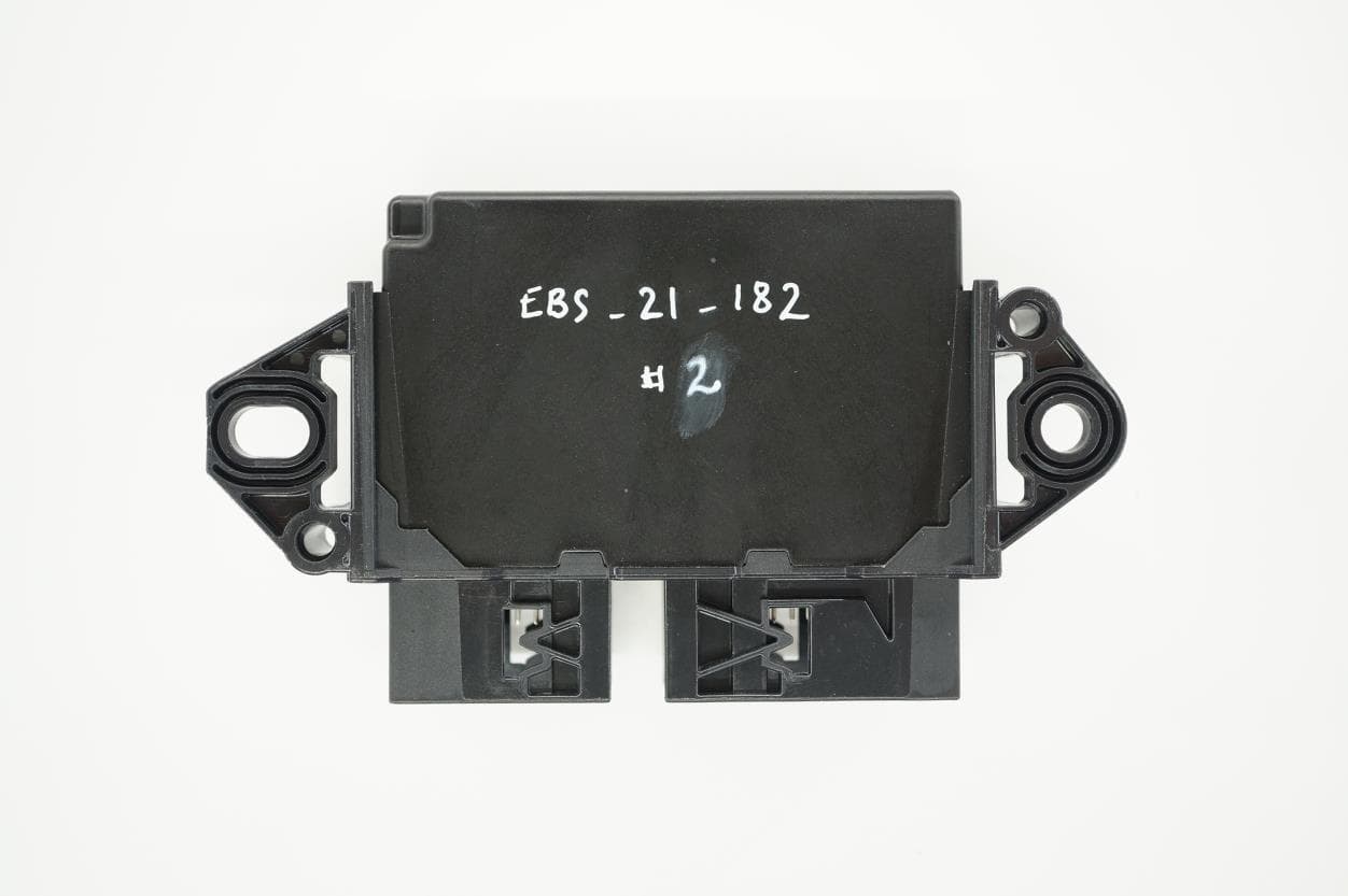
PFJPKM250
Oct 01, 2023Master ECU BT-LE+UWB
Equipment Class
DTS - Digital Transmission System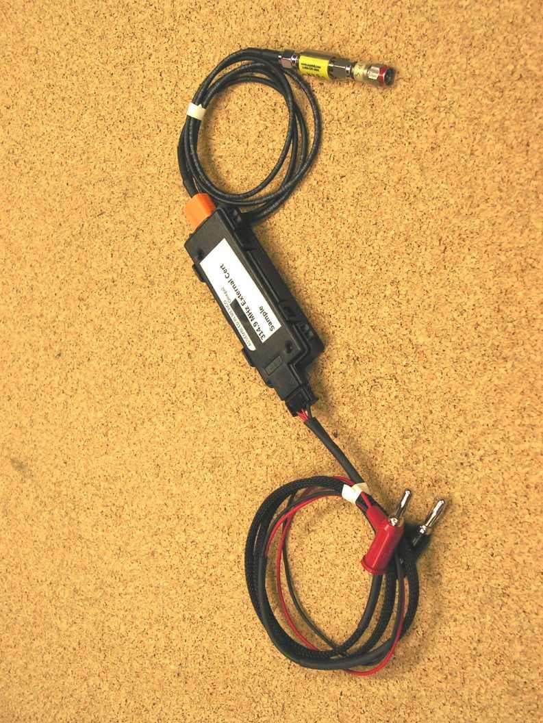
PFJG2EX23
Aug 17, 2014RF Receiver
Equipment Class
CYY - Communications Receiver used w/Pt 15 Transmitter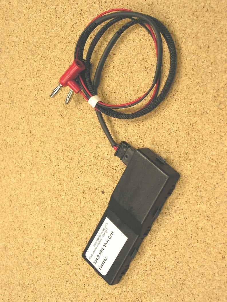
PFJG2TN23
Aug 07, 2014RF Receiver
Equipment Class
CYY - Communications Receiver used w/Pt 15 Transmitter
PFJG2TN24
Aug 07, 2014RF Receiver
Equipment Class
CYY - Communications Receiver used w/Pt 15 Transmitter
PFJG2THK4
Jul 20, 2014RF Receiver
Equipment Class
CYY - Communications Receiver used w/Pt 15 Transmitter