PFNDMT1761Digital Cable Receiver
Digital Multimedia Technology Co., Ltd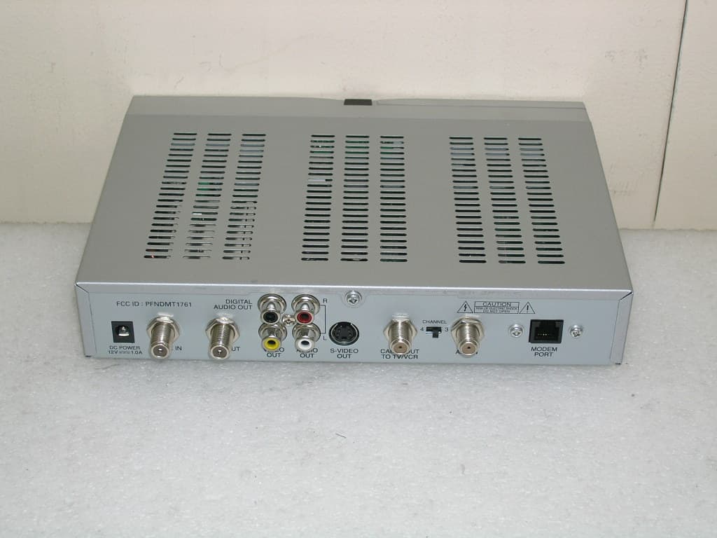
Click to zoom
Application Details
- Equipment Class
- HID - Part 15 TV Interface Device
- Date of Grant
- Feb 02, 2006
- Application Purpose
- Original Equipment
- Date of Application
- Feb 02, 2006
- Equipment Note
- Digital Cable Receiver
- Frequency Range
- 67.25000000 - 71.75000000
- Country
- South Korea
Documents & Files
Document Text
Text extracted from the exhibit documents filed with the FCC. Open a document above to read the original.
Users Manual
Front Cover LIVEWIRE OS DIGITAL SET-TOP BOX USER MANUAL Back Cover CONTACT INFO • <Mailing Address > • <Phone Number> • <Customer Service Phone Number and Address (If Different)> • <Parent Company Affiliations (If Necessary)> Important safety instructions & FCC information Safety The exclamation point within an equilateral triangle is intended to alert the user to the presence of important operating and maintenance (servicing) instructions in the literature accompanying the appliance. The lighting flash with arrowhead symbol, Within an equilateral triangle, is intended to alert the user to the presence of un-insulated “dangerous voltage” within the product’s enclosure that may be of sufficient magnitude to constitute a risk of electric shock to persons. CAUTION :TO REDUCE THE RISK OF ELECTRIC SHOK DO NOT REMOVE COVER(OR BACK) NO USER-SERVICEABLE PARTS INSIDE. REFER SERVICING TO QUALIFIED SERVICE PERSONNEL. FOR YOUR SAFETY - The space around the receiver should be clear to allow for proper ventilation of the receiver. - Do not cover the receiver or place it on a unit that emits heat - Use a damp soft cloth to clean the casing. - Do not connect or disconnect cables when the receiver is plugged in. - Do not remove the cover. - Do not allow the unit to be exposed to hot, cold or humid conditions. - Never allow liquids, spray or other materials to come into contact with the inside of the receiver. - Use only with the AC/DC Adaptor, Sunlin Electronics, Cat.No. SR689 WET LOCATION MARKING Apparatus shall not be exposed to dripping or splashing and no objects filled with liquids, such as vases, shall be placed on the apparatus. Outdoor Use Marking Warning : To prevent fire or electric shock, do not expose this appliance to rain or moisture. Cable System Installation Marking Note to CATV System Installer: This reminder is provided to call CATV system installer’s attention to Article 820-40 of the NEC that provides guidelines for proper grounding and, in particular, specifies that the cable ground shall be connected to the grounding system of the building, as close to the point of cable entry as practical Polarized Attachment plug Marking Caution : To prevent electric shock, match wide blade of plug to wide slot, fully insert. Date of Manufacture Marking Location: Bottom enclosure Important Safety Instructions 1) Read these instructions. 2) Keep these instructions. 3) Heed all warnings. 4) Follow all instructions. 5) Do not use this apparatus near water. 6) Clean only with dry cloth. 7) Do not block any ventilation openings, install in accordance with the manufacturer’s instructions. 8) Do not install near any heat sources such as radiators, heat registers, stoves, or other apparatus(including amplifiers) that produce heat. 9) Do not defeat the safety purpose of the polarized or grounding-type plug. A polarized plug has two blades with one wider than the other. A grounding type plug has two blades and a third grounding prong. The wide blade or the third prong are provided for your safety. If the provided plug does not fit into your outlet, consult an electrician for replacement of the obsolete outlet. 10) Protect the power cord from being walked on or pinched particularly at plugs, convenience receptacles, and the point where they exit from the apparatus. 11) Only use attachments/accessories specified by the manufacturer. 12) Use only with the cart, stand, tripod, bracket, or table specified by the manufacturer, or sold with the apparatus, when a cart is used, use caution when moving the cart/apparatus combination to avoid injury from tip-over. 13) Unplug this apparatus during lighting storms or when unused for long periods of time. 14) Refer all servicing to qualified service personnel. Servicing is required when the apparatus has been damaged in any, such as power-supply cord or plug is damaged. Liquid has been spilled or objects have fallen into the apparatus, the apparatus has been exposed to rain or moisture, does not operate normally, or has been dropped. FCC INFORMATION FCC ID : PFNDMT1761 This device complies with part 15 of the FCC Rules. Operation is subject to the following two conditions: 1 This device may not cause harmful interference. 2) This device must accept any interference received, including interference that may cause undesired operation. Note: This equipment has been tested and found to comply with the limits for a Class B digital device, pursuant to part 15 of the FCC Rules. These limits are designed to provide reasonable protection against harmful interference in a residential installation. This equipment generates, uses and can radiate radio frequency energy and, if not installed and used in accordance with the instructions, may cause harmful interference to radio communications. However, there is no guarantee that interference will not occur in a particular installation. If this equipment does cause harmful interference to radio or television reception, which can be determined by turning the equipment off and on, the user is encouraged to try to correct the interference by one or more of the following measures: 1 Reorient or relocate the receiving antenna. 2) Increase the separation between the equipment and Digital Set-Top Box. 3) Connect the equipment into an outlet on a circuit different from that to which the Digital Set-Top Box is connected. 4) Consult the dealer or an experienced radio/TV technician for help. Modifications not expressly approved by the manufacturer could void the user’s authority to operate the equipment under FCC rules. MODEM Instructions CAUTION - To reduce the risk of fire, use only No. 26 AWG or larger telecommunication line cord. Note : 1. Both side shell peeled 6~7mm 2. To take up positions when insert the RJ11 6P2C 3. cable wording (E216131 AWM 20251 26AWG VW-160°C 150V ETERNAL WELL) TABLE OF CONTENTS 1 YOUR DIGITAL SET-TOP BOX 1.1 Set-Top Box Details ............................................ 4 1.2 Getting Started .........................…
Text truncated - open the document above for the full version.
Block Diagram
CPU (STi5518) CPU (STi5518FQC) AUDIO DAC (CS4344) AUDIO DAC (CS4344) FLASH Memory (16Mbit) FLASH Memory (32Mbit) SDRAM (64Mbit) SDRAM (64Mbit) Television TUNER AGC & PLL LINK IC QAM FEC RCA VideoRCA RS-232 PORT RS-232 Conn. AUDIO DMT1761 Block Diagram RCA CONN. RCA CONN. VIDEO DIGITAL AUDIO Audio D/A Convertor Audio D/A Converter Audio L RCA Adaptor +12V 1A IR Receiver LED Display Key Switch IR Receiver LED Display Key Switch Conditional Access System Conditional Access System I ² C MPEG DATA RF RF Modulator Audio R RCA Conditional Access System 2.4Kbps Serial MODEM 3V3 3V3 30V5V7V3V3 30V12V7V3V32V5 5V 5V3V3 3V3 5V 5V 27 MHz 28.224 MHz
External Photos
Appendix C. External Photographs Report no. ETLE051219.016, Page 1 of 2 Head Office : # 371-51 Kasan-Dong, Keumcheon-ku, Seoul, 153-803, Korea Tel : 82-2-858-0786 Fax : 82-2-858-0788 EMC Lab : #584 Sangwhal-ri, Kanam-myon, Yoju-kun, Kyounggi-do, 469-885, Korea Tel:82-31-885-0072, Fax:82-31-885-0074 ETLQP-21-F22-0 Front side View of The EUT Rear side View of The EUT Appendix C. External Photographs Report no. ETLE051219.016, Page 2 of 2 Head Office : # 371-51 Kasan-Dong, Keumcheon-ku, Seoul, 153-803, Korea Tel : 82-2-858-0786 Fax : 82-2-858-0788 EMC Lab : #584 Sangwhal-ri, Kanam-myon, Yoju-kun, Kyounggi-do, 469-885, Korea Tel:82-31-885-0072, Fax:82-31-885-0074 ETLQP-21-F22-0 View of The Remote Control Unit
ID Label/Location Info
Appendix A. FCC ID Label and Location Report no. ETLE051229.047, Page 1 of 2 Head Office : # 371-51 Kasan-Dong, Keumcheon-ku, Seoul, 153-803, Korea Tel : 82-2-858-0786 Fax : 82-2-858-0788 EMC Lab : #584 Sangwhal-ri, Kanam-myon, Yoju-kun, Kyounggi-do, 469-885, Korea Tel:82-31-885-0072, Fax:82-31-885-0074 ETLQP-21-F22-0 Product Label Sample with FCC Label information Following is a sample copy of the label that will be placed on the rear cabinet of the product. The FCC ID Label and compliance statement are marked in the product label. Digital Multimedia Technology Co., Ltd. Digital Cable Receiver FCC ID : PFNDMT1761 Model No : DMT1761 POWER : AC/DC Adaptor: Input AC 100-240 V; 50/60 Hz; 0.5 A Output DC 12 V; 0.5 A Serial No : N/A This device complies with part 15 of the FCC Rules. Operation is subject to the following two conditions: (1) This device may not cause harmful interference, and (2) This device must accept any interference received, including interference that may cause undesired operation Manufacturer : Digital Multimedia Technology Co., Ltd. Made in Korea Appendix A. FCC ID Label and Location Report no. ETLE051229.047, Page 2 of 2 Head Office : # 371-51 Kasan-Dong, Keumcheon-ku, Seoul, 153-803, Korea Tel : 82-2-858-0786 Fax : 82-2-858-0788 EMC Lab : #584 Sangwhal-ri, Kanam-myon, Yoju-kun, Kyounggi-do, 469-885, Korea Tel:82-31-885-0072, Fax:82-31-885-0074 ETLQP-21-F22-0 Label Location The label shown shall be permanently affixed at a conspicuous location on the device and be readily visible to the user at the time purchase.(Labeling requirements per 2.925) Label here
Internal Photos
Appendix D. Internal Photographs Report no. ETLE051229.047, Page 1 of 10 Head Office : # 371-51 Kasan-Dong, Keumcheon-ku, Seoul, 153-803, Korea Tel : 82-2-858-0786 Fax : 82-2-858-0788 EMC Lab : #584 Sangwhal-ri, Kanam-myon, Yoju-kun, Kyounggi-do, 469-885, Korea Tel:82-31-885-0072, Fax:82-31-885-0074 ETLQP-21-F22-0 Inside View of The EUT Appendix D. Internal Photographs Report no. ETLE051229.047, Page 2 of 10 Head Office : # 371-51 Kasan-Dong, Keumcheon-ku, Seoul, 153-803, Korea Tel : 82-2-858-0786 Fax : 82-2-858-0788 EMC Lab : #584 Sangwhal-ri, Kanam-myon, Yoju-kun, Kyounggi-do, 469-885, Korea Tel:82-31-885-0072, Fax:82-31-885-0074 ETLQP-21-F22-0 Component side view of Main board Appendix D. Internal Photographs Report no. ETLE051229.047, Page 3 of 10 Head Office : # 371-51 Kasan-Dong, Keumcheon-ku, Seoul, 153-803, Korea Tel : 82-2-858-0786 Fax : 82-2-858-0788 EMC Lab : #584 Sangwhal-ri, Kanam-myon, Yoju-kun, Kyounggi-do, 469-885, Korea Tel:82-31-885-0072, Fax:82-31-885-0074 ETLQP-21-F22-0 Solder side view of Main board Appendix D. Internal Photographs Report no. ETLE051229.047, Page 4 of 10 Head Office : # 371-51 Kasan-Dong, Keumcheon-ku, Seoul, 153-803, Korea Tel : 82-2-858-0786 Fax : 82-2-858-0788 EMC Lab : #584 Sangwhal-ri, Kanam-myon, Yoju-kun, Kyounggi-do, 469-885, Korea Tel:82-31-885-0072, Fax:82-31-885-0074 ETLQP-21-F22-0 Inside View of The CABLE TUNER Appendix D. Internal Photographs Report no. ETLE051229.047, Page 5 of 10 Head Office : # 371-51 Kasan-Dong, Keumcheon-ku, Seoul, 153-803, Korea Tel : 82-2-858-0786 Fax : 82-2-858-0788 EMC Lab : #584 Sangwhal-ri, Kanam-myon, Yoju-kun, Kyounggi-do, 469-885, Korea Tel:82-31-885-0072, Fax:82-31-885-0074 ETLQP-21-F22-0 Component side view of Modem board Appendix D. Internal Photographs Report no. ETLE051229.047, Page 6 of 10 Head Office : # 371-51 Kasan-Dong, Keumcheon-ku, Seoul, 153-803, Korea Tel : 82-2-858-0786 Fax : 82-2-858-0788 EMC Lab : #584 Sangwhal-ri, Kanam-myon, Yoju-kun, Kyounggi-do, 469-885, Korea Tel:82-31-885-0072, Fax:82-31-885-0074 ETLQP-21-F22-0 Solder side view of Modem board Appendix D. Internal Photographs Report no. ETLE051229.047, Page 7 of 10 Head Office : # 371-51 Kasan-Dong, Keumcheon-ku, Seoul, 153-803, Korea Tel : 82-2-858-0786 Fax : 82-2-858-0788 EMC Lab : #584 Sangwhal-ri, Kanam-myon, Yoju-kun, Kyounggi-do, 469-885, Korea Tel:82-31-885-0072, Fax:82-31-885-0074 ETLQP-21-F22-0 Component side view of Front Board Solder side view of Front Board Appendix D. Internal Photographs Report no. ETLE051229.047, Page 8 of 10 Head Office : # 371-51 Kasan-Dong, Keumcheon-ku, Seoul, 153-803, Korea Tel : 82-2-858-0786 Fax : 82-2-858-0788 EMC Lab : #584 Sangwhal-ri, Kanam-myon, Yoju-kun, Kyounggi-do, 469-885, Korea Tel:82-31-885-0072, Fax:82-31-885-0074 ETLQP-21-F22-0 Inside View of The EUT of RF Modulator Appendix D. Internal Photographs Report no. ETLE051229.047, Page 9 of 10 Head Office : # 371-51 Kasan-Dong, Keumcheon-ku, Seoul, 153-803, Korea Tel : 82-2-858-0786 Fax : 82-2-858-0788 EMC Lab : #584 Sangwhal-ri, Kanam-myon, Yoju-kun, Kyounggi-do, 469-885, Korea Tel:82-31-885-0072, Fax:82-31-885-0074 ETLQP-21-F22-0 Component side view RF Modulator View of Front Cover Appendix D. Internal Photographs Report no. ETLE051229.047, Page 10 of 10 Head Office : # 371-51 Kasan-Dong, Keumcheon-ku, Seoul, 153-803, Korea Tel : 82-2-858-0786 Fax : 82-2-858-0788 EMC Lab : #584 Sangwhal-ri, Kanam-myon, Yoju-kun, Kyounggi-do, 469-885, Korea Tel:82-31-885-0072, Fax:82-31-885-0074 ETLQP-21-F22-0 View of Bottom cover View of Top cover
Operational Description
1 I. Operation Description 1. STI 5518 Related 2. Front-End Interface 3. A/V Interface 4. Modem Interface 6. Power Supply Interface 1. STI5518 Related (1) Configuration STI5518 is 1 chip for DVB, DSS Set Top Box including 32bit host CPU, A/V Demux, Video Encoder, Multi PIO, Cache RAM etc.... Summarized features by Block parts are as follows; Function improvment by using 32bit host CPU Core of maximum 81MHZ Clock. Uses inner buffer of 4KB SRAM, 2KB ICACHE, 2KB DCACHE. Built-in Video Decoder Supporting MPEG-2 MP@ML , Letter box Picture 1. Sti5518 Block Diagram Video. Built-in MPEG Layer1, 2 Audio Decoder. IEC60958 digital output having AC3 by-pass function. Supports 2 - 8bit/pixel OSD. Built-in Video Encoder for RGB, CVBS, Y/C Video Output. CPU & Decoder performance improvement by supporting maximum 64Mbit SDRAM. Variable outer interface memory support ( 4 Banks ). H/W DMUX, Serial parallel Input, 32Pid Support. 8 Level INT Support. DMA & Multi PID Support. (2) Reset Every Register Values are initialized when Low Signal is approved in Reset Pin of Sti5518. Reset Pin should be high after carrying out the follow conditions; z After stablizing of Clock and POWER z After not RSTPin becomes Low When Reset Pin becomes High, CPU accomplishes booting procedure. (3) Clock Clock uses 27MHz and is made in VCXO. Control Voltage of VCXO fits a Synchronous Machine of exact MPEG by using PWM of sti5518 revising and referring to PCR Value of MPEG. If this value is abnormal, Video could have no color or, Screen could be broken. Sti5518 uses making every operation clock used inside using a outer 27MHz clock. (4) PIO Configuration PIO supported in Sti5518 supports 6 ports which are PIO0, PIO1, PIO2, PIO3, PIO4, PIO5. Some ports are used in compounding with S/W adding special function in general PIO function for extension. (5) Memory Interface Sti5518 supports 2KB Data Cache, 4KB SRAM or Data Cache, 2KB Instruction Cache, which is On-chip Memory, and ROM, DRAM, which is Outer Extension Memory. Also, Using SDRAM can be used up to 64Mbits as MPEG Memory, Now by using Code on SDRAM formula, 32Mbits of 64Mbits SDRAM is used as MPEG Buffer, and the rest 32Mbits is used as Code Buffer. 2. Front-End Interface (1) Tuner Module This Cable NIM(Network Interface Module)is designed for using in DBV-C system. It builts in QAM-Demod IC. It covers a center frequency range from 50 ~ 870MHz. It’s used to a single conversion approach with the reception frequency range in VHF low, VHF high and UHF. 3. A/V Interface (1) Video Digital Encoder of PAL/NTSC is built in Sti5518. Digital Encoder converts Digital Video Stream, OSD, Sub-picture of 4:2:2 or 4:4:4, and makes Analogue Base band PAL/NTSC Signal Encoder Output supports Interlace mode or Non-interlace mode. There is 3 Analogue Video Output Pin. (CVBS, S-VHS(Y/C)). Also, supports Teletext, closed-captions, CGMS. 1) Video Output DMT1761 has 2 Video Output Port(RCA JACK, RF_MODULATOR). Y,C Signal is output from S-VHS JACK through Video Buffer & LPF(Low Pass Filter) on STI5518 Output. CVBS Signal is output from LPF on STI5518 Output. (2) Audio Audio related Output of Sti5518 is possible as PCM Type and AC3 Interface Type. DMT1761 uses Serial Data of PCM Format & Digital Audio output of SPDIF Format. PCM Data Output Format is possible as Standard & I2S Compatible PCM Format. Interface Signal of PCM Format is as follows; z PCMDATA (Sti5518 Pin52) : PCM Serial Data Output z SCLK (Sti5518 Pin51) : PCM Clock Output z LRCLK (Sti5518 Pin56) : Left/Right Channel select z PCMCLK (Sti5518 Pin55) : PCM Clock Input(18.432Mhz) Data of PCM Format is output from outer Output Port converting as Analogue Signal in outer Audio DAC through Output Amplifier & AV Switch. Analogue Audio Signal converted In Audio DAC is output from STi5518 or Buffer after amplifying 3 times in amplification level through Low Pass Filter. In the meantime outputs Digital Audio Output having AC3 by-pass Function of SPDIF Format in PIN57 of STI5518. This is output as 1Vp-p from RCA JACK which is Output Terminal through Buffer Circuit. 4. Modem Interface A modem modulates outgoing digital signals from a computer or other digital device to analog signals for a conventional copper twisted pair telephone line and demodulates the incoming analog signal and converts it to a digital signal for the digital device. In recent years, the 2400 bits per second modem that could carry e-mail has become obsolete. 14.4 Kbps and 28.8 Kbps modems were temporary landing places on the way to the much higher bandwidth devices and carriers of tomorrow. From early 1998, most new personal computers came with 56 Kbps modems. By comparison, using a digital Integrated Services Digital Network adapter instead of a conventional modem, the same telephone wire can now carry up to 128 Kbps. With Digital Subscriber Line (DSL) systems, now being deployed in a number of communities, bandwidth on twisted-pair can be in the megabit range. 5. Power Supply Interface Power Supply provides every power required in STB, and Spec is as follows. Type : External Adapter (90~240V AC @ 50/60Hz , 0.3A) Main Output voltage : 12V DC / 1.0A Nominal power consumption : 10W
Test Report
This report only responds to the tested sample and may not be reproduced, except in full, without written approval of the ETL,Inc. www.etl.re.kr E-RAE Testing Laboratory Electromagnetic Emission FCC MEASUREMENT REPORT CERTIFICATION OF COMPLIANCE FCC Part 15 Certification Measurement This Digital Cable Receiver, Model DMT1761 has been tested in accordance with the measurement procedures specified in ANSI C63.4-2003 at the ETL/EMC Test Laboratory and has been shown to complied with the electromagnetic radiated emission limits specified in FCC Rule Part15 Subpart B: TV interface device. I attest to the accuracy of data. All measurement here in was performed by me or was made under my supervision and is correct to the best of my knowledge and belief. I assume full responsibility for the completeness of these measurements and vouch for the qualifications of all persons taking them. The results of testing in this report apply to the product/system, which was tested only. Other similar equipment will not necessarily produce the same results due to production tolerance and measurement uncertainties. Hyung Seok, Lee / Chief Engineer ETL Inc. #584 Sangwhal-ri, Kanam-myon, Yoju-kun, Kyounggi-do, 469-885, Korea Tel : (031) 885-0072 Fax : (031) 885-0074 PRODUCT : Digital Cable Receiver MODEL/TYPE NO : DMT1761 FCC ID : PFNDMT1761 APPLICANT / ADDRESS : Digital Multimedia Technology Co., Ltd. Doorim Bldg. 4th Fl, Poi-Dong, Kangnam-Gu, Seoul, Korea Attn.:Ka Young, Kim / Manager MANUFACTURER : Same as applicant FCC CLASSIFICATION : HID : TV interface device FCC RULE PART(S) : FCC Part 15 Subpart B FCC PROCEDURE : Certification TRADE NAME : TEST REPORT No. : ETLE051229.047 DATES OF TEST : December 29, 2005 - January 10, 2006 REPORT ISSUE DATE : January 13, 2006 TEST LABORATORY : ETL Inc. (FCC Registration Number: 95422) Report no. ETLE051229.047, Page 2 of 23 Head Office : # 371-51 Kasan-Dong, Keumcheon-ku, Seoul, 153-803, Korea Tel : 82-2-858-0786 Fax : 82-2-858-0788 EMC Lab : #584 Sangwhal-ri, Kanam-myon, Yoju-kun, Kyounggi-do, 469-885, Korea Tel:82-31-885-0072, Fax:82-31-885-0074 ETLQP-21-F22-0 FCC TEST REPORT Table of Contents ATTACHMENT A: COVER LETTER(S) FCC Measurement Report 1. Introduction 2. Product Information 3. Description of Tests 4. Test Condition 5. Test Results 5.1 Summary of Test Results 5.2 Conducted Emission Test 5.3 Radiated Emission Test 5.4 Antenna Power Conduction Meaurement 5.5 Output Signal Level Measurement 5.6 Output Terminal Conducted Spurious Emission Measurement 5.7 Transfer Switch Measurement 6. Sample Calculation 7. List of test Equipment used for Measurements Appendix A. FCC ID Label and Location Appendix B. Test Setup Photographs Appendix C. External Photographs Appendix D. Internal Photographs Appendix E. Block Diagram Appendix F. Operating Manual Report no. ETLE051229.047, Page 3 of 23 Head Office : # 371-51 Kasan-Dong, Keumcheon-ku, Seoul, 153-803, Korea Tel : 82-2-858-0786 Fax : 82-2-858-0788 EMC Lab : #584 Sangwhal-ri, Kanam-myon, Yoju-kun, Kyounggi-do, 469-885, Korea Tel:82-31-885-0072, Fax:82-31-885-0074 ETLQP-21-F22-0 FCC TEST REPORT FCC MEASUREMENT REPORT Scope – Measurement and determination of electromagnetic emission(EME) of radio frequency devices including intentional radiators and/or unintentional radiators for compliance with the technical rules and regulations of the U.S Federal Communications Commission(FCC) General Information z EUT Type : Digital Cable Receiver z Model Number : DMT1761 z FCC Identifier : PFNDMT1761 z S/N : N/A z Freq. Range : 61.25 MHz – 71.75 MHz z FCC Rule Part(s) : Part 15 Subpart B z Test Procedure : ANSI C63.4-2003 z FCC Classification : TV Interface Device z RF Channels : Ch. 3 / Ch. 4 z Dates of Tests : December 29, 2005 - January 10, 2006 z Place of Tests : ETL Inc. 584, Sangwhal-Ri, Kanam-Myun, Yoju-Kun, Kyounggi-Do, Korea Tel : 82-31- 885-0072 Fax : 82-31- 885-0074 z Test Report No. : ETLE051229.047 Applicant Name : Digital Multimedia Technology Co., Ltd. Address : Doorim Bldg. 4th Fl, Poi-Dong, Kangnam-Gu, Seoul, Korea Attention : Attn.:Ka Young, Kim / Manager Report no. ETLE051229.047, Page 4 of 23 Head Office : # 371-51 Kasan-Dong, Keumcheon-ku, Seoul, 153-803, Korea Tel : 82-2-858-0786 Fax : 82-2-858-0788 EMC Lab : #584 Sangwhal-ri, Kanam-myon, Yoju-kun, Kyounggi-do, 469-885, Korea Tel:82-31-885-0072, Fax:82-31-885-0074 ETLQP-21-F22-0 FCC TEST REPORT 1. INTRODUCTION The measurement test for radiated and conducted emission test were conducted at the shielded anechoic chamber room and open area test site of E-RAE Testing Laboratory Inc. facility located at 584, Sangwhal-ri, Ganam-myun, Youju-kun, Kyoungki-do, Korea. The site is constructed in conformance with the requirements of the ANSI C63.4-2003 and CISPR Publication 16. The ETL has site descriptions on file with the FCC for 3 and 10 meter site configurations. Detailed description of test facility was found to be in compliance with the requirements of Section 2.948 FCC Rules according to the ANSI C63.4-2003 and registered to the Federal Communications Commission(Registration Number : 95422 ). The measurement procedure described in American National Standard for Method of Measurement of Radio- Noise Emission from Low-Voltage Electrical and Electronic Equipment in the Range of 9 kHz to 40 GHz (ANSI C63.4-2003) was used in determining radiated and conducted emissions from the Digital Multimedia Technology Co., Ltd./ Digital Cable Receiver / Model : DMT1761 Report no. ETLE051229.047, Page 5 of 23 Head Office : # 371-51 Kasan-Dong, Keumcheon-ku, Seoul, 153-803, Korea Tel : 82-2-858-0786 Fax : 82-2-858-0788 EMC Lab : #584 Sangwhal-ri, Kanam-myon, Yoju-kun, Kyounggi-do, 469-885, Korea Tel:82-31-885-0072, Fax:82-31-885-0074 ETLQP-21-F22-0 FCC TEST REPORT 2. PRODUCT INFORMATION 2.1 Equipment Description The Equipment Under Test(EUT) is the Digital Multimedia Technology Co., Ltd.. / Digital Cable Receiver / Model : DMT1761 2.2 General Specification - Chassis Type : Metal - List of…
Text truncated - open the document above for the full version.
Test Setup Photos
Appendix B. Test Setup Photographs Report no. ETLE051229.047, Page 1 of 4 Head Office : # 371-51 Kasan-Dong, Keumcheon-ku, Seoul, 153-803, Korea Tel : 82-2-858-0786 Fax : 82-2-858-0788 EMC Lab : #584 Sangwhal-ri, Kanam-myon, Yoju-kun, Kyounggi-do, 469-885, Korea Tel:82-31-885-0072, Fax:82-31-885-0074 ETLQP-21-F22-0 Radiated Emission Test Setup Appendix B. Test Setup Photographs Report no. ETLE051229.047, Page 2 of 4 Head Office : # 371-51 Kasan-Dong, Keumcheon-ku, Seoul, 153-803, Korea Tel : 82-2-858-0786 Fax : 82-2-858-0788 EMC Lab : #584 Sangwhal-ri, Kanam-myon, Yoju-kun, Kyounggi-do, 469-885, Korea Tel:82-31-885-0072, Fax:82-31-885-0074 ETLQP-21-F22-0 Conducted Emission Test Setup Appendix B. Test Setup Photographs Report no. ETLE051229.047, Page 3 of 4 Head Office : # 371-51 Kasan-Dong, Keumcheon-ku, Seoul, 153-803, Korea Tel : 82-2-858-0786 Fax : 82-2-858-0788 EMC Lab : #584 Sangwhal-ri, Kanam-myon, Yoju-kun, Kyounggi-do, 469-885, Korea Tel:82-31-885-0072, Fax:82-31-885-0074 ETLQP-21-F22-0 Antenna Power Conduction Measurement Test Setup Output Signal Level Measurement Test Setup Appendix B. Test Setup Photographs Report no. ETLE051229.047, Page 4 of 4 Head Office : # 371-51 Kasan-Dong, Keumcheon-ku, Seoul, 153-803, Korea Tel : 82-2-858-0786 Fax : 82-2-858-0788 EMC Lab : #584 Sangwhal-ri, Kanam-myon, Yoju-kun, Kyounggi-do, 469-885, Korea Tel:82-31-885-0072, Fax:82-31-885-0074 ETLQP-21-F22-0 Output Terminal Conducted Spurious Emission Measurement Test Setup Antenna Transfer Switch Measurement
Contact Information
Applicant
Jung Hwan Lee(Senior Research Engineer)
Test Firm
E-RAE Testing LaboratoryYo Han Park
Technical Specifications
| # | Rule Parts | Frequency Range | Power Output |
|---|---|---|---|
| 2 | 15B | 67.25 MHz - 71.75 MHz | - |
Other Applications from Digital Multimedia Technology Co., Ltd
PFNIPH3004HDM
Dec 21, 2015Set top box
Equipment Class
DTS - Digital Transmission System
PFNDMS2444UHDW
Jul 08, 2015Set-top Box
Equipment Class
HID - Part 15 TV Interface Device
PFNDMS2444UHDS
May 27, 2015SET-TOP BOX
Equipment Class
HID - Part 15 TV Interface Device
PFNDMS2004UHD
May 26, 2015SET-TOP BOX
Equipment Class
HID - Part 15 TV Interface Device
PFNDMS-2344UHDS
Apr 27, 2014HD Set-Top Box
Equipment Class
HID - Part 15 TV Interface Device