PFNDMT6000CXCIDigital Satellite Receiver
Digital Multimedia Technology Co., Ltd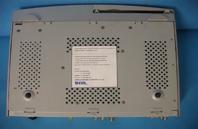
Click to zoom
Application Details
- Equipment Class
- HID - Part 15 TV Interface Device
- Date of Grant
- Jul 29, 2002
- Application Purpose
- Original Equipment
- Date of Application
- Jul 29, 2002
- Equipment Note
- Digital Satellite Receiver
- Frequency Range
- 950.00000000 - 960.00000000
- Country
- South Korea
Documents & Files
Document Text
Text extracted from the exhibit documents filed with the FCC. Open a document above to read the original.
Users Manual
DMT6000 CXCI DMT6000 CXCI User’s Guide Channel Manager Channel Manager Favorite Channel Move Channel Lock Channel Rename Channel Delete Channel Sort Channel Fast Edit mode Go to Function Electronic Program Guide (EPG) Timer Antenna Direction Help Front Panel Display Trouble Shooting System Specification 34 34 35 35 36 36 37 37 38 38 39 40 41 DSR -Digital Satellite Receiver CONTENTS Page Page 19 21 21 22 23 26 27 28 29 30 General Function Select Channel Pause the Screen Previous Channel Recall TV & Radio Mode TV & VCR Mode Channel Information Volume & Audio Control 31 31 32 32 32 32 33 33 Safety For your safety Outdoor Use Marking Cable System Installation Marking Polarized Attachment plug Marking Important Safety Instruction FCC Information General Information Main Features For Your Safety Unpacking General Operation Remote Control Unit (RCU) Front Panel Rear Panel Installation Connecting to Antenna & TV Connecting to TV & VCR using SCART Connecting to TV using RCA support Connecting to TV using RF support Connecting to another Receiver Menu Information User Installation Antenna Setup -1)DiSEqC1.2 Antenna Setup -2) Fixed Channel Search -1)DiSEqC1.2 Channel Search -2) Fixed System Setting Parental Lock Factory Default Common Interface 10 10 11 12 12 13 14 15 16 16 16 17 17 18 42 43 45 3 4 4 4 4 5 9 -3- COUTION :TO REDUCE THE RISK OF ELECTRIC SHOK DO NOT REMOVE COVER(OR BACK) NO USER-SERVICEABLE PARTS INSIDE. REFER SERVICING TO QUALIFIED SERVICE PERSONNEL. The lighting flash with arrowhead symbol, Within an equilateral triangle, is intended to alert the user to the presence of uninsulated “dangerous voltage”within the product’s enclosure that may be of sufficient magnitude to constitute a risk of electric shock to persons. The exclamation point within an equilateral triangle is intended to alert the user to the presence of important operating and maintenance (servicing) instructions in the literature accompanying the appliance. Safety -4- For Your Safety •The space around the receiver should be clear to allow for proper ventilation of the receiver. •Do not cover the Receiver or place it on a unit that emits heat •Use a damp soft cloth to clean the casing. •Do not remove the cover •Do not allow the unit to be exposed to hot, cold or humid conditions •Never allow liquids, spray or other materials to come into contact with the inside of the Receiver. •Do not connect or disconnect cables when the Receiver is plugged in. Outdoor Use Marking Warning : To prevent fire of electric shock, do not expose this appliance to rain or moisture. Cable System Installation Marking Note to CATV System Installer : This reminder is provided to call CATV system installer’s attention to Article 820-40 of the NEC that provides guidelines for proper grounding and,in particular, specifies that the cable ground shall be connected to the grounding system of the building, as close to the point of cable entry as practical Polarized Attachment plug Marking Caution : To prevent electric shock, match wide blade of plug towide slot, fully insert. Safety Important Safety Instruction -5- 1) Read Instructions:All the safety and operating instructions should be read before the product is operated. 2) Retain Instructions:The safety and operating instruction should be retained for future reference. 3) Head Warnings:All warnings on the product and in the operating instructions should be adhered to. 4) Follow instructions:All operating and use instructions should be followed. 5) Cleaning:Unplug this product from the wall outlet before cleaning. Do not use liquid cleaners or aerosol cleaner. Use a damp cloth for cleaning. 6) Exception:A product that is meant or uninterrupted service and that for some specific reason, such as the possibility of the loss of and authorization code for c CATV converter, is not intended to be unplugged by the user for cleaning or any other purpose, may exclude the reference to unplugging the product in the cleaning description otherwise required in this article. 7) Attachment:Do not use attachments not recommended by the product manufacturer as they may cause hazards. 8) Water and Moisture: Do not use the product near water for example, near a bath, wash bowl, kitchen sink, or laundry tub ; in a wet basement; or r,ear a swimming pool; and the like. 9) Accessories: Do not place this product on an unstable cart, stand, tripod, bracket, or table. This product may fall, causing serious injuryto a child or adult, and serious damage to the product. Use 10) A product and cart combination should be moved with care. Quick stops, excessive force, and uneven surface may cause the product and cart combination tooverturn. Please refer to picture 1 in the end of this chapter. 11) Ventilation–Slot and openings in the cabinet are provided for ventilation and to ensure reliable operation of the product and to protest it from overheating, and these openings must not be blocked by covered. The openings should never be blocked by placing the product on a bed, sofa, rug, or other similar surface. This product should not be placed in a built-in installation such as a bookcase or rack unless proper ventilation is provided or the manufacturer’s instructions have been adhered to. 12) Power sources: This product should be operated only from the type of power source indicated on the marking label. If you are not sure of the type of power supply to your home, consult your product dealer or local power company. For products intended to operate from battery power, or other sources, refer to the operating instructions. Safety -6- Important Safety Instruction 13) Grounding or Polarization: This product may be equipped with a polarized alternating- current line plug(a plug having on blade wider than the other). This plug will fit into the power outlet only on way. This is a safety feature. If you are unable to insert the plug gully into the outlet, try reversing the plug. If the plug should still fail to fir, contact your electrician to…
Text truncated - open the document above for the full version.
Block Diagram
CPU (STi5518) Operate Freq.80MHz CPU (STi5518) Operate Freq.80MHz AUDIO D/A(UDA1320) AUDIO D/A(UDA1320) FLASH ROM (8Mbit) FLASH ROM (8Mbit) SDRAM (64Mbit) (120MHz) SDRAM (64Mbit) (120MHz) Television Satellite dish TUNER Input Freq. 950~2150MHz AGC & PLL LINK IC QPSK FEC I 2 C BUS RCA CON RCA CON PC CARD C. A. MODULE PC CARD C. A. MODULE CIMAX (Buffer) CIMAX (Buffer) RF MOD RF MOD S-VHS (Otion) S-VHS (Otion) RS-232 PORT RS-232 PORT AV S/W (MM1232) AV S/W (MM1232) AUDIO IR Receiver (38.1KHz) & Switch IR Receiver (38.1KHz) & Switch DMT6000 CXCI Block Diagram SMPS +5V +3.3V +12V +30V +21V +7V RCACON (Otion) RCACON (Otion) VIDEO DIGITAL AUDIO SMART CARD SMART CARD Audio D/AConvertor Audio D/A Convertor
External Photos
IST Co., Ltd . EMC LABORATORY External Photos.Ref.No : 02-IST-143 1 of 3 The DUT photos Front View Rear View IST Co., Ltd . EMC LABORATORY External Photos.Ref.No : 02-IST-143 2 of 3 The DUT photos Side View Side View IST Co., Ltd . EMC LABORATORY External Photos.Ref.No : 02-IST-143 3 of 3 The DUT photos Bottom View
ID Label/Location Info
IST Co., Ltd . EMC LABORATORY Label Location.Ref.No : 02-IST-143 1 of 1 Label Sample Label Location Label Location
Internal Photos
IST Co., Ltd. EMC LABORATORY Internal Photos. Ref.No: 02-IST-143 1 of 10 The DUT photos Inner Top View Inner Top View IST Co., Ltd. EMC LABORATORY Internal Photos. Ref.No: 02-IST-143 2 of 10 The DUT photos Main Board PCB Parts View Main Board PCB Copper View IST Co., Ltd. EMC LABORATORY Internal Photos. Ref.No: 02-IST-143 3 of 10 The DUT photos SUB Board PCB Parts View SUB Board PCB Copper View IST Co., Ltd. EMC LABORATORY Internal Photos. Ref.No: 02-IST-143 4 of 10 The DUT photos Power Board PCB Parts View Power Board PCB Copper View IST Co., Ltd. EMC LABORATORY Internal Photos. Ref.No: 02-IST-143 5 of 10 The DUT photos Control Panel PCB Parts View Control Panel PCB Copper View IST Co., Ltd. EMC LABORATORY Internal Photos. Ref.No: 02-IST-143 6 of 10 The DUT photos Top Cover/Inner Front Inner Bottom IST Co., Ltd. EMC LABORATORY Internal Photos. Ref.No: 02-IST-143 7 of 10 Tuner photos(SHARP: BS2F7VZ0184) Front View Rear View IST Co., Ltd. EMC LABORATORY Internal Photos. Ref.No: 02-IST-143 8 of 10 Tuner photos(SHARP: BS2F7VZ0184) Inner View Inner View IST Co., Ltd. EMC LABORATORY Internal Photos. Ref.No: 02-IST-143 9 of 10 RF Modulator photos(LG INNOTEK:TAMC-H001F) Front View Rear View IST Co., Ltd. EMC LABORATORY Internal Photos. Ref.No: 02-IST-143 10 of 10 RF Modulator photos(LG INNOTEK:TAMC-H001F) Inner View Inner View
Test Report
IST Co., Ltd. EMC LABORATORY Test Setup Photos. Ref. No: 02-IST-143 1 of 2 Test Setup Photos – Radiated Emissions Front View Rear View IST Co., Ltd. EMC LABORATORY Test Setup Photos. Ref. No: 02-IST-143 2 of 2 Test Setup Photos – Conducted Emissions Front View Rear View
Test Setup Photos
IST Co., Ltd. EMC LABORATORY Test Setup Photos. Ref. No: 02-IST-143 1 of 2 Test Setup Photos – Radiated Emissions Front View Rear View IST Co., Ltd. EMC LABORATORY Test Setup Photos. Ref. No: 02-IST-143 2 of 2 Test Setup Photos – Conducted Emissions Front View Rear View
Contact Information
Applicant
Jung Hwan Lee(Senior Research Engineer)
Test Firm
IST Co., LtdBong Kyoon Bae
Technical Specifications
| # | Rule Parts | Frequency Range | Power Output |
|---|---|---|---|
| 2 | 15B | 950 MHz - 960 MHz | - |
Other Applications from Digital Multimedia Technology Co., Ltd
PFNIPH3004HDM
Dec 21, 2015Set top box
Equipment Class
DTS - Digital Transmission System
PFNDMS2444UHDW
Jul 08, 2015Set-top Box
Equipment Class
HID - Part 15 TV Interface Device
PFNDMS2444UHDS
May 27, 2015SET-TOP BOX
Equipment Class
HID - Part 15 TV Interface Device
PFNDMS2004UHD
May 26, 2015SET-TOP BOX
Equipment Class
HID - Part 15 TV Interface Device
PFNDMS-2344UHDS
Apr 27, 2014HD Set-Top Box
Equipment Class
HID - Part 15 TV Interface Device