PFU-12-200XWireless Pool/Spa Controller
Polaris Pool Systems, Inc.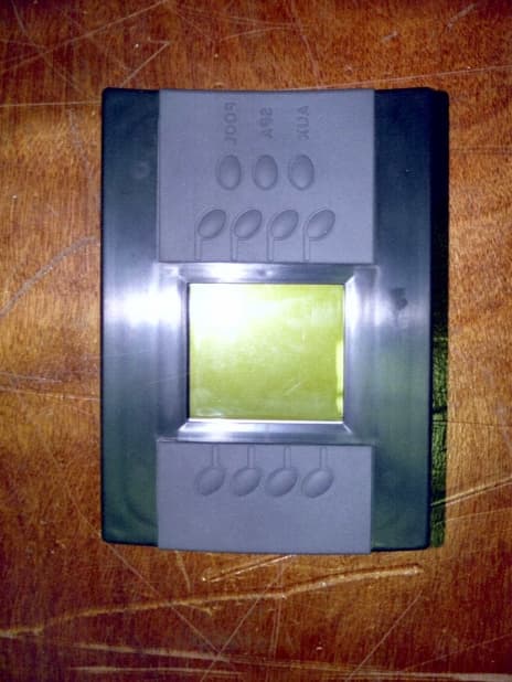
Click to zoom
Application Details
- Equipment Class
- DXT - Part 15 Low Power Transceiver, Rx Verified
- Date of Grant
- Jan 26, 2001
- Application Purpose
- Original Equipment
- Date of Application
- Jan 26, 2001
- Equipment Note
- Wireless Pool/Spa Controller
- Frequency Range
- 916.30000000 - 916.70000000
- Company
- Polaris Pool Systems, Inc.
- Country
- United States
Documents & Files
Document Text
Text extracted from the exhibit documents filed with the FCC. Open a document above to read the original.
Users Manual
OWNER’S MANUAL / INSTRUCTIONS TO THE USER INSTRUCTIONS TO THE USER This equipment has been tested and found to comply with the limits for a class B digital device, pursuant to part 15 of the FCC Rules. These limits are design to provide reasonable protection against harmful interference in a residential installation. This equipment generates, uses and can radiate radio frequency energy and if not installed and used in accordance with the instructions, may cause harmful interference to radio communications. However, there is no guarantee that interference will not occur in a particular installation. If this equipment does cause harmful interference to radio or television reception, which can be determined by turning the equipment off and on, the user is encouraged to try to correct the interference by one or more of the following measures" • Reorient or relocate the receiving antenna. • Increase the separation between the equipment and the base unit. Modifications made to the equipment without the approval of the manufacturer could void the user's authority to operate this equipment.
Attestation Statements
LETTER OF AUTHORITY / DRUG ATTESTATION
External Photos
EXTERNAL PHOTOGRAPHS FRONT VIEW OF EUT FRONT VIEW OF BATTERY CHARGER AND REMOTE CONTROL FRONT VIEW OF BATTERY CHARGER (NO REMOTE CONTROL) REAR VIEW OF BATTERY CHARGER TOP VIEW OF REMOTE CONTROL BOTTOM VIEW OF REMOTE CONTROL
ID Label/Location Info
FCC LABEL AND ITS LOCATION This label will be located on the inside of the front door on the command center. SAMPLE OF FCC LABEL (COMMAND CENTER) SAMPLE OF FCC LABEL (BATTERY CHARGER)
Internal Photos
TOP INSIDE VIEW OF BATTERY CHARGER INSIDE VIEW OF BATTERY CHARGER BOTTOM COVER TOP VIEW OF BATTERY CHARGER CIRCUIT BOARD BOTTOM VIEW OF BATTERY CHARGER CIRCUIT BOARD INSIDE VIEW OF BATTERY CHARGER WITHOUT CIRCUIT BOARD BOTTOM VIEW OF REMOTE CONTROL (BATTERY COVER OPEN) TOP INSIDE VIEW OF REMOTE CONTROL INSIDE VIEW OF REMOTE CONTROL TOP COVER TOP VIEW OF REMOTE CONTROL CIRCUIT BOARD BOTTOM VIEW OF REMOTE CONTROL CIRCUIT BOARD INSIDE VIEW OF REMOTE CONTROL BOTTOM COVER TOP VIEW OF REMOTE CONTROL CIRCUIT BOARD (LCD REMOVED) TOP VIEW OF REMOTE CONTROL LCD DISPLAY BOARD BOTTOM VIEW OF REMOTE CONTROL LCD DISPLAY BOARD
Internal Photos
FRONT VIEW OF COMMAND CENTER (DOOR OPEN) FRONT VIEW OF COMMAND CENTER (DOOR OPEN) FRONT VIEW OF COMMAND CENTER (INSIDE COVER OFF) FRONT VIEW OF COMMAND CENTER (CONTROL PANEL)
Internal Photos
FRONT VIEW OF COMMAND CENTER (RELAYS) TOP VIEW OF COMMAND CENTER CIRCUIT BOARD
Internal Photos
BOTTOM VIEW OF COMMAND CENTER CIRCUIT BOARD
Internal Photos
INSIDE VIEW OF COMMAND CENTER (TRANSFORMER/ANTENNA)
Operational Description
ELECTRO MAGNETIC TEST, INC. 1547 Plymouth Street, Mountain View, CA 94043 Tel: (650) 965-4000 Fax: (650) 965-3000 OPERATIONAL DESCRIPTION ELECTRO MAGNETIC TEST, INC. 1547 Plymouth Street, Mountain View, CA 94043 Tel: (650) 965-4000 Fax: (650) 965-3000 Polaris Sol Functional Description The Polaris Sol is an automated swimming pool/spa controller. The unit will turn on or off various pieces of equipment either at scheduled on/off times or manually through input from a wireless remote control unit or directly by accessing the main control panel of the unit located inside the sheet metal enclosure. The equipment controlled by this unit will range from standard swimming pool equipment including pumps, underwater lighting, fiber optic light sources, air blowers, heaters, and automatic valve actuators to landscape lighting, exterior lighting, and virtually any accessory operating at 120 or 240 Volts. With the exception of booster pumps used to supply water to pressure side cleaners and to air blowers, Polaris Pool Systems, Inc., is not the manufacturer of any of these accessories that can be controlled by the Sol controller. Automatic valve actuators are used to automatically divert water from one item to another. These devices are used primarily to divert pool suction and return to a spa when using a spa or to divert some water from returning to the pool in order to produce flow for a waterfall. The controller simply turns the valve actuator on and off and based on the design of the actuator, it will rotate the valve diverter in one direction or the other depending on whether it is “on” or “off”. The controller will turn on or off any of the equipment at times the user pre-sets as any digital timer would. For items such as pumps, lights, or air blowers, the signal to turn on simply closes a set of contacts on a relay and the high voltage equipment is turned on. When the signal from the controller tells the equipment to turn off, the contact on the relay is opened up and the equipment is turned off. The heater is controlled by reading a temperature from a sensor located in the water stream and turning the heater on or off based on that temperature reading. None of the safety devices built into the heater are over-ridden or removed during the installation of our controller. The thermostat on the controller simply replaces the thermostat on the heater and the controller then tells the heater when to turn on or off.
Test Report
FCC Class B Report Number: M01201A1 Page 2 of 15 ELECTRO MAGNETIC TEST, INC. 1547 Plymouth Street, Mountain View, CA 94043 Tel: (650) 965-4000 Fax: (650) 965-3000 TABLE OF CONTENTS SECTIONTITLEPAGE GENERAL REPORT SUMMARY04 SUMMARY OF TEST RESULTS04 1.PURPOSE05 2.ADMINISTRATIVE DATA06 2.1Location of Testin g06 2.2Traceabilit y Statement06 2.3Cognizant Personnel06 2.4Date Test Sample was Received06 2.5Dis position of the Test Sample06 2.6Abbreviations and Acronyms06 3.APPLICABLE DOCUMENTS07 4.DESCRIPTION OF TEST CONFIGURATIONS08 4.1Descri ption of Test Configuration - EMI08 4.1.1Cable Construction and Termination09 5.LIST OF EUT , ACCESSORIES AND TEST EQUIPMENT10 5.1EUT and Accessory List10 5.2EMI Test E quipment11 6.TEST SITE DESCRIPTION12 6.1Test Facilit y Description12 6.2EUT Mountin g, Bonding and Grounding12 7.TEST PROCEDURES13 7.1RF Emissions13 7.1.1Conducted Emissions Test13 7.1.2Radiated Emissions Test14 8.0CONCLUSIONS15 FCC Class B Report Number: M01201A1 Page 3 of 15 ELECTRO MAGNETIC TEST, INC. 1547 Plymouth Street, Mountain View, CA 94043 Tel: (650) 965-4000 Fax: (650) 965-3000 LIST OF APPENDICES APPENDIXTITLE A Radiated and Conducted Emissions Data Sheets Plot of Bandwidth of Fundamental Frequency B Test Setup Diagrams C Antenna and Effective Gain Factors LIST OF FIGURES FIGURETITLE 1 Conducted Emissions Test Setup 2 Plot Map And Layout of Test Site 3 Equipment Configuration Block Diagram FCC Class B Report Number: M01201A1 Page 4 of 15 ELECTRO MAGNETIC TEST, INC. 1547 Plymouth Street, Mountain View, CA 94043 Tel: (650) 965-4000 Fax: (650) 965-3000 GENERAL REPORT SUMMARY This electromagnetic emission test report is generated by Electro Magnetic Test Inc., which is an independent testing and consulting firm. The test report is based on testing performed by Electro Magnetic Test personnel according to the measurement procedure described in the test specification given below and in the "Test Procedures" section of this report. Associated with the data in this report is a ± 2dB measurement uncertainty. The measurement data and conclusions appearing herein relate only to the sample tested and this report may not be reproduced in any form unless done so in full. This report must not be used to claim product endorsement by NVLAP or any other agency of the U.S. Government. Device Tested:Pool/Spa Controller Model: SOL 1000 S/N: N/A Product Description:The Pool/Spa Controller consists of 3 units: a command center, battery charger, and remote control unit. The command center is placed outdoors (near the pool circuit panels), while the battery charger and remote control units are used either indoors or in a remote location away from the command center. It is used to control circulation of booster pumps as well as additional water features such as lights and valve actuators. All of the units have a 916.5 MHz radio. Modifications:The EUT was not modified during the testing. Manufacturer:Polaris Pool Systems, Inc. 2620 Commerce Way Vista, California, 92083 Test Date(s):September 8, 13, and December 1, 2000 Test Specifications:EMI requirements FCC Title 47, Part 15 Subpart B, Class B FCC Title 47, Part 15 Subpart C Test Procedure: ANSI C63.4: 1992. Test Deviations:The test procedure was not deviated from during the testing. SUMMARY OF TEST RESULTS TESTDESCRIPTIONRESULTS 1Conducted RF Emissions, 450 kHz - 30 MHz.Complies with the Class B limits of FCC Title 47, Part 15 Subpart B. 2Radiated RF Emissions, 30 MHz - 1000 MHz. Complies with the Class B limits of FCC Title 47, Part 15 Subpart B. 3Radiated RF Emissions, 916.5 MHz - 9165 MHz.Complies with the limits of FCC Title 47, Part 15 Subpart C. (Section 15.249) FCC Class B Report Number: M01201A1 Page 5 of 15 ELECTRO MAGNETIC TEST, INC. 1547 Plymouth Street, Mountain View, CA 94043 Tel: (650) 965-4000 Fax: (650) 965-3000 1. PURPOSE This document is a qualification test report based on the Electromagnetic Interference (EMI) tests performed on the Pool/Spa Controller Model: SOL 1000. The EMI measurements were performed according to the measurement procedure described in ANSI C63.4: 1992. The tests were performed in order to determine whether the electromagnetic emissions from the equipment under test, referred to as EUT hereafter, are within the Class B specification limits defined in FCC Title 47, Part 15, Subpart B. The EUT was also tested to determine if the electromagnetic emissions were within the limits defined in FCC Title 47, Subpart C, section 15.249. FCC Class B Report Number: M01201A1 Page 6 of 15 ELECTRO MAGNETIC TEST, INC. 1547 Plymouth Street, Mountain View, CA 94043 Tel: (650) 965-4000 Fax: (650) 965-3000 2. ADMINISTRATIVE DATA 2.1 Location of Testing The EMI tests described herein were performed at the test facility of Electro Magnetic Test, 1547 Plymouth Street, Mountain View, California 94043. 2.2 Traceability Statement The calibration certificates of all test equipment used during the test are on file at the location of the test. The measurement results in this report and the calibration of the test equipment are traceable to the National Institute of Standards and Technology (NIST). 2.3 Cognizant Personnel Polaris Pool Systems, Inc. Jesse LodenSr. Electronics Engineer Electro Magnetic Test, Inc. Doug MoonTest Technician Tom NguyenTest Technician Kevin BothmannLab Manager 2.4 Date Test Sample was Received The test sample was received on September 8, 2000. 2.5 Disposition of the Test Sample The test sample has been held for further testing. 2.6 Abbreviations and Acronyms The following abbreviations and acronyms may be used in this document. RFRadio Frequency EMIElectromagnetic Interference EUTEquipment Under Test P/NPart Number S/NSerial Number HPHewlett Packard ITEInformation Technology Equipment CMLCorrected Meter Limit LISNLine Impedance Stabilization Network CISPRInternational Special Committee On Radio Interference FCCFederal Communications Commission FCC Class B Report Number: M01201A1 Page 7 of 15 ELECTRO MAGNETIC TEST, IN…
Text truncated - open the document above for the full version.
Test Report
FCC Class B Report Number: M01201A1 Page A12 ELECTRO MAGNETIC TEST, INC. 1547 Plymouth Street, Mountain View, CA 94043 Tel: (650) 965-4000 Fax: (650) 965-3000 FRONT VIEW POLARIS POOL SYSTEMS, INC. POOL/SPA CONTROLLER MODEL: SOL 1000 FCC CLASS B - RADIATED EMISSIONS - 12-1-00 PHOTOGRAPH SHOWING THE EUT CONFIGURATION FOR MAXIMUM EMISSIONS FCC Class B Report Number: M01201A1 Page A13 ELECTRO MAGNETIC TEST, INC. 1547 Plymouth Street, Mountain View, CA 94043 Tel: (650) 965-4000 Fax: (650) 965-3000 REAR VIEW POLARIS POOL SYSTEMS, INC. POOL/SPA CONTROLLER MODEL: SOL 1000 FCC CLASS B - RADIATED EMISSIONS - 12-1-00 PHOTOGRAPH SHOWING THE EUT CONFIGURATION FOR MAXIMUM EMISSIONS FCC Class B Report Number: M01201A1Page A14 FCC Class B Report Number: M01201A1Page A15 ====================================================== ELECTRO MAGNETIC TEST, INC. 1 Dec 2000 22:58:07 ====================================================== 1. CONDUCTED WITH PRESELECTOR 1.1 FCC Part 15 - CONDUCTED ====================================================== 45 highest Peaks above -50 dB of Limit Line #2 peak criteria = .1 dB PEAK# FREQ (MHz) (dBuV) DELTA 1 13.86 38.1 -9.9 2 13.75 37.8 -10.2 3 13.41 37.5 -10.5 4 12.91 36.9 -11.1 5 13.13 36.8 -11.2 6 13.24 36.8 -11.2 7 .8165 36.3 -11.7 8 3.636 36.3 -11.7 9 4.58 36.1 -11.9 10 12.02 36 -12.0 11 14.16 36 -12.0 12 13.98 35.9 -12.1 13 15.27 35.8 -12.2 14 2.301 35.6 -12.4 15 12.8 35.6 -12.4 16 13.63 35.6 -12.4 17 4.282 35.5 -12.5 18 20.83 35.5 -12.5 19 21.45 35.5 -12.5 20 .926 35.4 -12.6 21 1.494 35.4 -12.6 22 14.46 35.4 -12.6 23 2.632 35.3 -12.7 24 5.94 35.3 -12.7 25 10.64 35.3 -12.7 26 1.312 35.2 -12.8 27 2.461 35.2 -12.8 28 12.33 35.2 -12.8 29 23.72 35.2 -12.8 30 2.733 35.1 -12.9 31 4.41 35.1 -12.9 32 24.84 35.1 -12.9 33 4.211 35 -13.0 34 .5082 34.9 -13.1 35 .574 34.9 -13.1 36 1.201 34.9 -13.1 37 1.882 34.9 -13.1 38 2.42 34.9 -13.1 39 14.95 34.9 -13.1 40 16.33 34.9 -13.1 41 18.44 34.9 -13.1 42 .4752 34.8 -13.2 43 .7603 34.8 -13.2 44 1.93 34.8 -13.2 45 2.998 34.8 -13.2 FCC Class B Report Number: M01201A1Page A16 FCC Class B Report Number: M01201A1Page A17 ====================================================== ELECTRO MAGNETIC TEST, INC. 1 Dec 2000 23:03:09 ====================================================== 1. CONDUCTED WITH PRESELECTOR 1.1 FCC Part 15 - CONDUCTED ====================================================== 45 highest Peaks above -50 dB of Limit Line #2 peak criteria = .1 dB PEAK# FREQ (MHz) (dBuV) DELTA 1 13.41 38.9 -9.1 2 3.921 38.6 -9.4 3 4.41 38.6 -9.4 4 13.52 38.4 -9.6 5 4.089 38.3 -9.7 6 3.621 37.8 -10.2 7 3.776 37.7 -10.3 8 14.34 37.7 -10.3 9 13.69 37.6 -10.4 10 12.59 37.4 -10.6 11 12.91 37.3 -10.7 12 13.02 37.3 -10.7 13 13.24 37.3 -10.7 14 3.457 36.9 -11.1 15 12.75 36.9 -11.1 16 4.246 36.5 -11.5 17 25.05 36.5 -11.5 18 .8097 35.8 -12.2 19 14.95 35.8 -12.2 20 4.58 35.6 -12.4 21 6.379 35.6 -12.4 22 8.274 35.6 -12.4 23 .8917 35.5 -12.5 24 11.48 35.5 -12.5 25 1.532 35.4 -12.6 26 2.099 35.4 -12.6 27 9.075 35.3 -12.7 28 2.134 35.2 -12.8 29 14.22 35.2 -12.8 30 24.73 35.2 -12.8 31 .5788 35.1 -12.9 32 3.315 35.1 -12.9 33 12.12 35.1 -12.9 34 24.22 35.1 -12.9 35 26.34 35.1 -12.9 36 .4732 35 -13.0 37 .4772 35 -13.0 38 5.15 35 -13.0 39 13.86 35 -13.0 40 14.64 35 -13.0 41 .4654 34.9 -13.1 42 .5936 34.9 -13.1 43 1.415 34.9 -13.1 44 1.812 34.9 -13.1 45 2.282 34.9 -13.1 FCC Class B Report Number: M01201A1Page A18 FCC Class B Report Number: M01201A1Page A19 ====================================================== ELECTRO MAGNETIC TEST, INC. 1 Dec 2000 23:19:33 ====================================================== 1. CONDUCTED WITH PRESELECTOR 1.1 FCC Part 15 - CONDUCTED ====================================================== 45 highest Peaks above -50 dB of Limit Line #2 peak criteria = .1 dB PEAK# FREQ (MHz) (dBuV) DELTA 1 .4956 41.4 -6.6 2 .4812 41.3 -6.7 3 .5082 41.3 -6.7 4 .5527 41.2 -6.8 5 .4557 41.1 -6.9 6 .574 41 -7.0 7 .4595 40.9 -7.1 8 .5458 40.9 -7.1 9 .4673 40.8 -7.2 10 .4914 40.7 -7.3 11 .4752 40.6 -7.4 12 .4713 40.5 -7.5 13 .504 40.5 -7.5 14 .6268 40.4 -7.6 15 .5256 40.3 -7.7 16 .5837 40.3 -7.7 17 .5986 40.3 -7.7 18 .5692 40.2 -7.8 19 .6087 40.1 -7.9 20 .5574 40 -8.0 21 .5345 39.7 -8.3 22 .5147 39.6 -8.4 23 .5621 39.6 -8.4 24 .662 39.5 -8.5 25 .729 39.4 -8.6 26 .7169 39.3 -8.7 27 .6428 39.2 -8.8 28 .651 39.1 -8.9 29 .7571 39.1 -8.9 30 .5886 38.9 -9.1 31 .6564 38.9 -9.1 32 .676 38.9 -9.1 33 .6846 38.9 -9.1 34 .6164 38.7 -9.3 35 .6216 38.7 -9.3 36 .7862 38.6 -9.4 37 .8131 38.1 -9.9 38 .7445 38 -10.0 39 .7352 37.8 -10.2 40 .702 37.6 -10.4 41 .7764 37.6 -10.4 42 .8444 37.5 -10.5 43 .6932 37.4 -10.6 44 .8732 37.1 -10.9 45 .9106 37.1 -10.9 FCC Class B Report Number: M01201A1Page A20 FCC Class B Report Number: M01201A1Page A21 ====================================================== ELECTRO MAGNETIC TEST, INC. 1 Dec 2000 23:24:53 ====================================================== 1. CONDUCTED WITH PRESELECTOR 1.1 FCC Part 15 - CONDUCTED ====================================================== 45 highest Peaks above -50 dB of Limit Line #2 peak criteria = .1 dB PEAK# FREQ (MHz) (dBuV) DELTA 1 .4673 37.9 -10.1 2 .4914 37.4 -10.6 3 .8131 37 -11.0 4 .4732 36.9 -11.1 5 29.62 36.8 -11.2 6 .4772 36.7 -11.3 7 .4615 36.5 -11.5 8 .4833 36.2 -11.8 9 18.52 36.2 -11.8 10 .4873 36.1 -11.9 11 .5061 36.1 -11.9 12 .4998 36 -12.0 13 .5104 36 -12.0 14 .5345 36 -12.0 15 .5788 36 -12.0 16 .5861 35.9 -12.1 17 25.58 35.7 -12.3 18 .5256 35.6 -12.4 19 .519 35.5 -12.5 20 15.99 35.5 -12.5 21 1.391 35.4 -12.6 22 .5692 35.3 -12.7 23 .6036 35.2 -12.8 24 6.542 35.2 -12.8 25 10.69 35.2 -12.8 26 13.41 35.2 -12.8 27 .6268 35.1 -12.9 28 .6401 35.1 -12.9 29 .6932 35.1 -12.9 30 8.961 35.1 -12.9 31 12.38 35.1 -12.9 32 1.263 35 -13.0 33 4.696 35 -13.0 34 12.48 35 -13.0 35 20.57 35 -13.0 36 .5621 34.9 -13.1 37 .5936 34.9 -13.1 38 .6564 34.9 -13.1 39 .8768 34.9 -13.1 40 3.246 34.9 -13.1 41 10.38 34.9 -13.1 42 1.077 34.8 -13.2 43 1.176 34.8 -13.2 44 6.406 34.8 -13.2 45 6.996 34.8 -13.2 FCC Class B Report Number: M0…
Text truncated - open the document above for the full version.
Test Setup Photos
TEST SETUP PHOTOGRAPHS FRONT VIEW P OLARIS P OOL SY STEM S, INC. POOL/SPA CONTROLLER MODEL: SOL 1000 FCC CLASS B - RADIATED EMISSIONS – 12-1-00 PHOTOGRAPH SHOWING THE EUT CONFIGURATION FOR MAXIMUM EMISSIONS REAR VIEW P OLARIS P OOL SY STEM S, INC. POOL/SPA CONTROLLER MODEL: SOL 1000 FCC CLASS B - RADIATED EMISSIONS – 12-1-00 PHOTOGRAPH SHOWING THE EUT CONFIGURATION FOR MAXIMUM EMISSIONS FRONT VIEW P OLARIS P OOL SY STEM S, INC. POOL/SPA CONTROLLER MODEL: SOL 1000 FCC CLASS B - CONDUCTED EMISSIONS – 12-1-00 PHOTOGRAPH SHOWING THE EUT CONFIGURATION FOR MAXIMUM EMISSIONS REAR VIEW P OLARIS P OOL SY STEM S, INC. POOL/SPA CONTROLLER MODEL: SOL 1000 FCC CLASS B - CONDUCTED EMISSIONS – 12-1-00 PHOTOGRAPH SHOWING THE EUT CONFIGURATION FOR MAXIMUM EMISSIONS
Contact Information
Applicant
Jesse Loden(Sr. Electronics Engineer)
Technical Contact
Electro Magnetic Test, Inc.Kevin Bothmann
[email protected]650-965-4000
1547 Plymouth Street · Mountain View, California · United States
Non-Technical Contact
Electro Magnetic Test, Inc.Kevin Bothmann
[email protected]650-965-4000
Test Firm
Electro Magnetic Test, Inc.Jay Gandhi
Technical Specifications
| # | Rule Parts | Frequency Range | Power Output | Emission | Tolerance |
|---|---|---|---|---|---|
| 1 | 15C | 916.3 MHz - 916.7 MHz | 572.00 µW | N/A | 0.0440000000 % |
Other Applications from Polaris Pool Systems, Inc.
PFUPE1012
Sep 13, 2001Pool Light
Equipment Class
DSC - Part 15 Security/Remote Control Transmitter