PFUPE1012Pool Light
Polaris Pool Systems, Inc.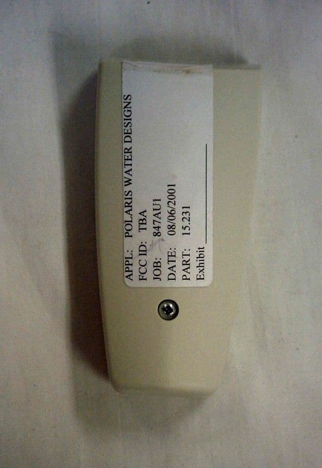
Click to zoom
Application Details
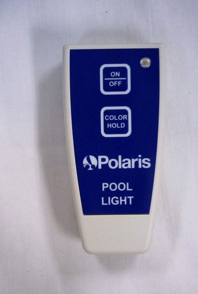
- Equipment Class
- DSC - Part 15 Security/Remote Control Transmitter
- Date of Grant
- Sep 13, 2001
- Application Purpose
- Original Equipment
- Date of Application
- Sep 13, 2001
- Equipment Note
- Pool Light
- Frequency Range
- 433.80000000 - 434.80000000
- Company
- Polaris Pool Systems, Inc.
- Country
- United States
Documents & Files
Document Text
Text extracted from the exhibit documents filed with the FCC. Open a document above to read the original.
Users Manual
FORM PE1017 Copyright 2001 Polaris Pool Systems’ Wireless Remote Control For Underwater Pool Lighting Installation and Operator’s Manual (ii) Contents Installation.................................. 1 Operator’s Instructions.................. 4 Changing Batteries........................ 7 Troubleshooting............................ 8 (iii) FCC STATEMENT THIS DEVICE COMPLIES WITH PART 15 OF THE FCC RULES. OPERATION IS SUBJECT TO THE FOLLOWING TWO CONDITIONS: (1) THIS DEVICE MAY NOT CAUSE HARMFUL INTERFERENCE, AND (2) THIS DEVICE MUST ACCEPT ANY INTERFERENCE RECEIVED, INCLUDING INTERFERENCE THAT MAY CAUSE UNDESIRED OPERATION. NOTE: The manufacturer is not responsible for radio or TV interference caused by unauthorized modifications to this equipment. Such modifications could void the user’s authority to operate this equipment. Wireless Remote Control For Underwater Pool Lighting FCC ID: PFUPE1012 (1) Installation 1. Remove the cover of the Pool Light Control Module by removing the necessary screws (Figure A). (Insert Figure A Here) (2) 2. Remove the Wireless Remote Control receiver module (Figure B) from it’s packaging and press it firmly into the designated socket on the Pool Light Control Module (Figure C). (Figure B Here) (Figure C Here) (3) 3. Route the Wireless Remote Control receiver module’s antenna (Figure D) through the hole in the cover of the Pool Light Control Module. Replace the Pool Light Control Module cover and screws. For best performance, make sure the antenna is straight, pointed upward, and not touching any metal. (Insert Figure D Here) (4) Operator’s Instructions Turning the Pool Light On and Off On the Wireless Remote Control, press the “On/Off” button (Figure E) once to turn the Pool Light ON. The light will continually sequence through a pattern of colors. Press the “On/Off” button again to turn the Pool Light OFF. (Insert Figure E Here) (5) Operator’s Instructions Pausing the Pool Light at a Desired Color The Pool Light must be ON for this feature. Press the “HOLD” button (Figure E) once on the Wireless Remote Control. The Pool Light will stop changing colors and remain at its present color. To display a different color, press the “HOLD” button and the Pool Light will begin to change colors, press the “HOLD” button again to stop the Pool Light at desired color. (6) Operator’s Instructions Precautions The Wireless Remote Control is designed to be water resistant. However, severe damage may result if the unit is completely submerged under water. Do not use the Wireless Remote Control in the pool or as a pool toy. Should the Wireless Remote Control inadvertently fall into the pool, it will float. Please exercise safety and remove the unit from the pool as soon as possible. (7) Changing Batteries The handheld Wireless Remote Control operates on two “AAA” batteries. To change the batteries, remove the screw from the back of the unit (Figure F). Remove the back cover, being careful not to disconnect any electrical connections. Replace the two “AAA” batteries. Note the location of the “+” symbol on the batteries (Figure G), the unit will not function if the batteries are installed backwards. Figure F Here Figure G Here (8) Troubleshooting Symptom Action Intermittent Operation or Decreased Range of Operation 1) Make sure antenna is straight and pointed upward. 2) Make sure antenna does not contact metal surfaces. 3) Replace Batteries (p.7) 4) Hold transmitter at 45 degree angle while pressing buttons. Does not work at all 1) Make sure Installation is correct. 2) Replace batteries. 3) Contact a qualified electrician for diagnosis. (9) Copyright 2001 Polaris Pool Systems, Inc. 10453 Tillery Road Springhill, FL 34608
ID Label/Location Info
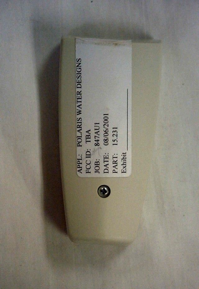
THIS DEVICE COMPLIES WITH PART 15 OF THE FCC RULES. OPERATION IS SUBJECT TO THE FOLLOWING TWO CONDITIONS: (1) THIS DEVICE MAY NOT CAUSE HARMFUL INTERFERENCE, AND (2) THIS DEVICE MUST ACCEPT ANY INTERFERENCE RECEIVED, INCLUDING INTERFERENCE THAT MAY CAUSE UNDESIRED OPERATION. POLARIS POOL SYSTEMS, INC. FCC ID: PFUPE1012 MODEL: PE1012
ID Label/Location Info
Wednesday, September 12, 2001 19:17:03
Operational Description
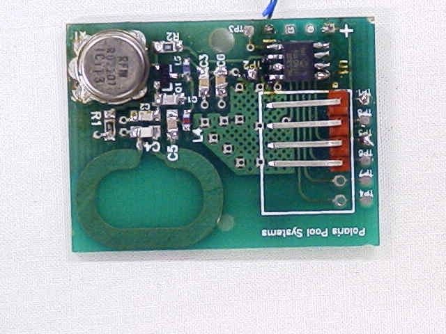
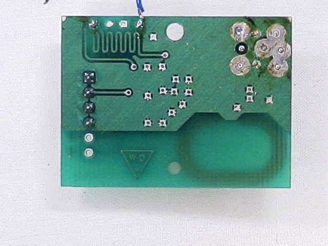
Transmitter – PE1012 Circuit Description The transmitter is powered by two AAA size batteries in series yielding 3.0V operating voltage to the transmitter circuit. Employed in this product is the Keeloq™ technology by Microchip, containing a rolling code algorithm. The 8-bit Keeloq™ processor has four (4) function inputs yielding a total of 15 possible switching functions. The output of this processor modulates the oscillatory circuit, which has a surface acoustical wave (SAW) resonator at 433.92 MHz. The resultant signal switches the high- frequency NPN transistor, and subsequently, an inductive trace (the antenna) balanced with inductors and capacitors. Receiver – PE1013 Circuit Description A quarter-wave antenna of solid copper wire brings the received signal into the receiver board and immediately into a surface acoustical wave (SAW) filter centered about 433.92MHz and impedance-matched on both ends. The output of the SAW is impedance matched into the input of the canned RF device for demodulation. This particular device, the Micrel MICRF011BM, is programmable for either super heterodyne or super regenerative modes of operation. Since we are utilizing a tight tolerance SAW resonator on the transmitter, we are able to choose to operate this device in the fixed frequency, single-conversion super heterodyne mode of operation and thus recognize possible performance improvements over the super regenerative mode of operation. The MICRF011BM outputs demodulated audio data directly to an 8-bit microcontroller. Along with various logical functions, the microcontroller employs the Keeloq™ decoding algorithm to decode the receive signal and translate the contained information to the four (4) outputs of the microcontroller. The four (4) outputs of the microcontroller mimic the four (4) inputs to the transmitter’s Keeloq™ encoder. With more hardware, one can easily recognize up to 15 functions with these four outputs. A non-volatile memory is used on the receiver to store mated transmitter serial numbers along with certain secret manufacturer’s codes used as seeds in the decryption algorithm. Lastly, a means by which to program new transmitters to the receiver is supplied through a digital input which must be grounded to activate the learn process and a digital output to display the status via an external LED.
Test Report
TABLE OF CONTENTS APPLICANT: POLARIS POOL SYSTEMS, INC. FCC ID: PFUPE1012 TEST REPORT CONTAINING: PAGE 1.............TEST EQUIPMENT LIST & TEST PROCEDURE PAGE 2.............TEST PROCEDURE CONTD. PAGE 3.............RADIATION INTERFERENCE TEST DATA PAGE 4.............CALCULATION OF DUTY CYCLE PAGE 5.............DUTY CYCLE PLOT – SMALL PULSES PAGE 6.............DUTY CYCLE PLOT – LARGE PULSES PAGE 7A-B..........DUTY CYCLE PLOT PAGE 8.............OCCUPIED BANDWIDTH PAGE 9.............OCCUPIED BANDWIDTH PLOT EXHIBIT ATTACHMENTS: EXHIBIT 1A-B........BLOCK DIAGRAM EXHIBIT 2A-B........SCHEMATIC EXHIBIT 3...........PARTS LIST EXHIBIT 4A-4L.......INSTRUCTION MANUAL EXHIBIT 5...........FCC ID LABEL SAMPLE EXHIBIT 6...........SKETCH OF FCC ID LABEL LOCATION EXHIBIT 7...........FRONT VIEW EXTERNAL PHOTO EXHIBIT 8...........REAR VIEW EXTERNAL PHOTO EXHIBIT 9...........COMPONENT SIDE INTERNAL PHOTO EXHIBIT 10..........COPPER SIDE INTERNAL PHOTO EXHIBIT 11..........TEST SET UP PHOTO EXHIBIT 12..........CIRCUIT DESCRIPTION APPLICANT: POLARIS POOL SYSTEMS, INC. FCC ID: PFUPE1012 REPORT #: P\POLARIS\847AU1\847AU1RPT.doc PAGE: TABLE OF CONTENTS LIST APPLICANT: POLARIS POOL SYSTEMS, INC. FCC ID: PFUPE1012 TEST EQUIPMENT LIST 1. Spectrum Analyzer: HP 8566B-Opt 462, S/N 3138A07786, w/ preselector HP 85685A, S/N 3221A01400, Quasi-Peak Adapter HP 8565OA, S/N 3303A01690 & Preamplifier HP 8449B-OPT H02, S/N 3008A00372 2. Biconnical Antenna: Eaton Model 94455-1, S/N 1057 3. Biconnical Antenna: Electro-Metrics Model BIA-25, S/N 1171 4. Log-Periodic Antenna: Electro-Metrics Model EM-6950, S/N 632 5. Log-Periodic Antenna: Electro-Metrics Model LPA-30, S/N 409 6. Double-Ridged Horn Antenna: Electro-Metrics Model RGA-180, 1-18 GHz, S/N 2319 7. 18-26.3GHz Systron Donner Standard Gain Horn #DBE-520-20 8. Horn 40-60GHz: ATM Part #19-443-6R 9. Line Impedance Stabilization Network: Electro-Metrics Model ANS-25/2, S/N 2604 10. Temperature Chamber: Tenney Engineering Model TTRC, S/N 11717-7 11. Frequency Counter: HP Model 5385A, S/N 3242A07460 12. Peak Power Meter: HP Model 8900C, S/N 2131A00545 13. Open Area Test Site #1-3meters 14. Signal Generator: HP 8640B, S/N 2308A21464 15. Signal Generator: HP 8614A, S/N 2015A07428 16. Passive Loop Antenna: EMCO Model 6512, 9KHz to 30MHz, S/N 9706-1211 17. Dipole Antenna Kit: Electro-Metrics Model TDA-30/1-4, S/N 153 18. AC Voltmeter: HP Model 400FL, S/N 2213A14499 19. Digital Multimeter: Fluke Model 8012A, S/N 4810047 20. Digital Multimeter: Fluke Model 77, S/N 43850817 21. Oscilloscope: Tektronix Model 2230, S/N 300572 TEST PROCEDURE GENERAL: This report shall NOT be reproduced except in full without the written approval of TIMCO ENGINEERING, INC. RADIATION INTERFERENCE: The test procedure used was ANSI STANDARD C63.4-1992 using a HEWLETT PACKARD spectrum analyzer with a prese- lector. The bandwidth of the spectrum analyzer was 100 kHz with an appropriate sweep speed. The analyzer was calibrated in dB above a microvolt at the output of the antenna. The resolution bandwidth was 100KHz and the video bandwidth was 300KHz. The ambient temperature of the UUT was 88ºF with a humidity of 60%. REPORT #: P\POLARIS\847AU1\847AU1RPT.doc PAGE #: 1 TEST PROCEDURES CONTD. FORMULA OF CONVERSION FACTORS: The Field Strength at 3m was estab- lished by adding the meter reading of the spectrum analyzer (which is set to read in units of dBuV) to the antenna correction factor sup- plied by the antenna manufacturer. The antenna correction factors are stated in terms of dB. The gain of the Preselector was accounted for in the Spectrum Analyzer Meter Reading. Example: Freq (MHz) METER READING + ACF = FS 33 20 dBuV + 10.36 dB = 30.36 dBuV/m @ 3m ANSI STANDARD C63.4-1992 10.1.7 MEASUREMENT PROCEDURES: The UUT was placed on a table 80 cm high and with dimensions of 1m by 1.5m. The UUT was placed in the center of the table. The table used for radiat- ed measurements is capable of continuous rotation. The spectrum was scanned from 30 MHz to 10th harmonic of the fundamental. Peak readings were taken in three (3) orthogonal planes and the high- est readings were converted to average readings based on the duration of "ON" time. Measurements were made by TIMCO ENGINEERING INC. at the registered open field test site located at 849 N.W. State Road 45, Newberry, Fl 32669. When an emission was found, the table was rotated to produce the maximum signal strength. At this point, the antenna was raised and lowered from 1m to 4m. The antenna was placed in both the horizontal and vertical planes. APPLICANT: POLARIS POOL SYSTEMS, INC. FCC ID: PFUPE1012 REPORT #: P\POLARIS\847AU1\847AU1RPT.doc PAGE #: 2 APPLICANT: POLARIS POOL SYSTEMS, INC. FCC ID: PFUPE1012 NAME OF TEST: RADIATION INTERFERENCE RULES PART NO.: 15.231 REQUIREMENTS: Fundamental Field Strength Field Strength of Frequency of Fundamental Harmonics and Spurious MHz dBuV Emissions (dBuV/m @ 3m) 40.66 to 40.70 67.04 47.04 70 to 130 61.94 41.94 130 to 174 61.94 to 71.48 41.94 to 51.48 174 to 260 71.48 51.48 260 to 470 71.48 to 81.94 51.48 to 61.94 470 and above 81.94 61.94 THE LIMIT FOR AVERAGE FIELD STRENGTH dBuV/m FOR THE FUNDAMENTAL FREQUENCY= 80.82 dBuV/m. NO FUNDAMENTAL IS ALLOWED IN THE RESTRICTED BANDS. THE LIMIT FOR AVERAGE FIELD STRENGTH dBuV/m FOR THE HARMONICS AND SPURIOUS FREQUENCIES = 60.82 dBuV/m. SPURIOUS IN THE RESTRICTED BANDS MUST BE LESS THAN 54dBuV/m OR 15.209. Emission Frequency MHz Meter Reading dBuv Ant. Polarity Coax Loss dB Correction Factor dB Duty Cycle Factor dB Field Strength dBuv/m Margin dB 433.80 62.7 H 3.10 16.98 15.00 67.58 13.24 867.70 34.3 V 4.20 22.22 15.00 45.66 15.17 1,301.50 ** 40.8 V 3.00 25.85 15.00 53.92 0.08 1,735.40 32.0 H 3.00 27.20 15.00 46.92 13.90 2,169.20 31.2 V 3.80 28.42 15.00 47.76 13.07 2,603.10 29.0 V 3.80 29.51 15.00 46.99 13.83 3,036.90 10.7 V 4.80 30.59 15.00 30.13 30.69 3,470.80 15.8 V 4.80 31.68 15.00 36.75 24.07 3,904.60 ** 10.4 V 4.80 32.76 15.00 32.86 21.14 4,338.50 ** 21.1 V 6.20 33.38 15.00 44.75 9.25 SAMPLE …
Text truncated - open the document above for the full version.
Contact Information
Applicant
Jesse Loden(Sr. Electronics Engineer)
Test Firm
Timco Engineering, Inc.S Sanders
Technical Specifications
| # | Rule Parts | Frequency Range | Power Output |
|---|---|---|---|
| 1 | 15.231 | 433.8 MHz - 434.8 MHz | - |
Other Applications from Polaris Pool Systems, Inc.
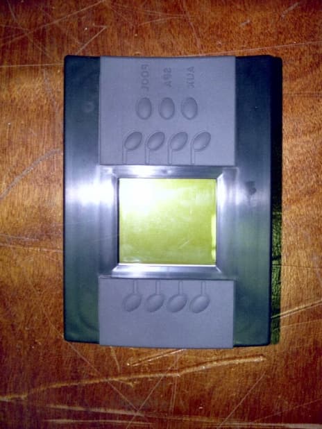
PFU-12-200X
Jan 26, 2001Wireless Pool/Spa Controller
Equipment Class
DXT - Part 15 Low Power Transceiver, Rx Verified