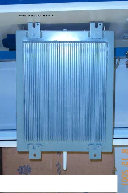
PFVCSPICE001Frequency Translating Repeater System
Littlefeet, Inc.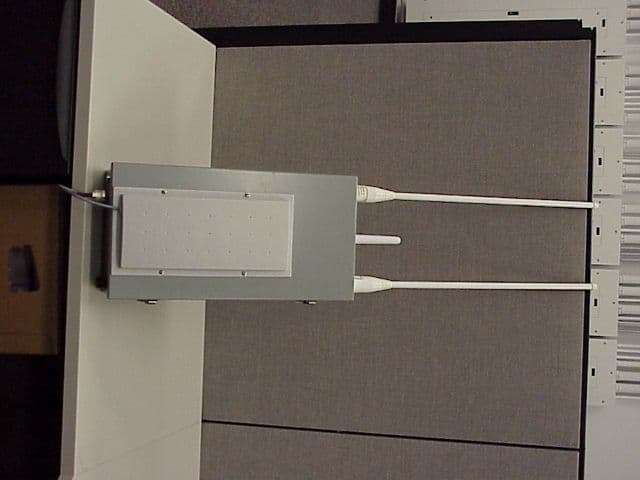
Click to zoom
Application Details
- Equipment Class
- PCB - PCS Licensed Transmitter
- Date of Grant
- May 21, 2001
- Application Purpose
- Original Equipment
- Date of Application
- Jan 17, 2001
- Equipment Note
- Frequency Translating Repeater System
- Frequency Range
- 1850.20000000 - 1909.80000000
- Company
- Littlefeet, Inc.
- Country
- United States
Documents & Files
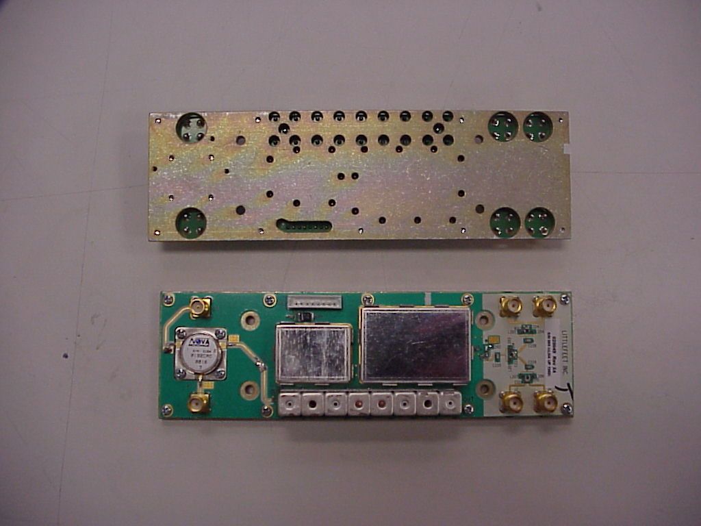
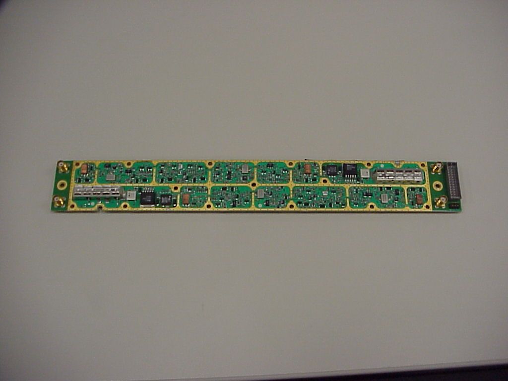
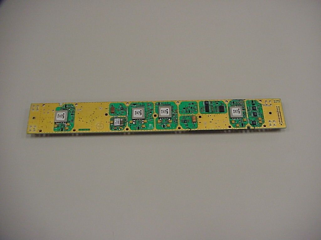
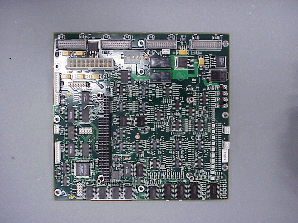
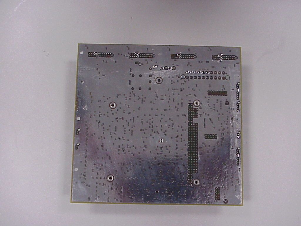
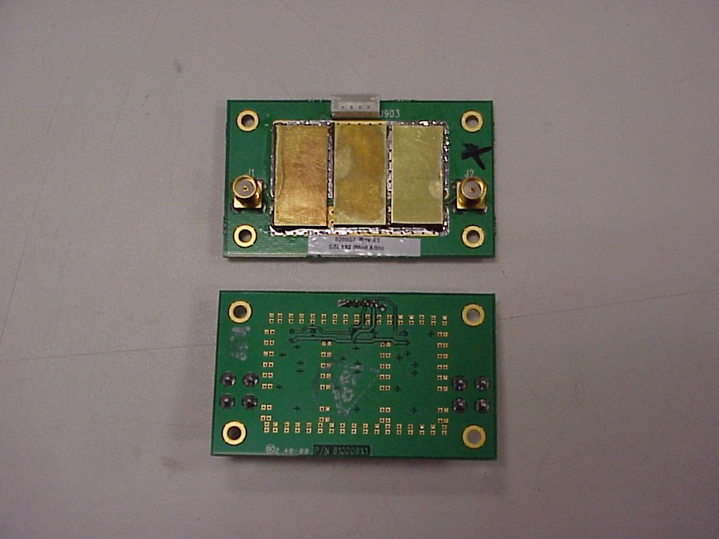
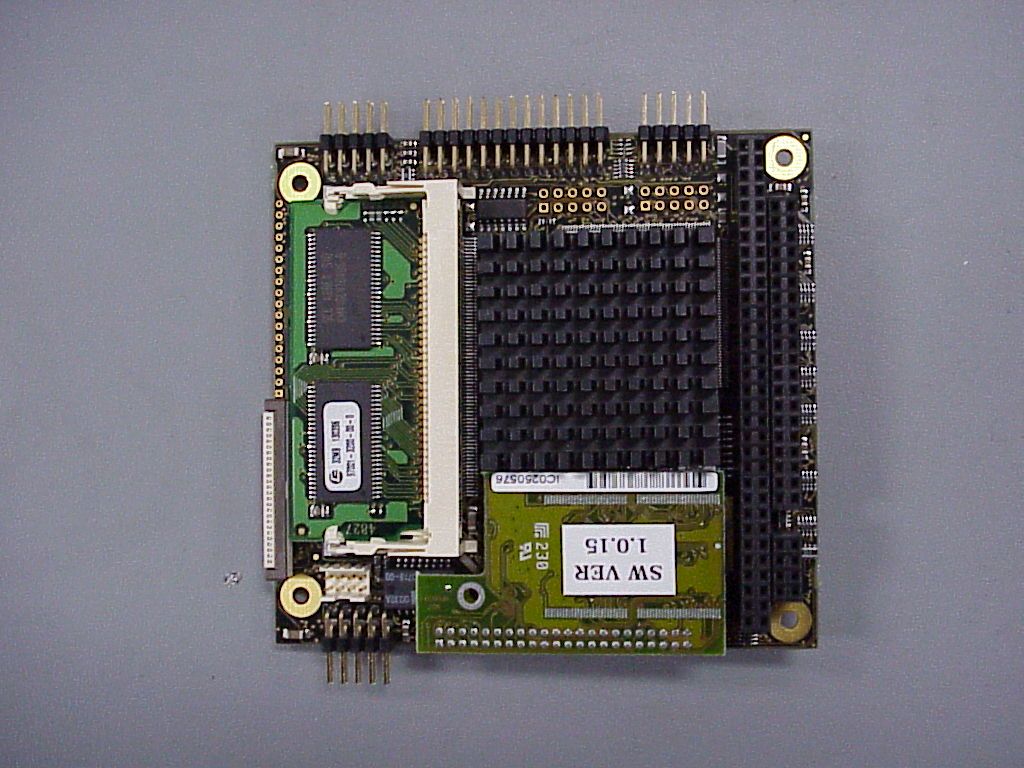
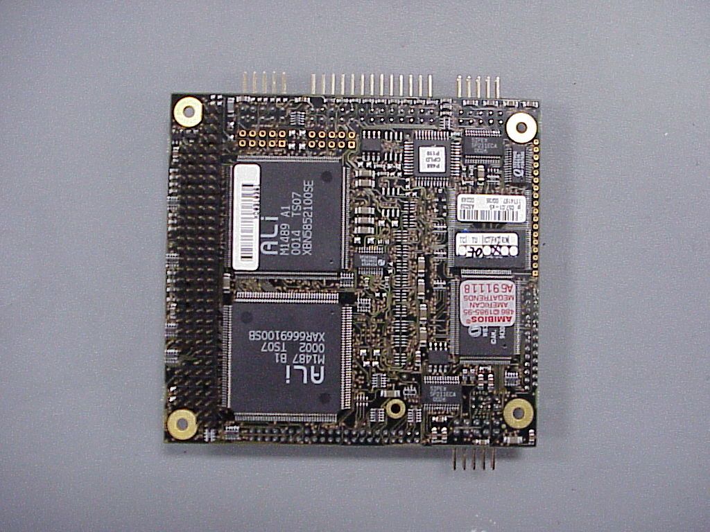
Document Text
Text extracted from the exhibit documents filed with the FCC. Open a document above to read the original.
Users Manual
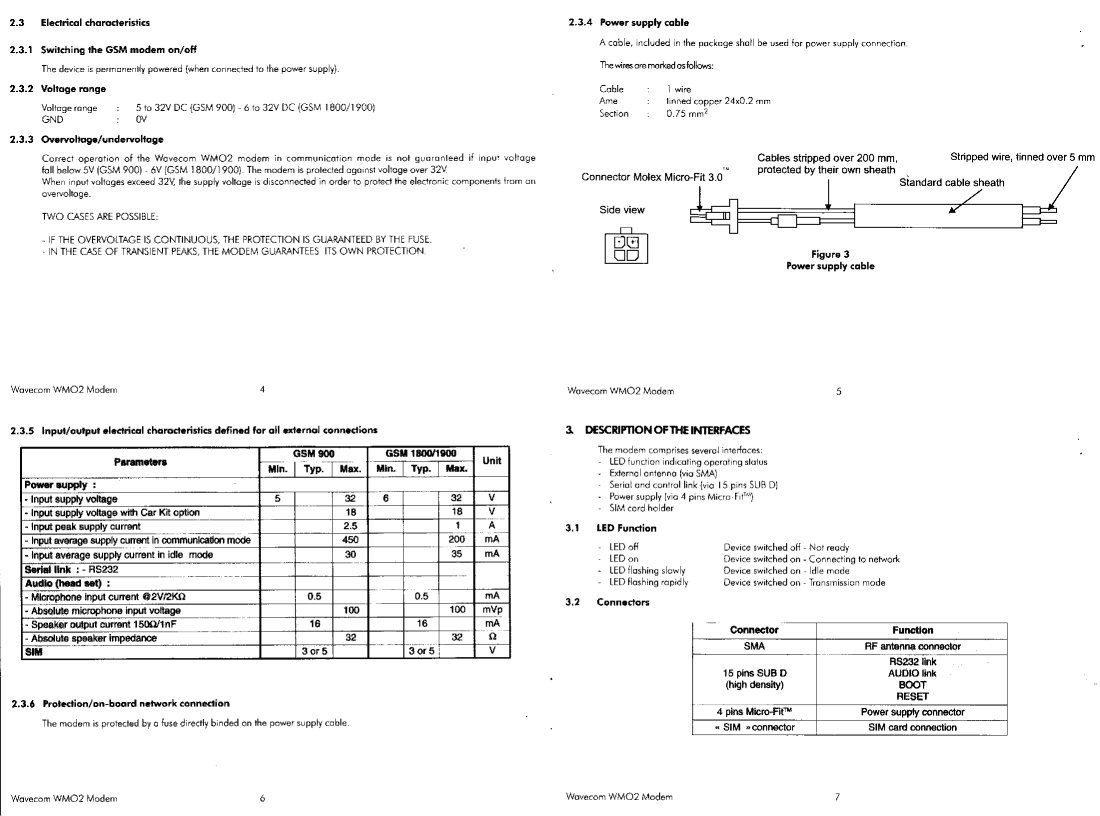
SPICE HARDWARE GUIDE a guide to installing and using SPICE hardware littlefeet ™ , inc. January, 2000 The information in this document is subject to change without notice. Littlefeet is not responsible for errors contained in this document, nor for incidental or consequential damages in connection with the use of this manual. Copyright © 2000, Littlefeet, Inc. All rights reserved. Littlefeet, SPICE, bSPICE, cSPICE, OMC-SPICE, SST are registered trademarks of Littlefeet, Inc. Adobe and Acrobat Reader are trademarks of Adobe Systems Incorporated. Cisco, Cisco Systems, and the Cisco Systems logo are trademarks or registered trademarks of Cisco Systems, Inc. or its affiliates. This material is not sponsored by, endorsed by, or affiliated with Cisco Systems, Inc. Sun, SPARC and Solaris are trademarks of the Sun Microsystems, Inc. UNIX is a registered trademark of X/Open Company Limited. Microsoft and Windows are registered trademarks of Microsoft Corporation. All other products or services mentioned in this manual are covered by the trademarks, service marks, or product names as designated by the companies who market those products. Littlefeet, Inc. 13000 Gregg Street Poway, CA 92064 858.375.6400 www.littlefeet-inc.com Document Number: 550001 Littlefeet, Inc.iii ZERO contents ONEintroduction1 about Littlefeet, Inc. . . . . . . . . . . . . . . . . . . . . . . . . . . . . . . . . . . . . . . . . . . . . . . . . . . 1 about this documentation . . . . . . . . . . . . . . . . . . . . . . . . . . . . . . . . . . . . . . . . . . . . . 1 TWOsystem overview3 concepts and terminology . . . . . . . . . . . . . . . . . . . . . . . . . . . . . . . . . . . . . . . . . . . . . 3 system components . . . . . . . . . . . . . . . . . . . . . . . . . . . . . . . . . . . . . . . . . . . . . . . . . . . . . 4 THREEinstalling SPICE5 concepts and terminology . . . . . . . . . . . . . . . . . . . . . . . . . . . . . . . . . . . . . . . . . . . . . 5 installation overview . . . . . . . . . . . . . . . . . . . . . . . . . . . . . . . . . . . . . . . . . . . . . . . . . . . . . 6 installation equipment. . . . . . . . . . . . . . . . . . . . . . . . . . . . . . . . . . . . . . . . . . . . . . . . . . . . 7 installing bSPICE. . . . . . . . . . . . . . . . . . . . . . . . . . . . . . . . . . . . . . . . . . . . . . . . . . . . . . . . 8 install modem antenna . . . . . . . . . . . . . . . . . . . . . . . . . . . . . . . . . . . . . . . . . . . . . . . . 9 install dessicant . . . . . . . . . . . . . . . . . . . . . . . . . . . . . . . . . . . . . . . . . . . . . . . . . . . . . 9 install power supply . . . . . . . . . . . . . . . . . . . . . . . . . . . . . . . . . . . . . . . . . . . . . . . . . . 9 mount the unit . . . . . . . . . . . . . . . . . . . . . . . . . . . . . . . . . . . . . . . . . . . . . . . . . . . . . 11 connect power . . . . . . . . . . . . . . . . . . . . . . . . . . . . . . . . . . . . . . . . . . . . . . . . . . . . . 11 notify OMC . . . . . . . . . . . . . . . . . . . . . . . . . . . . . . . . . . . . . . . . . . . . . . . . . . . . . . . . 13 installing cSPICE . . . . . . . . . . . . . . . . . . . . . . . . . . . . . . . . . . . . . . . . . . . . . . . . . . . . . . . 14 verify site . . . . . . . . . . . . . . . . . . . . . . . . . . . . . . . . . . . . . . . . . . . . . . . . . . . . . . . . . 15 install coverage antennas . . . . . . . . . . . . . . . . . . . . . . . . . . . . . . . . . . . . . . . . . . . . . 20 install dessicant . . . . . . . . . . . . . . . . . . . . . . . . . . . . . . . . . . . . . . . . . . . . . . . . . . . . 21 install power supply . . . . . . . . . . . . . . . . . . . . . . . . . . . . . . . . . . . . . . . . . . . . . . . . . 22 determine link antenna orientation. . . . . . . . . . . . . . . . . . . . . . . . . . . . . . . . . . . . . . 22 mount the unit . . . . . . . . . . . . . . . . . . . . . . . . . . . . . . . . . . . . . . . . . . . . . . . . . . . . . 24 check alignment . . . . . . . . . . . . . . . . . . . . . . . . . . . . . . . . . . . . . . . . . . . . . . . . . . . . 27 ground unit. . . . . . . . . . . . . . . . . . . . . . . . . . . . . . . . . . . . . . . . . . . . . . . . . . . . . . . . 27 connect power . . . . . . . . . . . . . . . . . . . . . . . . . . . . . . . . . . . . . . . . . . . . . . . . . . . . . 28 notify OMC . . . . . . . . . . . . . . . . . . . . . . . . . . . . . . . . . . . . . . . . . . . . . . . . . . . . . . . . 29 FOURcommissioning and maintenance31 operation overview . . . . . . . . . . . . . . . . . . . . . . . . . . . . . . . . . . . . . . . . . . . . . . . . . . . . . 33 commission bSPICE . . . . . . . . . . . . . . . . . . . . . . . . . . . . . . . . . . . . . . . . . . . . . . . . . . . . 34 connect link antenna . . . . . . . . . . . . . . . . . . . . . . . . . . . . . . . . . . . . . . . . . . . . . . . . 34 ZEROSPICE Hardware Guide contents550001 ivLittlefeet, Inc. connect BTS to RF input . . . . . . . . . . . . . . . . . . . . . . . . . . . . . . . . . . . . . . . . . . . . . 35 waterproof connections . . . . . . . . . . . . . . . . . . . . . . . . . . . . . . . . . . . . . . . . . . . . . . 35 connect laptop to the unit . . . . . . . . . . . . . . . . . . . . . . . . . . . . . . . . . . . . . . . . . . . . . . . . 36 Ethernet connection . . . . . . . . . . . . . . . . . . . . . . . . . . . . . . . . . . . . . . . . . . . . . . . . . 36 modem dial-in . . . . . . . . . . . . . . . . . . . . . . . . . . . . . . . . . . . . . . . . . . . . . . . . . . . . . 37 replace SIM card. . . . . . . . . . . . . . . . . . . . . . . . . . . . . . . . . . . . . . . . . . . . . . . . . . . . . . . 38 replace batteries . . . . . . . . . . . . . . . . . . . . . . . . . . . . . . . . . . . . . . . . . . . . . . . . . . . . . . . 39 FIVEsafety and standards41 concepts and terminology . . . . . . . . . . . . . . . . . . . . . . . . . . . . . . . . . . . . . . . . . . . . 41 RF exposure . . . . . . . . . . . . . . . . . . . . . . . . . . . . . . . . . …
Text truncated - open the document above for the full version.
Cover Letter(s)
13000 Gregg Street Poway, California 92064 Tel: 858.375.6400 Fax: 858.375-6401 www.littlefeet-inc.com April 3, 2001 FCC Application Processing Branch RE: FCC ID PFVCSPICE001 731 Confirmation Number: EA99785 REQUEST FOR CONFIDENTIALITY Littlefeet, Inc. is a start up company with an innovative design that will soon be offered for sale to the Telecommunications Industry. The documentation submitted to the FCC for Product Certification under 47CFR Part 24, describes and illustrates our design. We have patents pending and wish to prevent competition from copying our design before patents are in place to protect us. The following documents are considered proprietary and company confidential. This request for confidentiality applies to the following documents. Block Diagram.pdf 810095 - c-Spice RF Schematic 810069 - c-Spice Controller interface Schematic 810049 - c-Spice LNA Uplink Schematic 810049-02 - c-Spice LNA Downlink Schematic 810057 – Spice Modem Attenuator BOM 010010-04 - ASSY, TOP, CSPICE,GSM, 1900 Sincerely, Lou Guerin Agency Approvals Manager Littlefeet, Inc. [email protected]
ID Label/Location Info
Label for cSpice units NOTES: 1. MATERIAL: MEETS UL STANDARD UL969 2. TEXT COPY: MUST PASS RUB TEST (15 SECONDS WITH MINERAL SPIRITS, ISOPROPYL ALCOHOL, OR GASOLINE AND 15 SECONDS WITH W ATER) 3. ADHESIVE: MUST WITHSTAND MAXIMUM = 60°C (140°F), MINIMUM = -40°C (-40°F) AND SUITABLE FOR APPLICATION TO POLYESTER URETHANE POWDER COATED SURFACE 4. DIMENSIONS: TOLERANCE ± 0.05” 5. PACKAGING: ? Littlefeet, Inc. Poway, California 92064 (858) 375-6400 Created by D. Wade January 11, 2001 5100XX REV X1 FCC ID : MODEL NO.GD1901C 5100XX X1 PFVCSPICE001 TUV/ NRTL PATENT PENDING Littlefeet, Inc. Poway, California 92064 (858) 375-6400 Website: www.littlefeet-inc.com Made in U.S.A. SERIAL NO.XXXXXXXX 2.75” 4.0” Input Voltage: 20-56 VDC Input Current:
ID Label/Location Info
NOTES: 1. MATERIAL: MEETS UL STANDARD UL969 2. TEXT COPY: MUST PASS RUB TEST (15 SECONDS WITH MINERAL SPIRITS, ISOPROPYL ALCOHOL, OR GASOLINE AND 15 SECONDS WITH W ATER) 3. ADHESIVE: MUST WITHSTAND MAXIMUM = 60°C (140°F), MINIMUM = -40°C (-40°F) AND SUITABLE FOR APPLICATION TO POLYESTER URETHANE POWDER COATED SURFACE 4. DIMENSIONS: TOLERANCE ± 0.05” 5. PACKAGING: ? Littlefeet, Inc. Poway, California 92064 (858) 375-6400 Created by D. Wade January 11, 2001 5100XX REV X1 This device complies with Part 15 of the FCC rules. Operation is subject to the followi ng two conditio ns: (1) This de vice ma y no t ca use harmful interference, and (2) this device must accept any interference i ncludi ng interference that may cause undesired operation. 5100XX X1 4.0 0.6
Operational Description
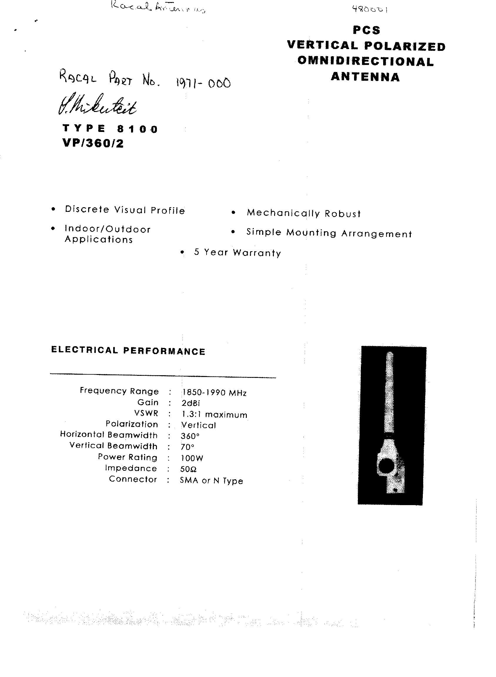
PCS - Omnidirectional Fixed Station AntennasPage 1 of 3 http://www.antenna.com/pcs/sd-1262.html11/10/2000 Omnidirectional Fixed Station Antennas For Wireless Local Loop and PCS-1900 Applications ASPRM2972 • ASPRM2973 • ASPRM2976 Precision Engineered – provides high conductivity for low- loss and highly efficient operation through end fed design with integral broadband matching section Lightweight – versatile mounting options allow for effortless and rapid high-volume deployment. No ground plane required Customized – available in OEM packages for similar applications or alternative gain levels. Custom options include connector types, mounting configurations and jumper cables Durable – high quality fiberglass construction withstands extreme weather conditions for trouble-free service Versatile – covers a variety of applications from spread spectrum to wireless local loop DC Grounded – dissipates static and/or reduces the potential of electromagnetically induced currents into the coaxial feed system from nearby lightning strikes* Unobtrusive – blends easily into surrounding environment with slim, low-profile, aesthetically pleasing housing. Ideal alternative when zoning issues are a concern * Based on IEEE standard 80 for fusing current of the shunt. Direct lightning strikes or other high voltage applied to elements not covered. Specifications ASPRM2972ASPRM2973ASPRM2976 Electrical Frequency Range 1850-1990 MHz1850-1990 MHz1850-1990 MHz VSWR 1.9:11.9:11.5:1 Gain 3 dBd/5 dBi4 dBd/6 dBi6 dBd/8 dBi Power 10 watts10 watts10 watts Beamwidth (E- plane @ -3 dB) 32° 21° 12° Polarization VerticalVerticalVertical PCS - Omnidirectional Fixed Station AntennasPage 2 of 3 http://www.antenna.com/pcs/sd-1262.html11/10/2000 Mounting Options Input Impedance 50 ohms50 ohms50 ohms Termination N femaleN femaleN female Mechanical Overall Length 10 inches (25.4 cm) 14.5 inches (36.8 cm) 24 inches (60.9 cm) Wind Area 0.012 ft 2 (0.001 m 2 ) 0.023 ft 2 (0.003 m 2 ) 0.044 ft 2 (0.004 m 2 ) Weight 0.25 lb (0.11 kg) 0.38 lb (0.17 kg) 0.44 lb (0.20 kg) Shipping Weight 0.50 lb (0.22 kg) 0.60 lb (0.27 kg) 0.70 lb (0.32 kg) Radome OD 0.5 inches (1.3 cm) 0.5 inches (1.3 cm) 0.5 inches (1.3 cm) Maximum Wind Speed 129 mi/h (208 km/h) 129 mi/h (208 km/h) 129 mi/h (208 km/h) Radiator Material Brass and Copperworld™ Brass and Copperworld™ Brass and Copperworld™ Radome Enclosure Fiber glassFiber glassFiber glass Weather Protection O-ring seal at ferrule O-ring seal at ferrule O-ring seal at ferrule Standard Bulkhead Mount Alternate Bulkhead Mount Optional K-920 mounting bracket available separately PCS - Omnidirectional Fixed Station AntennasPage 3 of 3 http://www.antenna.com/pcs/sd-1262.html11/10/2000 Omnidirectional Patterns Antenna Specialists • An Allen Telecom Company 31225 Bainbridge Road • Cleveland, Ohio 44139-2281 Phone: 440-349-8400 • Fax: 1-800-321-9978 or 440-349-8404 Cable Mount Optional K-920 mounting bracket available separately Cable Mount Optional K-921 adjustable mounting bracket available separately ASPRM2972 ASPRM2973 ASPRM2976
Operational Description
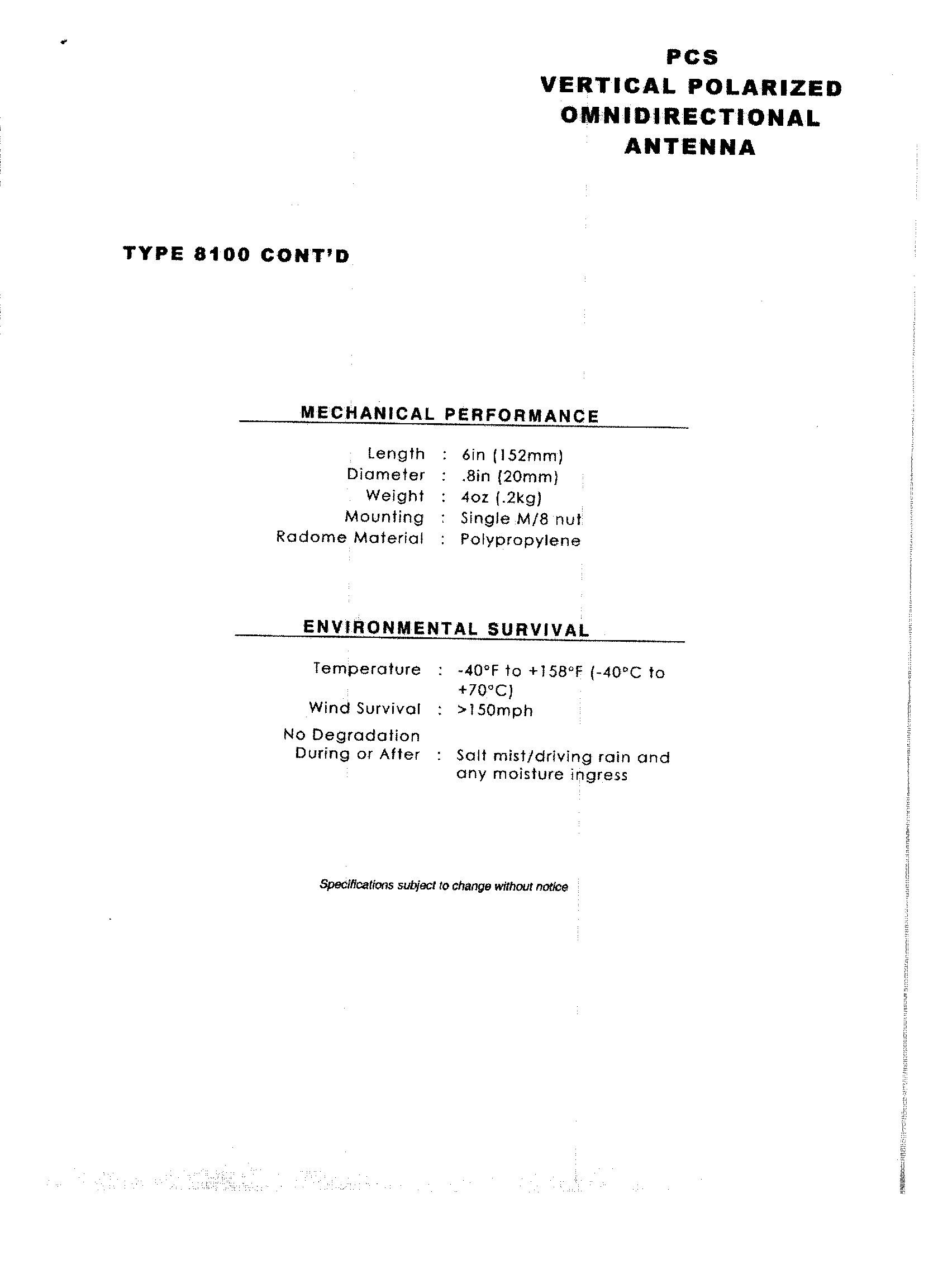
Redhawk User’s Guide & Technical Specification v.00I7/2/99 This document is in DRAFT format and is subject to change at Omnipoint Technologies sole discretion at any time. .......... . . . . . . . Wireless Solutions Division Omnipoint Technologies, Inc. Redhawk TM User’s Guide and Technical Manual GSM Wireless Terminal Wireless Solutions Division Omnipoint Technologies, Inc. 1365 Garden of the Gods Road Colorado Springs, CO 80907 www.omnipoint-tech.com Redhawk User’s Guide & Technical Specification v.00I7/2/99 This document is in DRAFT format and is subject to change at Omnipoint Technologies sole discretion at any time. 2 Important Safety Information Some of the following information may not apply to all devices described in this manual. However, precautions should be observed when handling any electrical device. ♦ Save this manual, it contains important safety information and operating instructions. ♦ Do not expose this product to open flames. ♦ Care should be taken so that liquids do not spill into the devices. ♦ Connection to AC power should only be performed by a qualified electrician. ♦ Do not attempt to disassemble the product. Doing so will void warranty. This product does not contain consumer serviceable components. (This does not apply to Subscriber Identification Modules (SIMs)). Guidelines for Limiting RF Exposure The Redhawk TM products are a radio transmitter and receiver intended for fixed and mobile uses only. They comply with the RF hazard requirements applicable to fixed PCS equipment operating under the authority of 47 CFR Part 24, Subpart E of the FCC Rules and Regulations when installed properly. The Redhawk TM products comply with FCC requirements for Human Exposure by meeting these requirements: 1. The device’s antenna must be installed no closer than 20 cm to any person. 2. Only fixed and mobile applications are permitted. 3. Portable applications (within 20 cm of any person) are strictly prohibited. 4. Antenna gain is limited to a maximum of 7 dBi for fixed applications. 5. Antenna gain is limited to a maximum of 3 dBi for mobile applications. NOTE: Care must be taken by the installer and/or user of the Redhawk TM products to ensure proper antenna selection and installation. Adherence to the above conditions is necessary to comply with FCC requirements for safe operation regarding exposure to RF radiation. The Redhawk TM products may be operated in a desktop environment. The user must take special precautions to ensure the 20 cm proximity limit for distance from the antenna to any person is maintained. Redhawk User’s Guide & Technical Specification v.00I7/2/99 This document is in DRAFT format and is subject to change at Omnipoint Technologies sole discretion at any time. 3 Redhawk TM User’s Guide and Technical Manual GSM Wireless Modem INTRODUCTION ........................................................................................................................................... 5 GSM Overview ................................................................................................................................. 6 Technical Specifications ............................................................................................................................ 7 Physical ............................................................................................................................................ 7 Environmental .................................................................................................................................. 9 Interfaces ....................................................................................................................................... 10 Status Indication............................................................................................................................. 12 Modes of Operation................................................................................................................................... 13 Circuit Switched Data ..................................................................................................................... 13 SMS ............................................................................................................................................... 13 USSD ............................................................................................................................................. 14 VOICE ............................................................................................................................................ 14 SOFTWARE INTERFACE.......................................................................................................................... 15 AT Command Set .......................................................................................................................... 15 DTM Initialization and Setup Examples ......................................................................................... 18 Troubleshooting ........................................................................................................................................ 22 Glossary/Acronyms................................................................................................................................... 23 Appendix a: Regulatory Information ..................................................................................................... 25 FCC Part 15 Compliance ............................................................................................................... 25 Human Exposure Compliance .......................................................................................................25 NRTL Approval............................................................................................................................... 26 GSM 1900 Type Approval / Type Certification .........................................................................…
Text truncated - open the document above for the full version.
RF Exposure Info
Doc Number: 22011-00 Revision: 1.0 Date: 11 May 2001 Page: 1of: 20 Original Issue: 10 Jan 2000 Littlefeet, inc. Initiator: Graeme White Title: SPICE FCC Maximum Permissible Exposure (MPE) Analysis Report Approval: Graeme WhiteTitle: Director, Systems Engineering This document analyses the expected SPICE system RF radiation exposure levels. Distribution: Engineering: Dan, Keith, Kris, Sam, Ram, Jay, David, Don, David Bissonette Sales/Marketing: Stefan, Fraser, Hang Operations/Field Services: Tim Littlefeet Confidential and Proprietary Littlefeet, Inc.Confidential and Proprietary2 Document Revision History Document No.Subject Department 0 RevDescription of ChangesChange DateAuthor 0.1Draft created10 Jan 2000Graeme White 1.0FCC MPE Analysis11 May 2000David Bissonette SPICE RF Radiation Exposure Analysis XXXXX-XX Systems Engineering Littlefeet, Inc.Confidential and Proprietary3 Table of Contents 1Executive Summary.................................................................................................................. 4 2Abbreviations............................................................................................................................ 5 3Objective................................................................................................................................... 6 4Introduction.............................................................................................................................. 7 5Prediction Method.................................................................................................................... 9 6Power Density Comparisons................................................................................................... 10 7Discussion...............................................................................................................................16 8Conclusion.............................................................................................................................. 17 9References.............................................................................................................................. 18 Littlefeet, Inc.Confidential and Proprietary4 1 Executive Summary This document presents the radio frequency exposure analysis results of the Littlefeet SPICE product. The analysis focused on independently calculating radio frequency exposure levels for each unit in the two-unit SPICE system. Each unit is capable of transmitting four GSM RF channels and one integrated modem GSM RF channel. Each unit was analyzed under maximum output power (worst-case) scenarios. This approach ensures FCC compliance under all operating conditions. The FCC Maximum Permissible Exposure (MPE) regulation specifies two exposure criteria for occupational and general population limits. More specifically, occupational limit is 50 W/m 2 and general population limit is 10 W/m 2 . Each of these exposure power density limits is expressed for specified exposure durations. Occupational and general population exposure at these power densities is specified at durations of 6 minutes and 30 minutes respectively. The calculations performed by Littlefeet determined the FCC compliance distance for FCC Maximum Permissible Exposure (MPE). Calculation results indicate bSPICE compliance for occupational and general population is 0.57 m and 1.27 m respectively. Calculation results indicate cSPICE compliance for occupational and general population is 0.19 m and 0.43 m respectively. Littlefeet, Inc.Confidential and Proprietary5 2 Abbreviations SPICE Small Profile Intelligent Coverage Element BCCH Broadcast Control Channel RBS Base Transceiver Station GSM Global System for Mobile Communications ANSI American National Standards Institute RF Radio Frequency PCS Personal Communication System BSPICE Littlefeet Base SPICE Unit CSPICE Littlefeet Coverage SPICE Unit Littlefeet, Inc.Confidential and Proprietary6 3 Objective The objective of this document is to present calculated data for the electromagnetic radiation exposure levels in close proximity to the SPICE system RF emitting entities. The analysis will be restricted to the PCS spectrum. Littlefeet, Inc.Confidential and Proprietary7 4 Introduction Concerns have been raised worldwide about the possibility of adverse health effects arising from exposure to RF radiation. RF radiation, as well as near ultraviolet radiation, visible light, infrared radiation and power frequency fields, are types of non-ionizing radiation. These, together with ionizing electromagnetic radiation (X-rays, gamma rays and higher frequency ultraviolet rays), make up the electromagnetic spectrum. Ionizing radiation is of most concern, since it has the potential to destroy or alter human tissue and damage DNA. Non-ionizing radiation does not interact with human tissue in the same way as ionizing radiation. However, resonance interactions are possible with non-ionizing radiation. The depth of penetration and sites of absorption are dependent upon the wavelength of the energy. PCS frequencies (1.9 to 2 GHz) produce non-ionizing RF radiation. Research has shown that the resonance interactions produced by RF radiation can only cause the molecules in biological material to vibrate and thereby generate heat. Efforts to determine whether RF radiation affects biological cells, other than through heat, are inconclusive. It is obviously preferable to minimize the duration and magnitude of any RF radiation exposure for members of the general population, especially as there is still significant research being conducted throughout the world on other possible health risks associated with RF radiation exposure. This document addresses power density in terms of Maximum Permissible Exposure (MPE) for both Occupational/Controlled Exposure and General Population/Uncontrolled Exposure as described in the FCC Regulations. The SPICE system is a low power infrastructure solution for the wireless industry. The BSPICE and CS…
Text truncated - open the document above for the full version.
Test Report
Garwood Laboratories, Inc.Garwood Laboratories, Inc. - World Compliance Division Electromagnetic Compatibility Document No. FR1526 EUT: bSPICE / cSPICE Date: January 2, 2001 Page 1 of 44 EMC Measurement / Technical Report FCC Test Specification : FCC Part 24 - Personal Communications Services Subpart E – Broadband PCS Equipment Authorization : Certification Manufacturer : Littlefeet, Inc. Equipment Under Test : Small Profile Intelligent Coverage Element Model bSPICE Model cSPICE Test Report No. : FR1526 Purchase Order No. : E2072781A Document History Revision Issue Date Affected Pages Description of Modifications Revised By Approved By N/C January 2, 2001 Initial release 1. March 15, 20001 p. 44 Clause 6.3 Intermodulation Attenuation data sheets were inserted in Appendix C – Attachment Section. Garwood Laboratories, Inc.Garwood Laboratories, Inc. - World Compliance Division Electromagnetic Compatibility Document No. FR1526 EUT: bSPICE / cSPICE Date: January 2, 2001 Page 2 of 44 EMC Measurement / Technical Report Document No. FR1526 From Garwood Laboratories, Inc. World Compliance Division Test for Littlefeet, Inc. Small Profile Intelligent Coverage Element Model bSPICE / cSPICE Test Personnel Test Dates Kieth Vu - EMC Test Engineer 24, 26, 27, 31 October 2000 Test Facility Address City, State, Zip Code Phone Fax Garwood Laboratories, Inc.-OC 565 Porter Way Placentia, CA 92870 (714) 572-2027 (714) 572-2025 This report may be reproduced in full, partial reproduction may only be made with the written consent of the laboratory. The results in this report pertain only to the specified equipment tested. This report may not be used to claim product endorsement by NVLAP or any agency of the U.S. government. Garwood Laboratories, Inc.Garwood Laboratories, Inc. - World Compliance Division Electromagnetic Compatibility Document No. FR1526 EUT: bSPICE / cSPICE Date: January 2, 2001 Page 3 of 44 TABLE OF CONTENTS MEASUREMENT/TECHNICAL REPORT SUMMARY...............................................................................4 1. GENERAL INFORMATION..................................................................................................................5 1.1 Product Description..........................................................................................................................5 1.2 Configuration of Tested System..........................................................................................................6 1.3 Test Facility.....................................................................................................................................7 2. PRODUCT LABELING .......................................................................................................................8 2.1 FCC ID Label..................................................................................................................................8 2.2 Location of Label on the EUT............................................................................................................8 2.3 Information to the User.....................................................................................................................8 3. BLOCK DIAGRAMS OF THE EUTs.....................................................................................................9 4. TEST RESULTS................................................................................................................................12 4.1 Ouput Power..................................................................................................................................12 4.2 Spurious Radiated Emissions............................................................................................................19 4.3 Spurious RF Conducted Emissions....................................................................................................20 4.4 Frequency Stability ........................................................................................................................29 4.5 Power Line Conducted Emissions.....................................................................................................31 4.5.1 Conducted Emissions Limits....................................................................................................31 4.5.2 Summary Table for Highest Conducted Emissions Levels............................................................31 4.6 Occupied Bandwidth.......................................................................................................................33 4.7 Crystal Access Restrictions...............................................................................................................37 5. PHOTOGRAPHS OF TEST ARRANGEMENTS..................................................................................38 APPENDIX A - TEST EQUIPMENT USED...........................................................................................42 APPENDIX B - SUPPLEMENTAL TEST DATA....................................................................................43 APPENDIX C - ATTACHMENTS...........................................................................................................44 Garwood Laboratories, Inc.Garwood Laboratories, Inc. - World Compliance Division Electromagnetic Compatibility Document No. FR1526 EUT: bSPICE / cSPICE Date: January 2, 2001 Page 4 of 44 MEASUREMENT / TECHNICAL REPORT SUMMARY Manufacturer Company Address City, State, Zip Country Contact Name Phone Fax Littlefeet, Inc. 13000 Gregg Street Poway, CA 92064 USA Dave Seden 858-375-6450 Not Available Type of Authorization Certification for Intentional Radiator Applicable FCC Rules This technical report is to certify that Equipment Under Test (EUT) complied with the requirements of: FCC Pt.24 – Personal Communications Services Subpart E – Broadband PCS All the tests necessary to show compliance to the requirements were performed and are listed below. RF…
Text truncated - open the document above for the full version.
Test Setup Photos
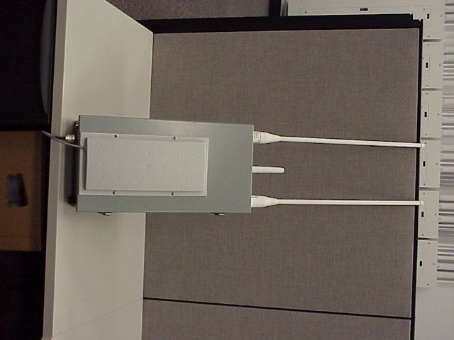
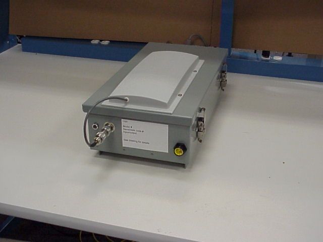
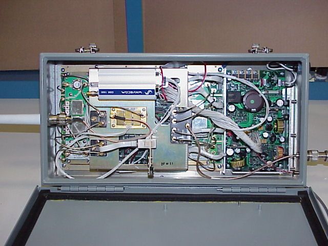
5 Photographs of Test Arrangements c SPICE Spurious Radiated Emissions (Front View) cSPICE Spurious Radiated Emissions (Rear View) c SPICE Test Setup (Front View) cSPICE Test Setup (Rear View) b SPICE Spurious Radiated Emissions (Front View) bSPICE Spurious Radiated Emissions (Rear View) b SPICE Test Setup (Front View) bSP…
Text truncated - open the document above for the full version.
Contact Information
Applicant
Mary Lou Guerin(Agency Approvals Manager)
Technical Contact
Garwood Laboratories, Inc.Arnie Tapia
[email protected]714-572-2027
13000 Gregg Street · Placentia, California · United States
Non-Technical Contact
Littlefeet, Inc.Mary Lou Guerin
[email protected]858-375-6427
Test Firm
Garwood Laboratories, Inc.Jason Armstrong
714-572-2027Fax: 714-572-2025
Technical Specifications
| # | Rule Parts | Frequency Range | Power Output | Emission | Tolerance |
|---|---|---|---|---|---|
| 3 | 24E | 1.85 GHz - 1.91 GHz | 1 W | 250KGXW | 0.1 ppm |
Other Applications from Littlefeet, Inc.
PFVBSPICE002
Sep 09, 2001BSpice 1900 MHz
Equipment Class
PCB - PCS Licensed Transmitter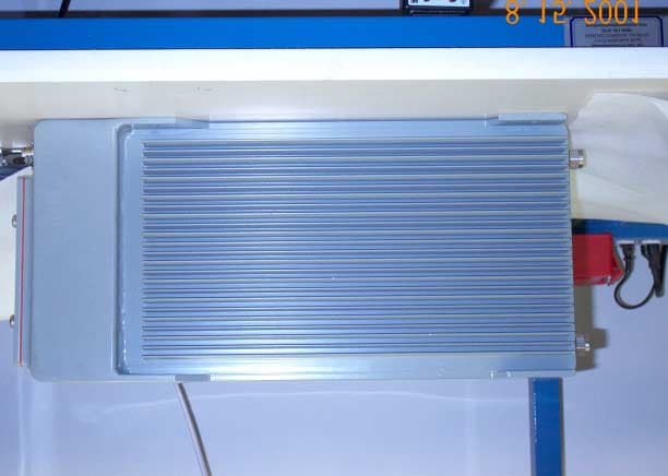
PFVCSPICE002
Sep 09, 2001CSpice 1900 MHz
Equipment Class
PCB - PCS Licensed Transmitter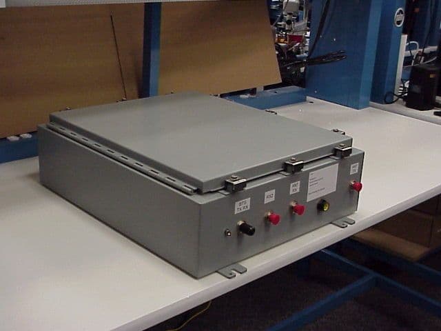
PFVBSPICE001
May 21, 2001Frequency Translating Repeater System
Equipment Class
PCB - PCS Licensed Transmitter