PFVCSPICE002CSpice 1900 MHz
Littlefeet, Inc.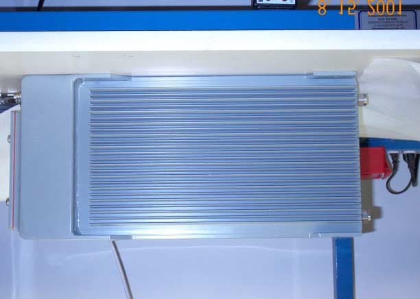
Click to zoom
Application Details
- Equipment Class
- PCB - PCS Licensed Transmitter
- Date of Grant
- Sep 09, 2001
- Application Purpose
- Original Equipment
- Date of Application
- Sep 09, 2001
- Equipment Note
- CSpice 1900 MHz
- Frequency Range
- 1930.00000000 - 1990.00000000
- Company
- Littlefeet, Inc.
- Country
- United States
Documents & Files
Document Text
Text extracted from the exhibit documents filed with the FCC. Open a document above to read the original.
Users Manual
P488m113.doc JUMPtec Industrielle Computertechnik AG Page: 1 of 38 MOPSlcd4 Technical Manual Rev. 1.3 JUMPtec Industrielle Computertechnik AG Brunnwiesenstraße 16 94469 Deggendorf/ Germany MOPSlcd4Table of Contents P488m113.doc JUMPtec Industrielle Computertechnik AG Page: 2 of 38 Table of Contents TABLE OF CONTENTS....................................................................................................................................2 USER INFORMATION......................................................................................................................................4 TRADEMARKS......................................................................................................................................................4 GENERAL...........................................................................................................................................................4 WARRANTY.........................................................................................................................................................5 INTRODUCTION....................................................................................................................................................5 FEATURES......................................................................................................................................................6 I/O MAP............................................................................................................................................................7 MEMORY MAP FOR BIOS, SSD AND JRC SUPPORT....................................................................................8 ONBOARD SSD (DOS-COMPATIBLE)............................................................................................................9 BLOCK DIAGRAM.........................................................................................................................................10 CONNECTOR ARRANGEMENT....................................................................................................................11 BIOS-DESCRIPTION......................................................................................................................................12 RTC-CMOS SETUP MENU.................................................................................................................................12 MAIN MENU......................................................................................................................................................12 STANDARD CMOS SETUP..................................................................................................................................12 ADVANCED CMOS SETUP.................................................................................................................................14 POWER MANAGEMENT SETUP.............................................................................................................................16 PERIPHERAL SETUP...........................................................................................................................................17 AUTO-DETECT HARD DISKS................................................................................................................................18 CHANGE USER PASSWORD................................................................................................................................18 CHANGE SUPERVISOR PASSWORD......................................................................................................................18 AUTO CONFIGURATION WITH OPTIMAL SETTINGS..................................................................................................18 AUTO CONFIGURATION WITH FAIL SAFE SETTINGS................................................................................................18 SAVE SETTINGS AND EXIT..................................................................................................................................18 EXIT WITHOUT SAVING......................................................................................................................................18 AMIBIOS CONFIGURATION SCREEN...................................................................................................................20 HARDWARE DESCRIPTION..........................................................................................................................21 ALI-CHIPSET FEATURES....................................................................................................................................21 MEMORY CONFIGURATION..................................................................................................................................21 INTERRUPTS.....................................................................................................................................................22 DMA...............................................................................................................................................................22 ONBOARD C&T VGA.........................................................................................................................................23 THE JIDA STANDARD........................................................................................................................................25 WATCHDOG EXTENSION.....................................................................................................................................28 NETWORK OPERATION................................................................................................................................29 OVERVIEW........................................................................................................................................................29 SPECIFICATIONS...................…
Text truncated - open the document above for the full version.
Users Manual
© 2000 Xircom, Inc. All rights reserved. All trademarks and copyrights are the property of Xircom, Inc. Formerly Omnipoint Technologies, Inc. Redhawk™ II GSM Wireless Terminal Users Guide Redhawk II GSM Modem Users Guide Draft: 10/30/002 Part Number: 07100020 version 00B © 2000 Xircom, Inc. All rights reserved. All trademarks and copyrights are the property of Xircom, Inc. SAFETY PRECAUTIONS Important Safety Information Some of the following information may not apply to all devices described in this manual. However, precautions should be observed when handling any electrical device. ! Save this manual, it contains important safety information and operating instructions. ! Do not expose the Redhawk II product to open flames. ! Care should be taken so that liquids do not spill into the devices. ! A qualified electrician should perform all primary connections to AC power. ! Do not attempt to disassemble the product. Doing so will void the warranty. With the exception of Subscriber Identification Modules (SIM), this product does not contain consumer serviceable components. Guidelines for Limiting RF Exposure The Redhawk II products are GSM radio transceivers, which operate under the authority of 47 CFR Part 24, Subpart E of the FCC Rules and Regulations. When installed and operated in accordance with the instructions provided in this manual, these devices comply with current FCC regulations regarding human exposure to radio frequency - electromagnetic fields. The following installation and operation restrictions apply to all Redhawk II products: ! These devices may only be used in fixed and mobile applications ! Portable applications, as defined by the FCC, are prohibited ! A separation distance of at least 20 cm (7 7/8) inches between the antenna and body of the user and other persons must be maintained at all times ! In FIXED applications antenna gain* is limited to a maximum of 7 dBi, with a corresponding equivalent isotropic radiated power (EIRP) of 37 dBm / 5 W ! In MOBILE applications antenna gain* is limited to a maximum of 3 dBi, with a corresponding equivalent isotropic radiated power (EIRP) of 33 dBm / 3 W ! Desktop and other uses of these devices where the antenna can easily be relocated are considered by the FCC to be mobile applications. * Antenna gain is defined as gain in dBi (dB referenced to an isotropic radiator) minus cabling loss. NOTE: Additional care must be taken by the installer and/or user of the Redhawk II TM products to ensure proper antenna selection and installation. Adherence to the above conditions is necessary to comply with FCC requirements for safe operation regarding exposure to RF radiation. Redhawk II GSM Modem Users Guide Draft: 10/30/003 Part Number: 07100020 version 00B © 2000 Xircom, Inc. All rights reserved. All trademarks and copyrights are the property of Xircom, Inc. Disclaimer The information and instructions contained within this publication comply with all FCC, NRLT, IMEI and other applicable codes in effect at the time of publication. Xircom, Inc. disclaims all responsibility for any act, or breach of law, code or regulation, including local or state codes, performed by a third party. Xircom strongly recommends that all installations, hookups, transmissions, etc. be performed by persons who are experienced in the fields of radio frequency technologies. Xircom acknowledges that the installation, setup and transmission guidelines contained within this publication are guidelines, and that each installation may have variables outside of the guidelines contained herein. Said variables must be taken into consideration when installing or using the product, and Xircom, Inc. shall not be responsible for installations or transmissions that fall outside of the parameters set forth in this publication. Xircom shall not be liable for consequential or incidental damages, injury to any person or property, anticipated or lost profits, loss of time, or other losses incurred by Customer or any third party in connection with the installation of the Products or Customer's failure to comply with the information and instructions contained herein. Beta Release Notes Data Services The current software release does not support transparent circuit switched data or Group 3 Fax. These services will be added in subsequent versions. AT Commands The current software version does not support all AT commands listed in this document. Please reference the attached Errata sheet for a list of the non- functioning AT commands. These commands will be added in future software versions. PUK Procedure The PUK procedure outlined in this document will be changing. Redhawk II GSM Modem Users Guide Draft: 10/30/004 Part Number: 07100020 version 00B © 2000 Xircom, Inc. All rights reserved. All trademarks and copyrights are the property of Xircom, Inc. DECLARATION OF CONFORMITY Xircom, Inc. of 2300 Corporate Center Drive, Thousand Oaks, CA 91360 declares that the Xircom Redhawk™ II GSM Radio Module, model 2110-1300 (900/1800) is in conformance with all relevant essential requirements of the European Council Directives listed below: 1999/5/ECRadio and Telecommunications Terminal Equipment Directive (Following Annex III of this Directive) 89/336/EECEMC Directive with Amendment 92/31/EEC and 93/68/EEC 72/23/EECLow Voltage Directive with Amendment 93/68/EEC This declaration is made based upon compliance to the following standards: EN 60950 (1992 w/ A1, 2, 3, 4)Safety of Information Technology Equipment, Including Electrical Business Equipment ETS 300 342-1 Edition 2 (June 1997)Radio Equipment and Systems (RES); Electromagnetic Compatibility (EMC) for European digital cellular telecommunications system (GSM 900 MHz and DCS 1800 MHz). Part 1: Mobile and portable radio and ancillary equipment. TBR 19 Edition 3 (October 1996)European digital cellular telecommunications system (Phase 2); Attachment requirements for global system for mobile communications (GSM) mobile stations; Access TBR 31 Edition …
Text truncated - open the document above for the full version.
Users Manual
SPICE ™ HARDWARE GUIDE a guide to installing and using SPICE hardware Hardware Release 1.5 September, 2001 550008 Rev. A The information in this document is subject to change without notice. Littlefeet is not responsible for errors contained in this document, nor for incidental or consequential damages in connection with the use of this manual. Copyright © 2001, Littlefeet, Inc. All rights reserved. Littlefeet, SPICE, bSPICE, cSPICE, and Out there are registered trademarks of Littlefeet, Inc. Adobe and Acrobat Reader are trademarks of Adobe Systems Incorporated. Microsoft and Windows are registered trademarks of Microsoft Corporation. All other products or services mentioned in this manual are covered by the trademarks, service marks, or product names as designated by the companies who market those products. Littlefeet, Inc. 13000 Gregg Street Poway, CA 92064 858.375.6400 www.littlefeet-inc.com Customer Support Toll-Free (US): 1.888.595.9444; Direct: +1 858.375.6443 [email protected] Document Number: 550008 Rev. A Approved per ECO C00545 Littlefeet, Inc.iii ZERO contents ONEintroduction1 about Littlefeet, Inc. . . . . . . . . . . . . . . . . . . . . . . . . . . . . . . . . . . . . . . . . . . . . . . . . . . 1 about this documentation . . . . . . . . . . . . . . . . . . . . . . . . . . . . . . . . . . . . . . . . . . . . . 1 TWOsystem overview3 concepts and terminology . . . . . . . . . . . . . . . . . . . . . . . . . . . . . . . . . . . . . . . . . . . . . 3 system components . . . . . . . . . . . . . . . . . . . . . . . . . . . . . . . . . . . . . . . . . . . . . . . . . . . . . 4 THREEsafety5 concepts and terminology . . . . . . . . . . . . . . . . . . . . . . . . . . . . . . . . . . . . . . . . . . . . . 5 RF exposure . . . . . . . . . . . . . . . . . . . . . . . . . . . . . . . . . . . . . . . . . . . . . . . . . . . . . . . . . . . 6 levels . . . . . . . . . . . . . . . . . . . . . . . . . . . . . . . . . . . . . . . . . . . . . . . . . . . . . . . . . . . . . 6 interference . . . . . . . . . . . . . . . . . . . . . . . . . . . . . . . . . . . . . . . . . . . . . . . . . . . . . . . . 6 unit safety . . . . . . . . . . . . . . . . . . . . . . . . . . . . . . . . . . . . . . . . . . . . . . . . . . . . . . . . . . . . . 7 water . . . . . . . . . . . . . . . . . . . . . . . . . . . . . . . . . . . . . . . . . . . . . . . . . . . . . . . . . . . . . 7 electrostatic discharge . . . . . . . . . . . . . . . . . . . . . . . . . . . . . . . . . . . . . . . . . . . . . . . . 7 lightning . . . . . . . . . . . . . . . . . . . . . . . . . . . . . . . . . . . . . . . . . . . . . . . . . . . . . . . . . . . 7 grounding. . . . . . . . . . . . . . . . . . . . . . . . . . . . . . . . . . . . . . . . . . . . . . . . . . . . . . . . . . 8 heights . . . . . . . . . . . . . . . . . . . . . . . . . . . . . . . . . . . . . . . . . . . . . . . . . . . . . . . . . . . . 8 clearances . . . . . . . . . . . . . . . . . . . . . . . . . . . . . . . . . . . . . . . . . . . . . . . . . . . . . . . . . 8 servicing the unit. . . . . . . . . . . . . . . . . . . . . . . . . . . . . . . . . . . . . . . . . . . . . . . . . . . . . . . . 9 wireless modem . . . . . . . . . . . . . . . . . . . . . . . . . . . . . . . . . . . . . . . . . . . . . . . . . . . . . 9 battery pack . . . . . . . . . . . . . . . . . . . . . . . . . . . . . . . . . . . . . . . . . . . . . . . . . . . . . . . . 9 power . . . . . . . . . . . . . . . . . . . . . . . . . . . . . . . . . . . . . . . . . . . . . . . . . . . . . . . . . . . . . 9 installation safety notes . . . . . . . . . . . . . . . . . . . . . . . . . . . . . . . . . . . . . . . . . . . . . . . . . 10 orientation . . . . . . . . . . . . . . . . . . . . . . . . . . . . . . . . . . . . . . . . . . . . . . . . . . . . . . . . 10 siting . . . . . . . . . . . . . . . . . . . . . . . . . . . . . . . . . . . . . . . . . . . . . . . . . . . . . . . . . . . . 10 general precautions. . . . . . . . . . . . . . . . . . . . . . . . . . . . . . . . . . . . . . . . . . . . . . . . . . . . . 12 FOURinstalling SPICE13 concepts and terminology . . . . . . . . . . . . . . . . . . . . . . . . . . . . . . . . . . . . . . . . . . . . 13 installation overview . . . . . . . . . . . . . . . . . . . . . . . . . . . . . . . . . . . . . . . . . . . . . . . . . . . . 14 installation equipment. . . . . . . . . . . . . . . . . . . . . . . . . . . . . . . . . . . . . . . . . . . . . . . . . . . 15 installing bSPICE. . . . . . . . . . . . . . . . . . . . . . . . . . . . . . . . . . . . . . . . . . . . . . . . . . . . . . . 16 ZERO: contentsSPICE™ Hardware Guide 550008 Rev. A ivLittlefeet, Inc. install power supply . . . . . . . . . . . . . . . . . . . . . . . . . . . . . . . . . . . . . . . . . . . . . . . . . 17 mount the unit . . . . . . . . . . . . . . . . . . . . . . . . . . . . . . . . . . . . . . . . . . . . . . . . . . . . . 20 run cables . . . . . . . . . . . . . . . . . . . . . . . . . . . . . . . . . . . . . . . . . . . . . . . . . . . . . . . . 23 connect power . . . . . . . . . . . . . . . . . . . . . . . . . . . . . . . . . . . . . . . . . . . . . . . . . . . . . 23 notify OMC . . . . . . . . . . . . . . . . . . . . . . . . . . . . . . . . . . . . . . . . . . . . . . . . . . . . . . . . 25 weatherproof . . . . . . . . . . . . . . . . . . . . . . . . . . . . . . . . . . . . . . . . . . . . . . . . . . . . . . 25 installing cSPICE. . . . . . . . . . . . . . . . . . . . . . . . . . . . . . . . . . . . . . . . . . . . . . . . . . . . . . . 26 install antennas . . . . . . . . . . . . . . . . . . . . . . . . . . . . . . . . . . . . . . . . . . . . . . . . . . . . 27 install power supply . . . . . . . . . . . . . . . . . . . . . . . . . . . . . . . . . . . . . . . . . . . . . . . . . 28 determine link antenna orientation . . . . . . . . . . . . . . . . . . . . . . . . . . . . . . . . . . . . . 29 mount the unit . . . . . . . . . . . . . . . . . . . . . . . . . . . . . . . . . . . . . . . . . . . . …
Text truncated - open the document above for the full version.
Attestation Statements
TÜV PRODUCT SERVICE 10040 Mesa Rim Road San Diego, CA 92121-2912 Phone 858 546 3999 FAX 858 546 0364 Report No. 105835-08 Page 52 Rev.No 1.0 ATTESTATION STATEMENT GENERAL REMARKS: SUMMARY: All tests were performed per FCC Part 2, Paragraphs 2.1046, 2.1049, 2.,1051, 2.1053, 2.1055(d)(1); Part 24, Paragraph 24,238. The Equipment Under Test n - Fulfills the requirements of FCC Part 2, Paragraphs 2.1046, 2.1049, 2.,1051, 2.1053, 2.1055(d)(1); Part 24, Paragraph 24,238. - TÜV PRODUCT SERVICE, INC. - Responsible Engineer: Dave Bernardin (EMC Engineer)
External Photos
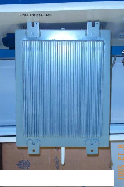
Cspice back Cspice bottom Cspice exterior CSPICE SIDE CSPICE TOP
Internal Photos
CSPICE INTERIOR C RF PWA BACK C RF PWA FRONT LNA DL PWA, BACK LNA UL PWA FRONT MDM ATTEN PWA FRONT/BACK CONTROL INT PWA BACK CONTROL INT PWA FRONT PC 104 ASSY BACK PC 104 ASSY FRONT DRAM BACK DRAM FRONT FLASH BACK FLASH FRONT JUMPTEC BACK JUMPTEC FRONT
Operational Description
13000 Gregg Street Poway, California 92064 Tel: 858.375.6400 Fax: 858.375-6401 www.littlefeet-inc.com August 14, 2001 Prepared by Lou Guerin SPICE Product description The product is a 1900MHz transceiver system for mobile phone telecommunication use. The product is known as SPICE 'Small Profile Intelligent Coverage Element’ with the designation of ‘bSPICE’ (base unit) and ‘cSPICE’ (coverage unit) and is defined as a ‘Frequency Translating Repeater System’. Each SPICE unit will have coverage and link frequencies assignable within its entire GSM frequency band. GSM 1900: 1850-1910 MHz paired with 1930-1990 MHz. The SPICE network is based upon a distributed coverage architecture, where the SPICE network provides the RF distribution functionality, but relies upon the underlying GSM system to provide the core functionality of the GSM system. This approach dictates that the SPICE network must be essentially transparent to the underlying GSM system. Operation: The bSPICE has antenna ports and interfaces directly with a third-party Base Transceiver Station (BTS) via cables; it can accommodate both duplexed and separate TX & RX connections. It translates the signal received from the BTS to a link frequency, usually a channel within the operator's band allocation. The bSPICE shall be capable of transmitting to a cluster of cSPICE located within the link range of 8km when the cSPICE is at a typical height of 30 meters. This link range assumes in-band back haul, flat terrain, and non Line-of-Sight conditions. The minimum separation between any channel frequencies (link or coverage) shall be 600 kHz. All external communications with the bSPICE shall be via an internal modem or equivalent modem chipset to allow setup, monitoring & reconfiguration. The maintenance and supervision of a network of SPICE Units will be performed by the OMC (Operation & Maintenance Center) system, resident at the network operator's central office. The cSPICE unit contains an integral antenna and receives its input signal on a link frequency from a bSPICE. It shifts that signal to the desired coverage frequency for transmission to the subscriber’s handset. No decoding is performed in the main signal path, only RF translation. It will typically be employed as part of a cluster that is simulcasting using an Omnidirectional Pattern (standard antenna) it provides coverage to the subscriber's handset and is located in the footprint of the coverage area. It may be part of a cluster of units that are simulating the same carriers, from the same BTS.
RF Exposure Info
Approved per ECO C00433 Littlefeet Confidential and Proprietary Doc Number: 740066 Revision: A Date: 13 July 01 Page: 1 of: 19 Original Issue: 13 July 2001 Littlefeet Inc. ENGINEERING REQUIREMENTS SPECIFICATION Author: Graeme White Title: R1.5 SPICE RF Radiation Exposure Analysis (FCC) Approval:Title: Content: This document analyses and presents the expected R1.5 (Las Vegas) SPICE system RF radiation exposure levels and compares them with the Maximum Permissible Exposure (MPE) limits specified by the FCC. Distribution: Engineering: Dan H., Graeme, Mike M., Kris, Lou Technology: Fraser Operations: Tim Roth Sales: VP, Sales R1.5 SPICE RF Radiation Exposure Analysis (FCC) Rev A Littlefeet, Inc.Confidential and ProprietaryPage 2 Document Revision History Document No. 740066 Subject R1.5 (Las Vegas) SPICE RF Radiation Exposure Analysis Department Systems Engineering RevDescription of ChangesChange DateAuthored By 0.1Draft for general review13 July 2001G. White AInitial Release25 July 2001G. White R1.5 SPICE RF Radiation Exposure Analysis (FCC) Rev A Littlefeet, Inc.Confidential and ProprietaryPage 3 Table of Contents 1I NTRODUCTION ............................................................................................................ 6 1.1S COPE .............................................................................................................................................. 6 1.2O VERVIEW ....................................................................................................................................... 6 1.3R EFERENCES ................................................................................................................................... 7 1.4A BBREVIATIONS AND A CRONYMS ................................................................................................... 8 2SPICE N ETWORK A RCHITECTURE ............................................................................ 9 3P REDICTION M ETHOD ............................................................................................... 11 4P REDICTION I NPUT P ARAMETERS ............................................................................. 14 5P OWER D ENSITY P REDICTIONS ................................................................................. 15 6R ATIO OF FCC MPE L IMITS TO P OWER D ENSITY .................................................. 17 7C ONCLUSION .............................................................................................................. 20 R1.5 SPICE RF Radiation Exposure Analysis (FCC) Rev A Littlefeet, Inc.Confidential and ProprietaryPage 4 List of Tables Table 1-1 FCC Maximum Permissible Exposure (MPE) Limits .................................................................... 7 Table 4-1 Prediction Input Parameters ......................................................................................................... 14 Table 5-1 bSPICE / cSPICE Site Power Densities ....................................................................................... 15 Table 6-1 Ratio of Power Density to FCC Occupational MPE Limit........................................................... 17 Table 6-2 Ratio of Power Density to FCC General Population MPE Limit ................................................. 17 R1.5 SPICE RF Radiation Exposure Analysis (FCC) Rev A Littlefeet, Inc.Confidential and ProprietaryPage 5 List of Figures Figure 2-1 SPICE Network Architecture ........................................................................................................ 9 Figure 3-1 cSPICE Enclosure ....................................................................................................................... 12 Figure 5-1 bSPICE Power Densities Versus FCC MPE Limits .................................................................... 16 Figure 5-2 cSPICE Power Densities Versus FCC MPE Limits .................................................................... 16 Figure 6-1 Ratio of Power Density to Occupational MPE Limit .................................................................. 19 Figure 6-2 Ratio of Power Density to General Population MPE Limit ........................................................ 19 R1.5 SPICE RF Radiation Exposure Analysis (FCC) Rev A Littlefeet, Inc.Confidential and ProprietaryPage 6 1 Introduction 1 1.1 Scope 2 This document presents predicted data for the electromagnetic radiation exposure levels 3 in close proximity to the SPICE system RF emitting devices. The predicted RF radiation 4 exposure levels will be compared with the Maximum Permissible Exposure (MPE) limits5 specified by the FCC. This analysis will be restricted to the SPICE PCS product line.6 1.2 Overview 7 Concerns have been raised worldwide about the possibility of adverse health effects8 arising from exposure to RF radiation. RF radiation, as well as near ultraviolet radiation, 9 visible light, infrared radiation and power frequency fields, are types of non-ionizing10 radiation. These, together with ionizing electromagnetic radiation (X-rays, gamma rays 11 and higher frequency ultraviolet rays), make up the electromagnetic spectrum. 12 Ionizing radiation is of most concern, since it has the potential to destroy or alter human 13 tissue and damage DNA. Non-ionizing radiation does not interact with human tissue in 14 the same way as ionizing radiation. Non-ionizing radiation causes resonance interactions 15 and research has shown that these interactions cause the molecules in biological material16 to vibrate and thereby generate heat. Efforts to determine whether RF radiation affects17 biological cells, other than through heat, are inconclusive.18 It is obviously preferable to minimize the duration and magnitude of any RF radiation19 exposure for members of the general population, especially as there is still significant20 research being conducted throughout the world on other possible health risks associated21 with RF radiation exposure. The SP…
Text truncated - open the document above for the full version.
Test Report
TÜV PRODUCT SERVICE 10040 Mesa Rim Road San Diego, CA 92121-2912 Phone 858 546 3999 FAX 858 546 0364 Report No. 105835-08 Page 1 Rev.No 1.0 MEASUREMENT AND TECHNICAL REPORT LITTLEFEET, INC. 13000 Gregg Street Poway, CA 92064 DATE: 03 August 2001 This Report Concerns:Original Grant: XClass II Change: Equipment Type:cSpice 1900 MHz, Model GL 1902C Deferred grant requested per 47 CFR 0.457(d)(1)(ii)?Yes: Defer until: No: X Company Name agrees to notify the Commission by:N/A of the intended date of announcement of the product so that the grant can be issued on that date. Transition Rules Request per 15.37?Yes:*No: X (*) FCC Part 2, Paragraphs 2.1046, 2.1049, 2.,1051, 2.1053, 2.1055(d)(1); Part 24, Paragraph 24,238 Report Prepared by: TÜV PRODUCT SERVICE 10040 Mesa Rim Road San Diego, CA 92121-2912 Phone: 858 546 3999 Fax: 858 546 0364 TÜV PRODUCT SERVICE 10040 Mesa Rim Road San Diego, CA 92121-2912 Phone 858 546 3999 FAX 858 546 0364 Report No. 105835-08 Page 2 Rev.No 1.0 TABLE OF CONTENTS Pages 1 GENERAL INFORMATION3 1.1Product Description3 1.2Related Submittal Grant5 1.3Tested System Details5 1.4Test Methodology5 1.5Test Facility6 1.6Part 2 Requirements7 2 SYSTEM TEST CONFIGURATION8 2.1Justification8 2.2EUT Exercise Software8 2.3Special Accessories8 2.4Equipment Modifications8 2.5Configuration of Tested System8 3RADIATED EMISSION EQUIPMENT/DATA9 Field Strength Calculation17 4 CONDUCTED EMISSION EQUIPMENT/DATA18 5ATTESTATION STATEMENT53 6LITTLEFEET INTERMODULATION DATA54 TÜV PRODUCT SERVICE 10040 Mesa Rim Road San Diego, CA 92121-2912 Phone 858 546 3999 FAX 858 546 0364 Report No. 105835-08 Page 3 Rev.No 1.0 1 GENERAL INFORMATION 1.1Product Description CSPICE 1900 MHz, Model GL1902C (Frequency Translating Repeater System) Power Requirements Regulations require testing to be performed at typical power ratings in the countries of intended use. (i.e., European power is typically 230 VAC 50 Hz or 400 VAC 50 Hz, single and three phase, respectively) Voltage:20-56 Vdc (If battery powered, make sure battery life is sufficient to complete testing.) # of Phases:N/A Current (Amps/phase(max)):5ACurrent (Amps/phase(nominal)): Other:External AC/DC power supply used to power EUT. Typical Installation and/or Operating Environment CSPICE will be installed outdoors on sides of buildings, roof tops, light poles. EUT Power Cable PermanentORXRemovableLength (in meters):2 meters typical ShieldedORXUnshielded EUT Interface Ports and Cables InterfaceShielding TypeTypeTermination Connector TypePort Termination Link AntennaX1XCaturCoaxialN Type50-OhmX Support Equipm…
Text truncated - open the document above for the full version.
Contact Information
Applicant
Mary Lou Guerin(Agency Approvals Manager)
Test Firm
TUV AmericaJames Owen
Technical Specifications
| # | Rule Parts | Frequency Range | Power Output | Emission | Tolerance |
|---|---|---|---|---|---|
| 2 | 24E | 1.93 GHz - 1.99 GHz | 5 W | 200KGXW | 0.05 ppm |
Other Applications from Littlefeet, Inc.
PFVBSPICE002
Sep 09, 2001BSpice 1900 MHz
Equipment Class
PCB - PCS Licensed Transmitter
PFVBSPICE001
May 21, 2001Frequency Translating Repeater System
Equipment Class
PCB - PCS Licensed Transmitter
PFVCSPICE001
May 21, 2001Frequency Translating Repeater System
Equipment Class
PCB - PCS Licensed Transmitter