PGK-P32VBUSB PC Camera
Look & Say Co., Ltd.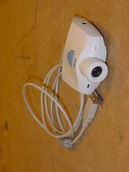
Click to zoom
Application Details
- Equipment Class
- JBP - Part 15 Class B Computing Device Peripheral
- Date of Grant
- Feb 22, 2001
- Application Purpose
- Original Equipment
- Date of Application
- Feb 22, 2001
- Equipment Note
- USB PC Camera
- Company
- Look & Say Co., Ltd.
- Country
- South Korea
Documents & Files
Document Text
Text extracted from the exhibit documents filed with the FCC. Open a document above to read the original.
Users Manual
LS-P32NB LS-A32NB LS-P32VB CONTENTS Chapter 1. InstallationChapter 2. Setting ‘Event’Chapter 3. CapVSudio ManualChapter 4. Q&AFCC INFO RMATION TO THE USERThis equipment has been tested and found to comply with the limits for a Class B digitaldevice, pursuant to part 15 of the FCC Rules. These limits are designed to provide reasonableprotection against harmful interference in a residential installation. This equipment generates,uses and can radiate radio frequency energy and, if not installed and used in accordance withthe instructions, may cause harmful interference to radio communications. However, there isno guarantee that interference will not occur in a particular installation. If this equipment does cause harmful interference to radio or television reception, which can be determined byturning the equipment off and on, the user is encouraged to try to correct the interference byone more of the following measures:-. Reorient or relocate the receiving antenna.-. Increase the separation between the equipment and receiver.-. Connect the equipment into an outlet on a circuit different from that to which the receiver is connected. -. Consult the dealer or an experienced radio/TV technician for help.WA RN INGChanges or modifications not expressly approved by the manufacturer could void the user’sauthority to operate the equipment . 2 1. Specifications ! 1/3” color VGA CMOS Image sensor ! 320k Pixels ! Lens F1.8, f=5.8 ! Snap Shot on the top ! VG A 15 Fps ! CIF 30Fps ! QCIF 30Fps 2. System Requirements ! Microsoft Windows 98, Windows ME, Windows 2000 ! Pentium MMX 200MHz or higher ! 32MB RAM or higher (64MB encouraged) ! 16bit color display or higher ! Connect to USB Port Chapter 1. Installation Install CapVstudio1. Shut down all running programs, including virus protection programs. Some virusprotection programs interfere with installation. Insert the L&S CD-ROM in yourcomputer’s CD-ROM Driver. Click the ‘CapVStudio Install’ to install and follow the onscreen prompts.2. Click ‘Next’..3. Dialogue box for selecting folder to be installed will appear. You may use defaultfolder, or click ‘Browse’ to specify other folder you want. 3 4. Type a new folder name, or select one from the existing Folder list. And click ‘Next’. 5. Dialogue box that notifies finishing the complete setup will appear. Install Driver1. To continue, click the ‘Driver Install’.Notice to take out the PC Camera from USB Port will appears before start install thedriver. If you didn’t connect PC Camera to USB port, click ‘OK’.The dialogue box that notifies the driver completely installed will appear as below. Ifyou use Windows 98, ME Operating system, please click ‘Yes’ to restart the system.After system is restarted, please connect the PC Camera to USB Port. 4 If you use Windows 2000 Operating system, you don’t need restart the system.Please connect the PC Camera to USB Port.Click ‘EXIT’ to finish the installation. Chapter 2 Setting ‘Event’1. To capture image by snapshot button on the top of PC camera, set the ‘Event’ asfollowings. Go to Control Panel, and then double click ‘Scanner & Camera’. 2. Select the ‘Look&Say USB Camera – ver 1. 57 ’, then click ‘Properties’.3. Select ‘Event’ tap, then Choose ‘New Picture Captured’ from the ‘CameraEvent ’ top-down menu. Check ONLY ‘CapVStudio Camera’ from the Application Listscreen of ‘Send to this application’. Then Click ‘Apply’ and ‘OK’ 5 * If ‘Event’ is not set, the extra Still Im age Capture window w ill appear. Chapter 3 CapVStudio Manual Studio ON/OFF Click the button ‘Studio ON/OFF’ to turn on or off the display window. Capturing Video .Studio ON/OFF Option He lp Viewing still imagealbum Capturing Still Image Capturing Video Viewing video album Quality/Speed Control Exit Display windows siz e Display window Album window for Moving picture Album window for Still image Select the folder to save the f and enter the file name 6 If you click the button ‘Capt uring Video’ the controlling box will appear. Please select the folder to save the file and enter the file name. And time duration(Default time : 5second), and check to the capture audio(If you like to). After finishedthe setting, then click ‘Capture’ to start video capturing. After completed capturingvideo, captured video file (in the form of AVI file format) w ill be saved in the video album automatically(Default - Save to : c:/program files/look&say/capvstudio/album/video/). Capturing Still Image Click t he button ‘Capturing Still Image’ to capture still im age. Select picture number, interval time, Color display to capture still image. For smaller data volume, selectlower bit color. For clearer picture, select higher bit color. After selected, click ‘Capture’. Captured image file w ill be saved in the still image album automatically. (Save to : c:/program files/look&say/capvstudio/album/picture/) Setting Options Click ‘Option’. Select one of two options to control the video format or video sources.Then click ‘OK’.After select the ‘Video Format’, the window will ap pear as above. Set up Frame Rate, Color space/Compression, Display Size. Then click ‘Apply’. Set up capturing timedu r at i o n Check to recordaudio 7 After select the ‘Video Source’, the window w ill appear as above. From the ‘Video Proc Amp’ tap, set up the suitable Configuration options with theplace using the PC camera. After finished setting, then click ‘Apply’.<For LS-A32NB / LS-P32NB / LS-D32NB Type PC Camera>Set White Balance to be automatic. (encouraging option)To use PC Camera outside click Outdoor’ and set up auto exposure / auto white balance Move the screen right to left(Mirror), up to down(Flip Vertically).To reduce flickers, set the suitable fluorescent lamp frequency . (In case of using in Korea, select 60Hz. In case of using in other country, selectnor mal fl uoresce nt lamp freq ue ncy which is suitable to use in the country.) Click ‘OK’.Control zoom value to zoom in the screen. On screen zoomed in, you can turn the screen focus right and left / up…
Text truncated - open the document above for the full version.
ID Label/Location Info
FCC ID. : PGK-P32VB ONETECH Testing & Evaluation Lab . IDENTIFICATION LABEL LOCATION: PROPOSED FCC ID LABEL The label of FCC ID. will be affixed to the bottom side of product. FCC ID FCC ID : PGK-P32VB Model Name: LS-P32VB This device complies with Part 15 of the FCC Rules. Operation is subject to the following two conditions: (1) this device may not cause harmful interference, and (2) this device must accept any interference received, including interference that may cause undesired operations LOOK & SAY CO., LTD Made in Korea
Test Report
Page 1 of 13 FCC ID. : Error! Unknown docume nt prope rty name . File No. : Error! Unknown docume nt prope rty name . This report shall not be reproduced except in full without our written approval.EMC-004 (Rev.0) HEAD OFFICE : #505 SK APT. Factory 223-28, Sangdaewon 1 Dong, Jungwon- Gu, Seongnam- C ity, K yunggi- Do, 462-121, Korea (TEL: 82- 31-746-8500 FAX: 82-31-746-8700 ) EM C Te s ting De pt : 426-1 Daessangryung- Ri, C howol- Myun, K wangju- K un, K yunggi- Do 464-860 Korea. (TEL: 82- 31-765-8289 FAX: 82-31-766-2904) ONETECH Testing & Evaluation Lab . ELECTROMAGNETIC EMISSION COMPLIANCE REPORT Test report file number : E012R-026 Applicant : LOOK & SAY CO., LTD. A ddre s s: 5F., Donghun Bldg., 733-22, Yeoksam-Dong, Kangnam-Gu, Seoul, 135-080, Korea Manufacturer : LOOK & SAY CO., LTD. A ddre s s: 5F., Donghun Bldg., 733-22, Yeoksam-Dong, Kangnam-Gu, Seoul, 135-080, Korea Type of Equipme nt : USB PC CAMERA (Pe riphe ral De vice for Class B Computing De vice ) FCC ID: PGK-P32VB Model / Type No. : LS-P32VB Se rial numbe r: N/ A Total page of Report: 13 pages (including this page) Date of Incoming: January 17, 2001 Date of Issuing : February 15, 2001 SUMMARY The equipment complies with the regulation; FCC PART 15 SUBPART B, SECTION 15.101 This test report contains only the results of a single test of the sample supplied for the examination. It is not a general valid assessment of the features of the respective products of the mass-production. Prepared by: Approved by: Y.K. Nam / Asst. Chief EngineerS. S. Hong / Managing Director EMC Dept.ONETECH Corp. ONETECH Corp. Page 2 of 13 FCC ID. : Error! Unknown docume nt prope rty name . File No. : Error! Unknown docume nt prope rty name . This report shall not be reproduced except in full without our written approval.EMC-004 (Rev.0) HEAD OFFICE : #505 SK APT. Factory 223-28, Sangdaewon 1 Dong, Jungwon- Gu, Seongnam- C ity, K yunggi- Do, 462-121, Korea (TEL: 82- 31-746-8500 FAX: 82-31-746-8700 ) EM C Te s ting De pt : 426-1 Daessangryung- Ri, C howol- Myun, K wangju- K un, K yunggi- Do 464-860 Korea. (TEL: 82- 31-765-8289 FAX: 82-31-766-2904) ONETECH Testing & Evaluation Lab . CONTENTS Page 1. VERIFICATION OF COMPLIANCE ................................................................................................................ 3 2. GENERAL INFORMATION .................................................................................................................................. 4 2.1 P RODUCT D ESCRIPTION ............................................................................................................................................. 4 2.2 R ELATED S UBMITTAL ( S ) / G RANT ( S ) ....................................................................................................................... 4 2.3 T EST S YSTEM D ETAILS .............................................................................................................................................. 5 2.4 T EST M ETHODOLOGY ................................................................................................................................................ 5 2.5 T EST F ACILITY ............................................................................................................................................................ 5 3. SYSTEM TEST CONFIGURATION ................................................................................................................... 6 3.1 J USTIFICATION ............................................................................................................................................................. 6 3.2 EUT EXERCISE S OFTWARE ........................................................................................................................................ 6 3.3 C ABLE D ESCRIPTION .................................................................................................................................................. 6 3.4 N OISE S UPPRESSION P ARTS ON C ABLE ................................................................................................................... 7 3.5 E QUIPMENT M ODIFICATIONS .................................................................................................................................... 7 3.6 C ONFIGURATION OF T EST S YSTEM .......................................................................................................................... 7 4. PRELIMINARY TEST .............................................................................................................................................. 8 4.1 AC P OWER LINE C ONDUCTED E MISSION T EST ..................................................................................................... 8 4.2 R ADIAT ED E MISSION T EST ........................................................................................................................................ 8 5. FINAL RESULT OF MEASURMENT ............................................................................................................... 9 5.1 C ONDUCTED E MISSION T EST .................................................................................................................................... 9 5.2 R ADIAT ED E MISSION T EST ...................................................................................................................................... 11 6. FIELD STRENGTH CALCULATION ............................................................................................................. 15 7. LIST OF TEST EQUIPMENT ............................................................................................................................. 16 Page 3 of 13 FCC ID. : Error! Unknown docume nt prope rty name . File No. : Error! Unknown docume nt prope rty name . This report shall not be reproduced except in full without our written approval.EMC-004 (Rev.0) HEAD OFFICE : #505 SK APT. Factory 223-28, Sa…
Text truncated - open the document above for the full version.
Test Setup Photos
Conducted Emission Test Radiated Emission Test
Contact Information
Applicant
Han-Won Jo(President)
Test Firm
ONETECH Corp.Y. Kwon
Technical Specifications
| # | Rule Parts | Frequency Range | Power Output |
|---|---|---|---|
| 1 | 15B | - | - |
Other Applications from Look & Say Co., Ltd.
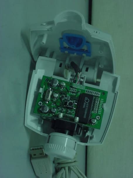
PGK-P32NB
Feb 08, 2001USB PC Camera
Equipment Class
JBP - Part 15 Class B Computing Device Peripheral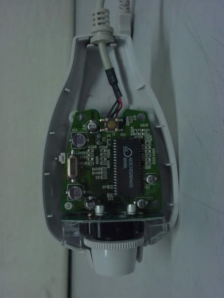
PGK-A32NB
Feb 08, 2001USB PC Camera
Equipment Class
JBP - Part 15 Class B Computing Device Peripheral