PGUFN802FHPropaq 802 LTRN
Welch Allyn, Inc.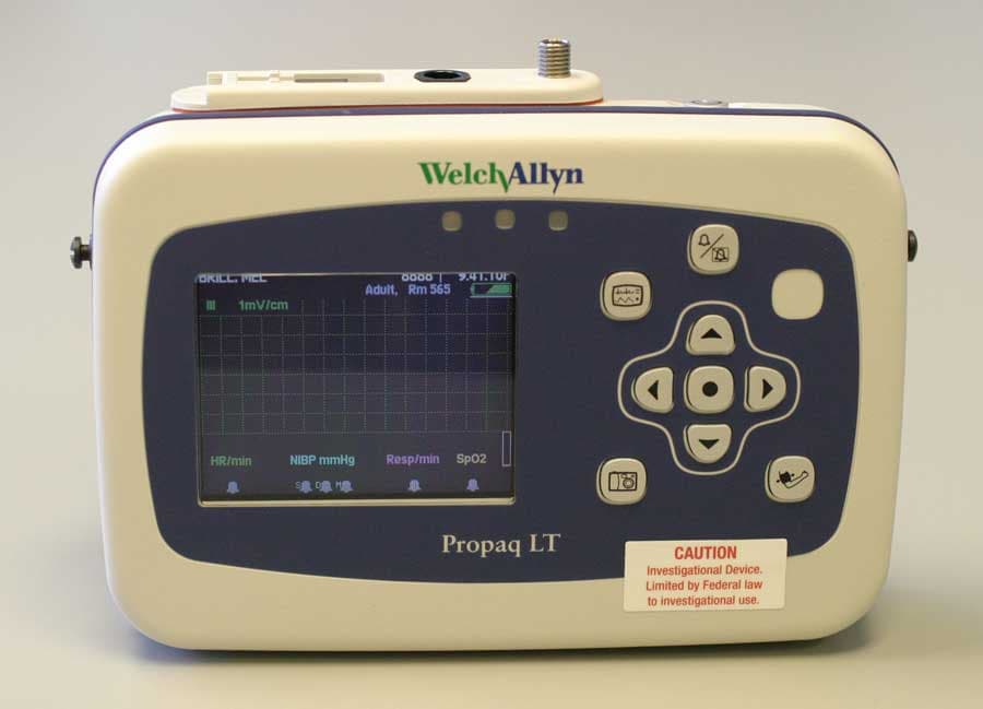
Click to zoom
Application Details
- Equipment Class
- DSS - Part 15 Spread Spectrum Transmitter
- Date of Grant
- Dec 13, 2005
- Application Purpose
- Original Equipment
- Date of Application
- Dec 13, 2005
- Equipment Note
- Propaq 802 LTRN
- Frequency Range
- 2402.00000000 - 2480.00000000
- Company
- Welch Allyn, Inc.
- Country
- United States
Documents & Files
Document Text
Text extracted from the exhibit documents filed with the FCC. Open a document above to read the original.
Users Manual
Propaq ® LT Vital Signs Monitor Directions for Use Software version 1.0X 140/781 4 0 / 7 8 808 0 121 2 979 7 % HALL, ROBERT E.H A L L , R O B E R T E . 34561873 4 5 6 1 8 7 3:00:06P3 : 0 0 : 0 6 P AdultA d u l t Rm 239R m 2 3 9 HR/m in H R / m i n NIBP mmHg (10 2) N I B P m m H g ( 1 0 2 ) @2:4 7P Manual @ 2 : 4 7 P M a n u a l Resp/mi n R e s p / m i n SpO2S p O 2 SpO2S p O 2 2x2 x II 1mV/cm I I 1 m V / c m iiWelch Allyn Propaq LT Vital Signs Monitor 0123 Copyright 2005 Welch Allyn. All rights are reserved. No one is permitted to reproduce or duplicate, in any form, this manual or any part thereof without permission from Welch Allyn. Welch Allyn assumes no responsibility for any injury to anyone, or for any illegal or improper use of the product, that may result from failure to use this product in accordance with the instructions, cautions, warnings, or statement of intended use published in this manual. Welch Allyn ® , Propaq ® , Acuity ® , Smartcuf ® , and Flexible Monitoring ® are registered trademarks of Welch Allyn. FlexNet ™ and ParamSet ™ are trademarks of Welch Allyn. Nellcor ® and Oximax ® are registered trademarks of Nellcor Puritan Bennett. Software in this product is Copyright 2005 Welch Allyn or its vendors. All rights are reserved. The software is protected by United States of America copyright laws and international treaty provisions applicable worldwide. Under such laws, the licensee is entitled to use the copy of the software incorporated with this instrument as intended in the operation of the product in which it is embedded. The software may not be copied, decompiled, reverse-engineered, disassembled or otherwise reduced to human-perceivable form. This is not a sale of the software or any copy of the software; all right, title and ownership of the software remain with Welch Allyn or its vendors. For information about any Welch Allyn product, call the nearest Welch Allyn representative: This device complies with Part 15 of the FCC rules and with the rules of the Canadian ECES-003. Operation is subject to the following two conditions: (1) This device may not cause harmful interference and (2) this device must accept any interference received, including interference that may cause undesired operation. Caution! Changes or modifications not expressly approved by Welch Allyn could void the purchaser’s authority to operate the equipment. Reorder Part Number 810-1828-XX Manual Part Number 810-1702-00 Rev A, November 2005 Welch Allyn 8500 SW Creekside Place Beaverton, Oregon 97008-7107 www.monitoring.welchallyn.com Printed in USA USA 1 800 535 6663 + 1 315 685 4560 Australia + 6129 638 3000 800 074 793 Canada 1 800 561 8797China + 86 216 327 9631 European Call Center + 353 46 906 7790France + 3315 569 5849 Germany + 49 747 792 7186Japan + 8133 219 0071 Latin America + 1 305 669 9003Netherlands + 3115 750 5000 Singapore + 656 419 8100South Africa + 2711 777 7555 United Kingdom + 44 207 365 6780Sweden + 46 85 853 6551 iii Contents 1 - Introduction . . . . . . . . . . . . . . . . . . . . . . . . . . . . . . . . . . . . . . . . . . . . . 1 Intended Use . . . . . . . . . . . . . . . . . . . . . . . . . . . . . . . . . . . . . . . . . . . . . . . . . . . . 1 Symbols . . . . . . . . . . . . . . . . . . . . . . . . . . . . . . . . . . . . . . . . . . . . . . . . . . . . . . . . 2 Safety . . . . . . . . . . . . . . . . . . . . . . . . . . . . . . . . . . . . . . . . . . . . . . . . . . . . . . . . . . 5 General Warnings . . . . . . . . . . . . . . . . . . . . . . . . . . . . . . . . . . . . . . . . . . . . . . 5 General Cautions . . . . . . . . . . . . . . . . . . . . . . . . . . . . . . . . . . . . . . . . . . . . . . 7 Controls, Indicators, and Connectors . . . . . . . . . . . . . . . . . . . . . . . . . . . . . . . . . . 8 Features and Functions. . . . . . . . . . . . . . . . . . . . . . . . . . . . . . . . . . . . . . . . . . . . 10 Models . . . . . . . . . . . . . . . . . . . . . . . . . . . . . . . . . . . . . . . . . . . . . . . . . . . . . . . . 10 Accessories . . . . . . . . . . . . . . . . . . . . . . . . . . . . . . . . . . . . . . . . . . . . . . . . . . . . 11 USB Option. . . . . . . . . . . . . . . . . . . . . . . . . . . . . . . . . . . . . . . . . . . . . . . . . . . . . 11 HIPAA Considerations. . . . . . . . . . . . . . . . . . . . . . . . . . . . . . . . . . . . . . . . . . . . . 12 Monitor. . . . . . . . . . . . . . . . . . . . . . . . . . . . . . . . . . . . . . . . . . . . . . . . . . . . . 12 Configuration Utility . . . . . . . . . . . . . . . . . . . . . . . . . . . . . . . . . . . . . . . . . . . 12 AutoPrint Utility . . . . . . . . . . . . . . . . . . . . . . . . . . . . . . . . . . . . . . . . . . . . . . 12 2 - Overview of Monitor Operation . . . . . . . . . . . . . . . . . . . . . . . . . . . . 13 Turning On the Monitor. . . . . . . . . . . . . . . . . . . . . . . . . . . . . . . . . . . . . . . . . . . . 13 Selecting a Language . . . . . . . . . . . . . . . . . . . . . . . . . . . . . . . . . . . . . . . . . . . . . 15 About the Charging/Communications Cradle . . . . . . . . . . . . . . . . . . . . . . . . . . . 16 About the USB Data Transfer Option . . . . . . . . . . . . . . . . . . . . . . . . . . . . . . 17 Setting Up the Cradle . . . . . . . . . . . . . . . . . . . . . . . . . . . . . . . . . . . . . . . . . . 17 Removing the Monitor from the Cradle . . . . . . . . . . . . . . . . . . . . . . . . . . . . 18 Displaying Data . . . . . . . . . . . . . . . . . . . . . . . . . . . . . . . . . . . . . . . . . . . . . . . . . . 19 About Display Formats . . . . . . . . . . . . . . . . . . . . . . . . . . . . . . . . . . . . . . . . . 21 Timing Out the Display and the Back Light . . . . . . . . . . . . . . . . . . . . . . . . . 23 Locking Out the Display, Back Light, and Buttons . . . . . . . . . . . . . . . . . . . . 23 Large Color Display Interface . . . . . . . . . . . . . . . . . . . . . . . . . . . . . . . . . . . . 24 About Navigation . . . . . . . . . . …
Text truncated - open the document above for the full version.
Users Manual
1 1 Introduction Intended Use. . . . . . . . . . . . . . . . . . . . . . . . . . . . . . . . . . . . . . . . . . . . . . . . . . . . .1 Symbols. . . . . . . . . . . . . . . . . . . . . . . . . . . . . . . . . . . . . . . . . . . . . . . . . . . . . . . . .2 Safety. . . . . . . . . . . . . . . . . . . . . . . . . . . . . . . . . . . . . . . . . . . . . . . . . . . . . . . . . . .5 Controls, Indicators, and Connectors . . . . . . . . . . . . . . . . . . . . . . . . . . . . . . . . . .8 Features and Functions . . . . . . . . . . . . . . . . . . . . . . . . . . . . . . . . . . . . . . . . . . . . 10 Models. . . . . . . . . . . . . . . . . . . . . . . . . . . . . . . . . . . . . . . . . . . . . . . . . . . . . . . . . 10 Accessories. . . . . . . . . . . . . . . . . . . . . . . . . . . . . . . . . . . . . . . . . . . . . . . . . . . . . 11 USB Option . . . . . . . . . . . . . . . . . . . . . . . . . . . . . . . . . . . . . . . . . . . . . . . . . . . . . 11 HIPAA Considerations . . . . . . . . . . . . . . . . . . . . . . . . . . . . . . . . . . . . . . . . . . . . . 12 Intended Use The Propaq LT Series (802LT0N and 802LTRN) monitors are portable devices intended to be used by clinicians and medically qualified personnel for single or multiparameter vital-signs monitoring of ambulatory and nonambulatory neonate, pediatric and adult patients. These devices are indicated for ECG, noninvasive blood pressure (NIBP), respiration and SpO 2 . The most likely locations for patients to be monitored by these devices are hospital general medical-surgical, telemetry, and intermediate care floors, hospital emergency departments, transport, emergency medical services, and other healthcare applications. The monitors can be used as standalone devices or as devices networked to an Acuity Central Station (referred to in this manual as ‘Acuity’) through wireless communication over a Welch Allyn FlexNet network. Federal USA law restricts this device to sale, distribution, or use by or on the order of a licensed healthcare professional. Even though this manual describes some monitoring techniques, the monitor is intended for use only by trained and experienced clinicians who know how to measure and interpret vital signs. 2IntroductionWelch Allyn Propaq LT Vital Signs Monitor Symbols Table 1. Directions for Use WARNINGIndicates conditions that could lead to illness, injury, or death. CautionIn this manual, indicates conditions that could damage equipment or other property. CautionOn the product, means “Consult the accompanying documentation.” Table 2. Control Buttons Monitor Power - Turn the monitor power on or off.Down - Move the cursor down to the next display item. Action - Act based on what is highlighted. (See “Using the Action Button” on page 32.) Silence/Reset - Silence the current alarm tone for 90 seconds or reset a silenced alarm tone. Left - Move the cursor left to the next display item; decrease the parameter value. Display - Cycle to the next configured display format, or cancel the current control, setup, or pop-up menu. Right - Move the cursor right to the next display item; increase the parameter value. Snapshot - Record a 21 -second period of numeric and waveform data. Up - Move the cursor up to the next display item. Start/Stop NIBP - Start or stop an NIBP measurement. Cradle Monitor Release - Press and then hold while removing the monitor from the cradle. Table 3. Status Indicators Monitor (green) Monitoring normally (no active alarms or alerts). Connection to Acuity is confirmed and patient identification is confirmed. (Wireless only, Acuity enabled.) (green flashing) Monitoring normally (no active alarms or alerts). (Standalone only.) Patient confirmed, and monitor then intentionally disconnected. (Wireless only, Acuity enabled.) (yellow) At least one alarm is disabled. Monitor disconnected, connecting or connected; patient not confirmed. (Wireless only, Acuity enabled.) (yellow flashing) Equipment alert. Acuity message windows. (Wireless only, Acuity enabled.) (red flashing) Patient alarm. Directions for UseIntroduction3 Upper and lower alarm limits for this parameter are on. The upper alarm limit for this parameter is on and the lower is off. The upper alarm limit for this parameter is off and the lower is on. Upper and lower alarm limits for this parameter are off. A snapshot exists for this period. The snapshot for this period has been replaced with a more recent snapshot. (green) The battery is fully charged. The battery is partially full. The battery is partially full and is charging. (yellow) The battery is low. The battery is low and is charging. (red)The battery is near failure; the monitor will shut down soon. If this indicator appears while the monitor is in the cradle, the battery cannot be charged and must be replaced. The battery is near failure and is charging. The monitor will shut down if removed from the cradle. The monitor is communicating wirelessly with the network and with Acuity. (Wireless only, Acuity enabled.) The monitor is not communicating with the wireless network. (Wireless only, Acuity enabled.) (Flashing) The monitor is communicating with the network but is not communicating with Acuity. (Wireless only, Acuity enabled.) The monitor is communicating by USB cable with a PC. Cradle (green) Cradle is powered. (green) Monitor battery is charging. NOTE: When the battery is fully charged, this indicator is not lit. (yellow) Cradle fault or battery fault, or the monitor is not properly seated in the cradle. Table 3. Status Indicators (continued) 4IntroductionWelch Allyn Propaq LT Vital Signs Monitor Table 4. Labels Monitor Proceed with caution. If in doubt, refer to the accompanying documentation. Enclosure protection: Drip -proof. Class IPX1 per EN60529:1991. The monitor or accessory meets all essential requirements of the European Medical Device Directive 93/42/EEC for a Class II-b product. The monitor is certified by the Canadian Standards Association International to …
Text truncated - open the document above for the full version.
Users Manual
2 13 Overview of Monitor Operation Turning On the Monitor. . . . . . . . . . . . . . . . . . . . . . . . . . . . . . . . . . . . . . . . . . . . 13 Selecting a Language . . . . . . . . . . . . . . . . . . . . . . . . . . . . . . . . . . . . . . . . . . . . . 15 About the Charging/Communications Cradle . . . . . . . . . . . . . . . . . . . . . . . . . . . 16 Displaying Data . . . . . . . . . . . . . . . . . . . . . . . . . . . . . . . . . . . . . . . . . . . . . . . . . . 19 About Navigation. . . . . . . . . . . . . . . . . . . . . . . . . . . . . . . . . . . . . . . . . . . . . . . . .32 Menus. . . . . . . . . . . . . . . . . . . . . . . . . . . . . . . . . . . . . . . . . . . . . . . . . . . . . . . . .34 About Monitor Information Screens . . . . . . . . . . . . . . . . . . . . . . . . . . . . . . . . . .39 Using Demo Mode . . . . . . . . . . . . . . . . . . . . . . . . . . . . . . . . . . . . . . . . . . . . . . .41 Power Saving. . . . . . . . . . . . . . . . . . . . . . . . . . . . . . . . . . . . . . . . . . . . . . . . . . . .45 Turning Off the Monitor. . . . . . . . . . . . . . . . . . . . . . . . . . . . . . . . . . . . . . . . . . . .45 Communicating with an Acuity Central Station. . . . . . . . . . . . . . . . . . . . . . . . . .45 About Error Detection . . . . . . . . . . . . . . . . . . . . . . . . . . . . . . . . . . . . . . . . . . . . .45 Transporting the Monitor with the Patient. . . . . . . . . . . . . . . . . . . . . . . . . . . . . .46 Turning On the Monitor To Turn On the Monitor Press and hold until a tone sounds. 1. A tone sounds as the green, yellow, and red lights turn on and off. This occurs twice. 2. The splash screen appears (Figure 6), identifying the product and displaying the message “Diagnostics in progress”. The green light turns on and off quickly while the low tone sounds, the yellow light turns on and off quickly while the medium tone sounds, and the red light turns on and off quickly while the loud tone sounds. Note The monitor runs through an operational self-test each time it is powered up. Always verify that it follows this power-up sequence. If it does not, remove it from service and have it examined by a qualified service person. Note When step 2 completes as described, the monitor has verified that the visual and audible alarm indicators are working properly. 14Overview of Monitor OperationWelch Allyn Propaq LT Vital Signs Monitor Figure 6. Splash Screen 3. The splash screen is replaced by a power-on screen (Figure 7): Figure 7. Power-Up Screens To start monitoring from this point, see “Standalone Monitoring” on page 49. To practice using the monitor, see “Using Demo Mode” on page 41. Application Version 1.00.00Application Version 1.00.00 Bootcore Version 1.00.00Bootcore Version 1.00.00 PropaqPropaq ® LT LT Diagnostics in progressDiagnostics in progress Welch Allyn 2005Welch Allyn 2005 c Select ( ) to Start a New Patient.Select ( ) to Start a New Patient. No data saved.No data saved. Start New PatientStart New Patient InfoInfo DemoDemo Portland Westside HospitalPortland Westside Hospital Emergency DepartmentEmergency Department Select ( ) to delete dataSelect ( ) to delete data and start a new patient.and start a new patient. Portland Westside HospitalPortland Westside Hospital Emergency DepartmentEmergency Department Note!Note! There is patient data stored forThere is patient data stored for Hall, Robert E. ID: 3456187Hall, Robert E. ID: 3456187 Start New PatientStart New PatientContinue PatientContinue PatientInfoInfoDemoDemo Directions for UseOverview of Monitor Operation15 Selecting a Language To change the language of the monitor interface: 1. If the monitor power is on, press to turn it off. 2. Press to turn the monitor power on. 3. Immediately after pressing , and before any screen appears, simultaneously press the up arrow and down arrow buttons ( and ). Keep the buttons pressed until the language selection screen appears (Figure 8). Figure 8. Language Selection Screen 4. Use the arrow buttons (, , , and ) to highlight the language you wish to use. 5. Press. The monitor powers down and then powers up in the selected language. The monitor will always power up in this language until the setting is changed again. You can change the setting again only by one of the following: •Performing this procedure again. •Downloading a new configuration to the monitor. (See “Configuring the Monitor” on page 126). •Acuity. Note If you select French, HR/PR alarm limits cannot be turned off unless you go through the service menus to change this setting. If you do change this setting, the change stays in effect through power cycles. For information about using the service menus, refer to the Propaq LT Monitor Service Manual (810-1811-XX). EnglishEnglish DeutschDeutsch Franç.Franç. EspañolEspañol Ital.Ital. PolskiPolski NederlNederl SvenskaSvenska PortuguêsPortuguês 16Overview of Monitor OperationWelch Allyn Propaq LT Vital Signs Monitor About the Charging/Communications Cradle When the Charging/Communication Cradle (the cradle) is attached to AC (or to vehicle DC) power and the monitor is seated in the cradle (Figure 9), the cradle does the following: •Recharges the monitor battery, whether patient monitoring is occurring or not. •Powers the monitor, conserving the charge on the monitor battery. •(If the cradle has the USB data transfer option) enables data transfer between a PC and a monitor . See “About the USB Data Transfer Option” on page 17. The cradle is intended to hold the monitor when the patient is in bed or is otherwise stationary. The cradle can sit on a flat surface near the patient, attach to the bed rail (using the bed-rail hook), or hang from an IV pole (using the optional IV Pole Mount accessory). If the monitor is in the cradle and the AC power adapter is connected to the cradle, the monitor runs on AC power rather than battery power. This keeps the monitor battery at full charge so that it can then run under battery power when it is removed…
Text truncated - open the document above for the full version.
Users Manual
Directions for UseOverview of Monitor Operation29 Assembling the Large Color Display Refer to Figure 22, Figure 23 on page 30, or Figure 24 on page 31. Figure 22. Mounting the Interface Box (with Face Plate) on the Large Display Mounting Bracket 60-mm screws 620-0431-00 40-mm screws 620-0432-00 Long cables between box and cradle: 008-0946-00 (USB) 008-0948-00 (Power) 30Overview of Monitor OperationWelch Allyn Propaq LT Vital Signs Monitor Figure 23. Mounting the Interface Box on the Cradle 40-mm screws 620-0432-00 18-mm screws 620-0433-00 Short cables between box and cradle: 008-0947-00 (USB) 008-0949-00 (AC Power) Directions for UseOverview of Monitor Operation31 Figure 24. Mounting the Interface Box and the Cradle on the Large Display Mounting Bracket 40-mm screws 620-0432-00 60-mm screws 620-0431-00 Short cables between box and cradle: 008-0947-00 (USB) 008-0949-00 (AC Power) 32Overview of Monitor OperationWelch Allyn Propaq LT Vital Signs Monitor About Navigation You navigate the monitor screens using , , and (arrow buttons), (action button), and (display button). Using the Arrow Buttons Use , , and to do the following: •Highlight an item on the display. (See “Using the Highlights” on page 33.) •Select options from a control menu. •Use and to select options from a pop-up menu. •Use and to change the values of numeric parameters. Using the Action Button Use to do the following: •Display the control menu for a blue-highlighted item. •Return from a control menu to the primary display. •Access the Setup menu when Setup is highlighted. •Display tabular and graphical trends when Trends is highlighted. •Display snapshots when Snapshot is highlighted. •Turn on the display or the back light if either has been turned off by a time-out. •Display a pop-up menu. Using the Display Button Use to do the following: •Cycle through the configured display formats. •Return from a control menu to the primary display. •Close a pop-up menu. Directions for UseOverview of Monitor Operation33 Using the Highlights Every screen contains a single element—the current context—highlighted by a blue field. Some screens also contain elements—parameter values—highlighted by a green field. About Blue Highlights A blue highlight identifies the current context. For example, Figure 25 illustrates a highlighted row in a trends display and a highlighted setting in the Waveform Size menu. Figure 25. Examples of Highlighted Elements In a display screen (see “About Display Formats” on page 21), pressing causes the monitor to replace the current screen with another screen related to the current context. For example, if SpO 2 is highlighted in the Two Waveforms display (Figure 26) and you press... Figure 26. Using the Action Button () ...the monitor presents the SpO 2 control menu (Figure 27). About Green Highlights Green highlights identify the current values of multiple parameters within a given context. For example, in the control menu shown in Figure 27, the current settings of the SpO 2 parameters are highlighted in green. II 1mV/cmII 1mV/cm % 12:4112:41 12:4012:40 12:3912:39 12:3812:38 12:3712:37 12:3812:38 12:3612:36 125125 122122 100100 7575 5050 2525 130/65 (93)130/65 (93) 112/87 (87)112/87 (87) 192/110 (130)192/110 (130) n/an/a n/an/a n/an/a n/an/a 2222 1818 1616 1717 1919 1919 9898 9898 9999 9999 9898 100100 n/an/a 1212 SpO2SpO2 SEARCHSEARCHTabularTabular TimeTime 8080140/78140/78 HR/minHR/minNIBP mmHgNIBP mmHgResp/minResp/min n/an/a HALL, ROBERT E.HALL, ROBERT E.3456187345618712:41:3212:41:32 AdultAdultRm 239Rm 239 Waveform SizeWaveform Size 0.2 mV/cm0.2 mV/cm 0.5 mV/cm0.5 mV/cm 1 mV/cm1 mV/cm 2 mV/cm2 mV/cm 4 mV/cm4 mV/cm 8 mV/cm8 mV/cm Highlights Drop-down menu Vital-signs display 140/78140/78 8080 1212 9797 % HALL, ROBERT E.HALL, ROBERT E.345618734561873:00:06P3:00:06P AdultAdultRm 239Rm 239 HR/minHR/minNIBP mmHg (102)NIBP mmHg (102) @2:47P Manual@2:47P Manual Resp/minResp/minSpO2SpO2 SpO2SpO22x2x II 1mV/cmII 1mV/cm With SpO 2 highlighted, press (Two Waveforms display) 34Overview of Monitor OperationWelch Allyn Propaq LT Vital Signs Monitor Menus Using Control Menus Figure 27. SpO 2 Control Menu (Example) A control menu includes a topic name for the current context (for example, SpO 2 ); a column of parameters with one highlighted (for example, SpO 2 Monitoring); and a column of options, with one item in each set of options highlighted (for example, Standby, On, 100, On, 90, Low). The blue highlight indicates the parameter currently enabled for modification. The green highlights indicate the current settings for all parameters in the menu. At the bottom of the screen for all control menus are links to Exit, Trends, Snapshots, and Setup. ExitReturn to the vital-signs display. TrendsView a tabular history. Snapshots View a series of 21-second waveform snapshots of the current patient’s vital signs. SetupAccess the setup menu. (See “To Access the Setup Menus” on page 38.) % HALL, ROBERT E.HALL, ROBERT E.345618734561873:00:06P3:00:06P AdultAdultRm 239Rm 239 II 1mV/cmII 1mV/cm ExitExitTrendsTrendsSnapshotsSnapshotsSetupSetup SpO2 MonitoringSpO2 Monitoring Upper AlarmUpper Alarm Upper LimitUpper Limit Lower AlarmLower Alarm Lower LimitLower Limit HP/PR ToneHP/PR Tone SpO2SpO2 OffOff OffOff OffOff OffOff OnOn OnOn OnOn LowLowMedMedHighHigh 100100 9090 StandbyStandby 8080 HR/minHR/min 140/78140/78 NIBP mmHg (102)NIBP mmHg (102)Resp/minResp/minSpO2SpO2 12129797 Control menu Control context Parameters Current settings Directions for UseOverview of Monitor Operation35 Example: Using a Control Menu Using the example (Figure 27), you would do the following to raise the SpO 2 lower alarm limit to 95 (Step 1) and shut off the HR/PR tone (Step 2): 1.W i t h SpO 2 Monitoring highlighted, scroll (using ) to highlight Lower Limit, and press as many times as needed to raise this alarm limit to 95. 2. Scroll (using ) to HR/PR Tone, and press either or as many times as needed to highlight Off. 3. Press or to exit the control screen and …
Text truncated - open the document above for the full version.
Users Manual
3 49 Standalone Monitoring Overview. . . . . . . . . . . . . . . . . . . . . . . . . . . . . . . . . . . . . . . . . . . . . . . . . . . . . . .49 Preparing for a New Patient. . . . . . . . . . . . . . . . . . . . . . . . . . . . . . . . . . . . . . . . .50 Continuing to Monitor a Patient on Power-Up . . . . . . . . . . . . . . . . . . . . . . . . . . .54 Monitoring ECG and Resp. . . . . . . . . . . . . . . . . . . . . . . . . . . . . . . . . . . . . . . . . .55 Monitoring SpO2. . . . . . . . . . . . . . . . . . . . . . . . . . . . . . . . . . . . . . . . . . . . . . . . .64 Monitoring Blood Pressure (NIBP). . . . . . . . . . . . . . . . . . . . . . . . . . . . . . . . . . . .69 To Discontinue Monitoring. . . . . . . . . . . . . . . . . . . . . . . . . . . . . . . . . . . . . . . . . .75 Overview The monitor is available as a standalone (model 802LT0N) or wireless model (model 802LTRN). This chapter describes the operation of the standalone monitor, and of the wireless monitor when it is not in communication with the Welch Allyn Flexnet ® network and an Acuity ® Central Station. About the Model 802LT0N (Standalone) Monitor The model 802LT0N monitor operates in standalone mode. It measures and displays vital signs, stores patient data, and locally indicates alarms and alert conditions. •The configuration of the monitor is not affected by Acuity. •The vital signs stored by the monitor are not sent to Acuity. •Alarms and alerts generated by the monitor do not appear on Acuity. •Alarms and alerts generated by Acuity do not appear on the monitor. •Acuity does not update the monitor time and date settings. About the Model 802LTRN (Wireless) Monitor See “Monitoring in Communication with Acuity” on page 77. 50Standalone MonitoringWelch Allyn Propaq LT Vital Signs Monitor Preparing for a New Patient To Begin Monitoring a New Patient 1.If the monitor is on, press to turn it off. If prompted to save or delete existing data, highlight Delete and press . The monitor deletes any saved data and temporary settings, and then shuts down. 2. Press to turn on the monitor. •If the monitor holds stored data from the previously monitored patient, it displays the “data saved” start-up screen (Figure 43, left): Figure 43. Start-Up with Saved Data •If the data from the previously monitored patient was deleted on shut-down, the “no data saved” start-up screen appears (Figure 44): Figure 44. Start-Up with No Saved Data 3. Highlight Start New Patient and press. The first configured data display appears (Figure 45). In place of a patient name, ID: is followed by a string that is generated by the monitor when you select ‘Start New Patient’. This AutoID string, a combination of serial number, time, and date, is unique to each new patient, and identifies the patient until you supply the patient identification data. Select ( ) to delete dataSelect ( ) to delete data and start a new patient.and start a new patient. Portland Westside HospitalPortland Westside Hospital Emergency DepartmentEmergency Department Note!Note! There is patient data stored forThere is patient data stored for Hall, Robert E. ID: 3456187Hall, Robert E. ID: 3456187 Start New PatientStart New PatientContinue PatientContinue PatientInfoInfoDemoDemo Select ( ) to Start a New Patient.Select ( ) to Start a New Patient. No data saved.No data saved. Start New PatientStart New Patient InfoInfo DemoDemo Portland Westside HospitalPortland Westside Hospital Emergency DepartmentEmergency Department Directions for UseStandalone Monitoring51 Figure 45. Data Display with AutoID 4. In the primary data display, highlight ID: (upper left) and press. The Patient Information Entry screen appears (Figure 46): Figure 46. Patient Information Entry 5. Enter the ID and name of the new patient. a. Press or to highlight (blue) a character in the character field (Figure 47). b. Press to copy it to the green-highlighted location in the entry fields (Figure 46). c. Repeat from step a until all characters are entered into the field. d. Press until the insertion point in the entry field changes from green to blue. e. Press or to move the insertion point to another entry field. f.Press to return to the character field. g. Repeat from step a until all fields are complete. Figure 47. Patient Information Entry (continued) Note To correct an error in an entry field: Place the cursor (step d and step e) to the right of the error location, highlight and enter Backspace in the character field to delete the erroneous character, and then enter the correct character. ID: 0101819RO17QID: 0101819RO17Q8:82:568:82:56 AdultAdultRmRm NIBP mmHgNIBP mmHgResp/minResp/min HR/minHR/minSpO2SpO2 % SDM Start-up AutoID LastLastMiddleMiddleFirstFirstID#ID#Rm#Rm# ABCDEFGHIJKLMNOPQRSTUV WXYZ1234567890- Select ( ) to enter highlighted characterSelect ( ) to enter highlighted character ConfirmConfirmCancelCancel BackspaceBackspace Entry fields Character field LastLastMiddleMiddleFirstFirstID#ID#Rm#Rm# ABCDEFGHIJKLMNOPQRSTUV WXYZ1234567890- Select ( ) to enter highlighted characterSelect ( ) to enter highlighted character ConfirmConfirmCancelCancel HALLHALLERORO BackspaceBackspace 34561873456187 Next letter highlighted 52Standalone MonitoringWelch Allyn Propaq LT Vital Signs Monitor 6. Highlight Confirm and press. \ 7.Verify that the patient mode (adult, pediatric, or neonate) is set correctly for this patient. NeonatalTerm birth through 28 days, or up to 44 gestational weeks. PediatricBetween 29 days and 12 years. Adult13 years and older. If the current patient mode setting is not correct: a. Highlight the current patient mode (Adult, Pediatric, or Neonate) and press. b. From the Patient Mode selection menu (Figure 48), highlight the appropriate patient mode and press. Figure 48. Changing Patient Mode c. A confirmation screen appears: Figure 49. Confirming a Change of Patient Mode d. To confirm the change, highlight Confirm and press. Note Name alone is not sufficient to confirm a patient ID; thus, you can confir…
Text truncated - open the document above for the full version.
Contact Information
Applicant
Robert Berry(Regulatory Affairs Manager)
Test Firm
Northwest EMC, Inc.Greg Kiemel
Technical Specifications
| # | Rule Parts | Frequency Range | Power Output |
|---|---|---|---|
| 1 | 15C | 2.40 GHz - 2.48 GHz | 109.70 mW |
Other Applications from Welch Allyn, Inc.

PGUVS100
Jan 25, 2015WATY
Equipment Class
DTS - Digital Transmission System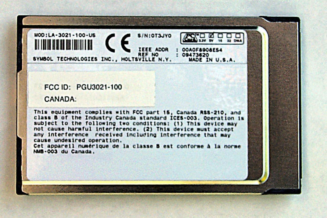
PGU3021-100
Oct 15, 2001Propaq G Series Wireless Option
Equipment Class
DSS - Part 15 Spread Spectrum Transmitter