PGUVS100WATY
Welch Allyn, Inc.
Click to zoom
Application Details
- Equipment Class
- DTS - Digital Transmission System
- Date of Grant
- Jan 25, 2015
- Application Purpose
- Original Equipment
- Date of Application
- Jan 25, 2015
- Equipment Note
- WATY
- Frequency Range
- 2412.00000000 - 2462.00000000
- Company
- Welch Allyn, Inc.
- Country
- United States
Documents & Files
Document Text
Text extracted from the exhibit documents filed with the FCC. Open a document above to read the original.
Users Manual
DRA F T Welch Allyn ® Spot ® Vision Screener Model VS100 Directions for use iiWelch Allyn Spot Vision Screener VS100 DRA F T © 2015 Welch Allyn. All rights are reserved. To support the intended use of the product described in this publication, the purchaser of the product is permitted to copy this publication, for internal distribution only, from the media provided by Welch Allyn. No other use, reproduction, or distribution of the publication, or any part of it, is permitted without written permission from Welch Allyn. Welch Allyn assumes no responsibility for any injury to anyone, or for any illegal or improper use of the product, that may result from failure to use this product in accordance with the instructions, cautions, warnings, or statement of intended use published in this manual. Welch Allyn ® and Spot ® are registered trademarks of Welch Allyn. Software in this product is Copyright 2014 Welch Allyn or its vendors. All rights are reserved. The software is protected by United States of America copyright laws and international treaty provisions applicable worldwide. Under such laws, the licensee is entitled to use the copy of the software incorporated with this instrument as intended in the operation of the product in which it is embedded. The software may not be copied, decompiled, reverse-engineered, disassembled, or otherwise reduced to human-perceivable form. This is not a sale of the software or any copy of the software; all right, title, and ownership of the software remain with Welch Allyn or its vendors. This product may contain "free" or "open source" software (FOSS). To learn more about Welch Allyn's use and support of FOSS, please visit http://www.welchallyn.com/opensource. For patent information, please visit www.welchallyn.com/patents. For information about any Welch Allyn product, contact Welch Allyn Technical Support: www.welchallyn.com/about/company/locations.htm. Manual Material No. 722911 Ver A DIR 80019921 Revision date: 2015-01 Welch Allyn, Inc. 4341 State Street Road Skaneateles Falls, NY 13153 USA This manual applies to 901029 Vision Screener. Regulatory Affairs Representative Welch Allyn Limited Navan Business Park Dublin Road Navan, County Meath, Republic of Ireland 1 1 DRA F T Introduction This Directions for use manual is a comprehensive guide designed to help you understand the capabilities and operation of your Spot Vision Screener VS100. The information in this manual includes all options available with the Spot Vision Screener. The applicability of some sections of this manual depends on the configuration of your particular device. Read this manual thoroughly before attempting to use the device. The vision screener is a hand-held instrument with a video display on the rear of the unit that provides subject visualization and alignment. Video display also provides user interface functionality for data input and display. The vision screener provides visual and audible cues to attract subject’s attention and gaze. The device provides a fast data collect for easy evaluation of the most difficult pediatric subjects of limited compliance. Each evaluation provides simultaneous binocular assessment of the subject’s refraction, pupil size and gaze. Intended use The Spot Vision screener is intended to measure the refractive power of the eye by measuring light reflexes from the retina. It also estimates pupil size, pupil distance and eye gaze deviation. It is intended for use on subjects six months of age through adults. Indications for use The Spot Vision screener is indicated for use by healthcare professionals or under the direction of a healthcare professional to screen or evaluate individuals for potential refractive errors associated with poor vision. Contraindications The Spot Vision Screener has no known contraindications. 2IntroductionWelch Allyn Spot Vision Screener VS100 DRA F T Symbols Documentation symbols Power symbols Miscellaneous symbols Consult operating instructions/directions for use (DFU). A copy of the DFU is available on this website. A printed copy of the DFU can be ordered from Welch Allyn for delivery within 7 calendar days. WARNING The warning statements in this manual identify conditions or practices that could lead to loss of data, illness, injury, or death. CAUTION The caution statements in this manual identify conditions or practices that could result in damage to the equipment or other property. Rated power input, DC Battery inside (Not user replaceable) Power On/Off USB port DC power input port, Center pin positive IPXØ Equipment is not protected against the ingress of liquid Non-ionizing electromagnetic radiation This symbol is applicable for EC member countries only. To avoid potential negative consequences for the environment and possibly human health, this instrument should be disposed of (i) for EU member countries - in accordance with WEEE (Directive on Waste Electrical and Electronic Equipment) or (ii) for all other countries, in accordance with local disposal and recycling laws. Directions for useIntroduction3 DRA F T User Interface Symbols The CE mark on this product indicates that it has been tested to and conforms with the provisions noted within the 93/42/ EEC Medical Device Directive. Battery status/level indicator Battery charging (Flashing) or charged (Continuous) Wireless On/Off button Connected to the wireless network No wireless network in range No IP address assigned by the router Unknown network IP ? 4IntroductionWelch Allyn Spot Vision Screener VS100 DRA F T Cannot connect to configured network Sound off Sound on Continue Back Exit Print job in progress ! Directions for useIntroduction5 DRA F T Warnings and cautions WARNING The warning statements in this manual identify conditions or practices that could lead to loss of data, illness, injury, or death. CAUTION The caution statements in this manual identify conditions or practices that could result in damage to the equipment or other property. WARNING Risk of …
Text truncated - open the document above for the full version.
Cover Letter(s)
FCC Compliance Opinion 2015-1-14 PROT0338 Information about the Applicant Grantee (Company Name) Welch Allyn, Inc. FCC Contact Person Kevin Crossen Address 4341 State Street Road City, State, Zip Skaneateles Falls, NY 13153 Job Number PROT0338 Model Bluetooth + Wireless LAN Module FCC ID PGUVS100 Agent Robert Berry Approval Type Original Equipment Class DTS Digital Transmission System Rule Part 15.247 Overview Welch Allyn, Inc is seeking a full modular approval of their 802.11b/g/n radio, model WATY under FCC ID PGUVS100. The radio supports Bluetooth 3.0 + HS and FM receiving but these features are not implemented for this application. The module will only be installed in Welch Allyn products. Confidentiality requested for allowed files. Request is properly addressed and referenced. A letter listing the applicable modular requirements was submitted. Recommendation All items have been resolved and completed to my satisfaction; therefore I recommend this application for approval. Signature Dave Tolman, TCB Committee 1/23/2015
ID Label/Location Info
DESCRIPTIONPART NO. TITLE: AW, WI-FI MODULE LABEL DRAWING NO: 30047736 SHEET 1 OF 1 DATE: 2015-01-07 20142WI-FI MODULE LABEL DRW BY: S.Craig SCALE : 1:1 VERCHANGE NUMBER/APVDDESCRIPTION OF CHANGE ARELEASE TO PRODUCTIOND* BCHANGED MODEL NAME TO WATYD* D* SEE SAP DIR FOR CHANGE NUMBER, APPROVER NAME AND DATE OF APPROVAL Notes: 1. Size: approximately 3/8 in. x 3/8 in. 2. Materials: Non-conductive, appropriate for static sensitive electronic assemblies. 3. Adhesive: Peel and stick type, long term adhesion. SCALE: 1 to 1 SCALE: 4 to 1 .389.65 .389.65 Model: WATY FCC ID: PGUVS100 IC: 4168A-VS100 Model: WATY FCC ID: PGUVS100 IC: 4168A-VS100
ID Label/Location Info
DESCRIPTIONPART NO. TITLE: AW, LBL, VS100, RADIO DRAWING NO: 30047646 SHEET 1 OF 1 DATE: 2014-11-13 DRW BY: C.BAUM SCALE : 1:1 VERCHANGE NUMBER/APVDDESCRIPTION OF CHANGE ARELEASE TO PRODUCTIOND* D* SEE SAP DIR FOR CHANGE NUMBER, APPROVER NAME AND DATE OF APPROVAL 20168BOTTOM LABEL VS100 (CR) NOTES 1. LABEL TEXT AND SYMBOLS CAN BE BLACK ON WHITE BACKGROUND OR WHITE ON BLACK BACKGROUND. 1.5" 1" 802.11a/b/g CONTAINS: FCC ID: PGUVS100 IC: 4168A-VS100 20168 Ver A 802.11a/b/g CONTAINS: FCC ID: PGUVS100 IC: 4168A-VS100 20168 Ver A
Operational Description
W1049B Datasheet version 1.1 2/2008. Antennas with I-PEX Cable Assembly © 2008. All Rights Reserved. Wireless External Antenna for 2.4 GHz Application Single-Band Antenna with I-PEX Cable Assembly. Pulse Part Number: W1049B Pulse Finland Oy Takatie 6 90440 Kempele, Finland Tel: +358 207 935 500 Fax: +358 207 935 501 www.pulseeng.com/antennas Features - Shortest antennas in product line Omni-directional radiation - For WLAN devices using WiFi (802.11b/g), Bluetooth®, ZigBee™ and other applications in the ISM 2.4GHz band - Omnidirectional radiation pattern provides broad 360° coverage - One-quarter wavelength dipole configuration - Various cable length from 3 to 12 inch (76-305mm) Connector - I-PEX Pansize 20/bag; 500/carton Dimensions: Unless otherwise specified, all tolerances are ± Frequency [GHz] 2.4 2.4 2.4 2.4 2.4 Part Number W1049B030 W1049B050 W1049B070 W1049B090 W1049B120 Max Gain [dBi] 2.0 2.0 2.0 2.0 2.0 Impedance [Ω] 50 50 50 50 50 Mechanical Length (in/mm) 3.25/82.5 3.25/82.5 3.25/82.5 3.25/82.5 3.25/82.5 Cable Length (in/mm) 3/76 5/127 7/178 9/229 12/305 Electrical Specifications @ +25 °C Note: This part number is lead-free and RoHS compliant. No additional suffix or identifier is required. Inches mm 0.10 0.25 W1049B Datasheet version 1.1 2/2008. Antennas with I-PEX Cable Assembly © 2008. All Rights Reserved. Wireless External Antenna for 2.4 GHz Application Single-Band Antenna with I-PEX Cable Assembly. Pulse Part Number: W1049B Pulse Finland Oy Takatie 6 90440 Kempele, Finland Tel: +358 207 935 500 Fax: +358 207 935 501 www.pulseeng.com/antennas Application Notes Omni-directional antennas provide a uniform, donut- shaped, 360° radiation pattern. The omni-directional pat- tern is suitable for point-to-multipoint broadcasting in all directions. This antenna is primarily used for WLAN applications. However, it can also be used for a variety of other applications withing the spec ified frequency range. When used as an access point, the antenna is ideally located at the center of the coverage area. Gain Performance W1049B030 E-PLANE H-PLANE 0 345 330 315 300 285 270 255 240 225 210 195 180 165 150 135 120 105 90 75 60 45 30 15 -30-20-100 dB 2.4GHz 1.61476dBi 0 345 330 315 300 285 270 255 240 225 210 195 180 165 150 135 120 105 90 75 60 45 30 15 -30-20-100 dB 2.45GHz 1.6233dBi 0 345 330 315 300 285 270 255 240 225 210 195 180 165 150 135 120 105 90 75 60 45 30 15 -30-20-100 dB 2.5GHz 1.59034dBi 0 345 330 315 300 285 270 255 240 225 210 195 180 165 150 135 120 105 90 75 60 45 30 15 -30-20-100 dB 2.4GHz 1.55524dBi 0 345 330 315 300 285 270 255 240 225 210 195 180 165 150 135 120 105 90 75 60 45 30 15 -30-20-100 dB 2.45GHz 1.51154dBi 0 345 330 315 300 285 270 255 240 225 210 195 180 165 150 135 120 105 90 75 60 45 30 15 -30-20-100 dB 2.5GHz 1.38176dBi 0 345 330 315 300 285 270 255 240 225 210 195 180 165 150 135 120 105 90 75 60 45 30 15 -30-20-100 dB 2.4GHz 1.61476dBi 0 345 330 315 300 285 270 255 240 225 210 195 180 165 150 135 120 105 90 75 60 45 30 15 -30-20-100 dB 2.45GHz 1.6233dBi 0 345 330 315 300 285 270 255 240 225 210 195 180 165 150 135 120 105 90 75 60 45 30 15 -30-20-100 dB 2.5GHz 1.59034dBi 0 345 330 315 300 285 270 255 240 225 210 195 180 165 150 135 120 105 90 75 60 45 30 15 -30-20-100 dB 2.4GHz 1.55524dBi 0 345 330 315 300 285 270 255 240 225 210 195 180 165 150 135 120 105 90 75 60 45 30 15 -30-20-100 dB 2.45GHz 1.51154dBi 0 345 330 315 300 285 270 255 240 225 210 195 180 165 150 135 120 105 90 75 60 45 30 15 -30-20-100 dB 2.5GHz 1.38176dBi
RF Exposure Info
RF Exposure Evaluation FCC ID: PGUVS100 The radio module is seeking authorization for both mobile use and for a specific portable implementation in the Welch Allyn Spot Vision Screener Model VS100. Compliance with MPE limits and exclusion from SAR testing is described below: Mobile Use - MPE Compliance For mobile use, the radio module will be used greater than 20cm from the user’s head and torso. FCC KDB 447498 D01 v05r02, Section 7.1 "KDB 447498 D01 General RF Exposure Guidance v05r02" provides the procedures, requirements, and authorization policies for mobile and portable devices. Section 7.1 best fits the exposure condition described in this report. Since these mobile devices are categorically excluded from routine evaluation; simple calculations may be used to estimate the power density to demonstrate compliance with 47 CFR 1.1310 requirements. The following estimate shows MPE limits are met for simultaneous transmission at a 20 cm boundary. The exposure level for the radio is evaluated at a 20 cm distance from the radio’s transmitting antenna using the general equation: Where: S = power density (mW/cm2) P = RMS conducted power input to the antenna (mW) G = numeric power gain relative to an isotropic radiator R = distance to the center of the radiation of the antenna ((20 cm = limit for MPE estimates) P*G = EIRP Solving for S, the maximum power density 20 cm from the transmitting antenna is determined. This level is then compared to the applicable limit. 2 **4 * R GP S Antenna Type Antenna Manufacturer Antenna Part No. Transmit Frequency RMS Conducted Output Power Ante nna Ga in Minimum Antenna Cable Loss Power Density @ 20 cm General Population Ex posure Limi t from 1.1310 (MHz)(mW)(dBi)(dB) (mW/cm 2 )(mW/cm 2 ) OmniPulseW1049B246243.5200.0141 Portable Use – SAR Test Exclusion When the radio module is installed in the Welch Allyn Spot Vision Screener Model VS100, it is held in the hand or can be hanging on a lanyard. These usage conditions position the module’s antenna closer than 20cm to the user’s extremity (hand) or torso. FCC KDB 447498 D01 v05r02, Section 4.3.1 “The 1-g and 10-g SAR test exclusion thresholds for 100 MHz to 6 GHz at test separation distances ≤ 50 mm are determined by: [(max. power of channel, including tune-up tolerance, mW)/(min. test separation distance, mm)] · [√f(GHz)] ≤ 3.0 for 1-g SAR and ≤ 7.5 for 10-g extremity SAR, where f(GHz) is the RF channel transmit frequency in GHz Power and distance are rounded to the nearest mW and mm before calculation The result is rounded to one decimal place for comparison 3.0 and 7.5 are referred to as the numeric thresholds in the step 2 below The test exclusions are applicable only when the minimum test separation distance is ≤ 50 mm and for transmission frequencies between 100 MHz and 6 GHz. When the minimum test separation distance is < 5 mm, a distance of 5 mm according to 5) in section 4.1 is applied to determine SAR test exclusion.” The radio module has a maximum RMS conducted output power of 43.5 mW at 2462 MHz (see attached output power). When used in the Welch Allyn Spot Vision Screener Model VS100, the radio module will have a very limited duty cycle. The VS100 is intended to measure the refractive power of the eye by measuring light reflexes from the retina. The VS100 is indicated for use by healthcare professionals or under the direction of a healthcare professional. The radio module transmits images that are saved during the vision exam at a maximum rate of 1 print every 30 seconds. At the slowest data rate of 1 Mbps, the maximum number of packets (162) in a print will take 1.8 seconds to transmit. This results in a maximum duty cycle of 0.06. Hand held (extremity use) The closest spacing of the antenna to the user’s extremity is 8.3mm as the product can be hand held while transmitting (see photos). The table below shows the results of the calculation. The value of 0.49 is well below the exclusion threshold of 7.5 for 10-g extremity SAR, therefore the unit is excluded from SAR evaluation and deemed compliant with FCC RF exposure requirements. Output Power Duty Cycle Test Separation Transmit Frequency Exclusion Threshold Specification for Extremity SAR (mW) (mm) (GHz) (10-g) 43.5 0.06 8.3 2.462 0.49 <=7.5 Hanging on a Lanyard (body worn use) The closest spacing of the antenna to the user’s torso is 45mm when the VS100 is hanging on a lanyard (see photos). The table below shows the results of the calculation. The value of 0.09 is well below the exclusion threshold of 3.0 for 1-g body SAR, therefore the unit is excluded from SAR evaluation and deemed compliant with FCC RF exposure requirements. Output Power Duty Cycle Test Separation Transmit Frequency Exclusion Threshold Specification for Body SAR (mW) (mm) (GHz) (1-g) 43.5 0.06 45 2.462 0.09 <=3.0 Photos 8.3mm Spacing of internal antenna to the outside of the case. 90mm 45mm 45mm 210mm
Test Report
This report must not be used to claim product certification, approval, or endorsement by NVLAP, NIST, or any agency of the federal government of the United States of America. This Report may only be duplicated in its entirety Welch Allyn Protocol, Inc. WATY FCC 15.247:2014 Report # PROT0338 NVLAP Lab Code: 200630-0 CERTIFICATE OF TEST 2014-12-10 Product compliance is the responsibility of the client; therefore, the tests and equipment modes of operation represented in this report were agreed upon by the client, prior to testing. The results of this test pertain only to the sample(s) tested. The specific description is noted in each of the individual sections of the test report supporting this certificate of test. Last Date of Test: December 09, 2014 Welch Allyn Protocol, Inc. Model: WATY Radio Equipment Testing Standards Specification Method FCC 15.247:2014 ANSI C63.10:2009 KDB 558074 V3 Results Method Clause Test Description Applied Results Comments 6.2 AC Powerline Conduced Emissions Yes Pass 6.5, 6.6 Spurious Radiated Emissions Yes Pass 6.7 Spurious Conducted Emissions Yes Pass 6.7 Band Edge Compliance Yes Pass 6.9.1 Occupied Bandwidth Yes Pass 6.10.2 Output Power Yes Pass 6.11.2 Power Spectral Density Yes Pass 7.5 Duty Cycle Yes N/A Characterization of radio operation. Deviations From Test Standards None Approved By: Kyle Holgate, Operations Manager Report No. PROT03382/110 REVISION HISTORY REV 2014.10.14 Revision Number Description Date Page Number 00 None Report No. PROT03383/110 ACCREDITATIONS AND AUTHORIZATIONS REV 2014.10.08 United States FCC - Designated by the FCC as a Telecommunications Certification Body (TCB). Certification chambers, Open Area Test Sites, and conducted measurement facilities are listed with the FCC. A2LA - Accredited by A2LA to ISO / IEC Guide 65 as a product certifier. This allows Northwest EMC to certify transmitters to FCC and IC specifications. NVLAP - Each laboratory is accredited by NVLAP to ISO 17025 Canada IC - Recognized by Industry Canada as a Certification Body (CB). Certification chambers and Open Area Test Sites are filed with IC. European Union European Commission – Validated by the European Commission as a Conformity Assessment Body (CAB) under the EMC directive and as a Notified Body under the R&TTE Directive. Australia/New Zealand ACMA - Recognized by ACMA as a CAB for the acceptance of test data. Korea MSIP / RRA - Recognized by KCC’s RRA as a CAB for the acceptance of test data. Japan VCCI - Associate Member of the VCCI. Conducted and radiated measurement facilities are registered. Taiwan BSMI – Recognized by BSMI as a CAB for the acceptance of test data. NCC - Recognized by NCC as a CAB for the acceptance of test data. Singapore IDA – Recognized by IDA as a CAB for the acceptance of test data. Israel MOC – Recognized by MOC as a CAB for the acceptance of test data. Hong Kong OFTA – Recognized by OFTA as a CAB for the acceptance of test data. Vietnam MIC – Recognized by MIC as a CAB for the acceptance of test data. SCOPE For details on the Scopes of our Accreditations, please visit: http://www.nwemc.com/accreditations/ Report No. PROT03384/110 MEASUREMENT UNCERTAINTY TMU.2014.12.03 Measurement Uncertainty When a measurement is made, the result will be different from the true or theoretically correct value. The difference is the result of tolerances in the measurement system that cannot be completely eliminated. To the extent that technology allows us, it has been our aim to minimize this error. Measurement uncertainty is a statistical expression of measurement error qualified by a probability distribution. A measurement uncertainty estimation has been performed for each test per our internal quality document WP 342. The estimation is used to compare the measured result with its "true" or theoretically correct value. The expanded measurement uncertainty (K=2) for each test is on each data sheet. Our measurement data meets or exceeds the measurement uncertainty requirements of the applicable specification; therefore, the test data can be compared directly to the specification limit to determine compliance. The calculations for estimating measurement uncertainty are based upon ETSI TR 100 028 (or CISPR 16-4-2 as applicable), and are available upon request. The following table represents the Measurement Uncertainty (MU) budgets for each of the tests that may be contained in this report. Test + MU - MU Frequency Accuracy (Hz) 0.0007% -0.0007% Amplitude Accuracy (dB) 1.2 dB -1.2 dB Conducted Power (dB) 0.3 dB -0.3 dB Radiated Power via Substitution (dB) 0.7 dB -0.7 dB Temperature (degrees C) 0.7°C -0.7°C Humidity (% RH) 2.5% RH -2.5% RH Voltage (AC) 1.0% -1.0% Voltage (DC) 0.7% -0.7% Field Strength (dB) 5.2 dB -5.2 dB AC Powerline Conducted Emissions (dB) 2.9 dB -2.9 dB Report No. PROT03385/110 FACILITIES REV 2015.1.05 California Labs OC01-13 41 Tesla Irvine, CA 92618 (949) 861-8918 Minnesota Labs MN01-08, MN10 9349 W Broadway Ave. Brooklyn Park, MN 55445 (612)-638-5136 New York Labs NY01-04 4939 Jordan Rd. Elbridge, NY 13060 (315) 685-0796 Oregon Labs EV01-12 22975 NW Evergreen Pkwy Hillsboro, OR 97124 (503) 844-4066 Texas Labs TX01-09 3801 E Plano Pkwy Plano, TX 75074 (469) 304-5255 Washington Labs NC01-05 19201 120 th Ave NE Bothell, WA 9801 (425)984-6600 NVLAP NVLAP Lab Code: 200676-0 NVLAP Lab Code: 200881-0 NVLAP Lab Code: 200761-0 NVLAP Lab Code: 200630-0 NVLAP Lab Code:201049-0 NVLAP Lab Code: 200629-0 Industry Canada 2834B-1, 2834B-3 2834E-1 N/A 2834D-1, 2834D-2 2834G-1 2834F-1 BSMI SL2-IN-E-1154R SL2-IN-E-1152R N/A SL2-IN-E-1017 SL2-IN-E-1158R SL2-IN-E-1153R VCCI A-0029 A-0109 N/A A-0108 A-0201 A-0110 Report No. PROT03386/110 PRODUCT DESCRIPTION 2014-12-10 Client and Equipment Under Test (EUT) Information Company Name: Welch Allyn Protocol, Inc. Address: 8500 SW Creekside Place City, State, Zip: Beaverton, OR 97008-7107 Test Requested By: Rob Berry Model: WATY First Date of Test: December 03, 2014 Last Date of Test: December 09, 2014 …
Text truncated - open the document above for the full version.
Test Setup Photos
AC POWERLINE CONDUCTED EMISSIONS WTD.2014.10.14 PSA-ESCI 2014.09.10, EmiR5 2014.10.01.1 AC POWERLINE CONDUCTED EMISSIONS WTD.2014.10.14 PSA-ESCI 2014.09.10, EmiR5 2014.10.01.1 AC POWERLINE CONDUCTED EMISSIONS WTD.2014.10.14 PSA-ESCI 2014.09.10, EmiR5 2014.10.01.1 photo SRC 001.JPG SRC 004.JPG Spurious Radiated Emissions PSA-ESCI 2014.09.10 Report No. PROT03382/21 photo SRC 005.JPG SRC 006.JPG Spurious Radiated Emissions PSA-ESCI 2014.09.10 Report No. PROT03383/21 photo SRC 007.JPG Spurious Radiated Emissions PSA-ESCI 2014.09.10 Report No. PROT03384/21 SPURIOUS CONDUCTED EMISSIONS XMit 2014.02.07 NORTHWEST SPURIOUS CONDUCTED EMISSIONS NweTx 2014.07.18.4 EMC EV06 Direct Connect (1).JPG EV06 Direct Connect (2).JPG SPURIOUS CONDUCTED EMISSIONS Report No. PROT03385/21 SPURIOUS CONDUCTED EMISSIONS XMit 2014.02.07 NORTHWEST SPURIOUS CONDUCTED EMISSIONS NweTx 2014.07.18.4 EMC EV06 Direct Connect (3).JPG EV06 Direct Connect (4).JPG SPURIOUS CONDUCTED EMISSIONS Report No. PROT03386/21 SPURIOUS CONDUCTED EMISSIONS XMit 2014.02.07 NORTHWEST SPURIOUS CONDUCTED EMISSIONS NweTx 2014.07.18.4 EMC EV06 Direct Connect (5).JPG EV06 Direct Connect (6).JPG SPURIOUS CONDUCTED EMISSIONS Report No. PROT03387/21 BAND EDGE COMPLIANCE XMit 2014.02.07 NORTHWEST BAND EDGE COMPLIANCE NweTx 2014.07.18.4 EMC EV06 Direct Connect (1).JPG EV06 Direct Connect (2).JPG BAND EDGE COMPLIANCE Report No. PROT03388/21 BAND EDGE COMPLIANCE XMit 2014.02.07 NORTHWEST BAND EDGE COMPLIANCE NweTx 2014.07.18.4 EMC EV06 Direct Connect (3).JPG EV06 Direct Connect (4).JPG BAND EDGE COMPLIANCE Report No. PROT03389/21 BAND EDGE COMPLIANCE XMit 2014.02.07 NORTHWEST BAND EDGE COMPLIANCE NweTx 2014.07.18.4 EMC EV06 Direct Connect (5).JPG EV06 Direct Connect (6).JPG BAND EDGE COMPLIANCE Report No. PROT033810/21 OCCUPIED BANDWIDTH XMit 2014.02.07 NORTHWEST OCCUPIED BANDWIDTH NweTx 2014.07.18.4 EMC EV06 Direct Connect (1).JPG EV06 Direct Connect (2).JPG OCCUPIED BANDWIDTH Report No. PROT033811/21 OCCUPIED BANDWIDTH XMit 2014.02.07 NORTHWEST OCCUPIED BANDWIDTH NweTx 2014.07.18.4 EMC EV06 Direct Connect (3).JPG EV06 Direct Connect (4).JPG OCCUPIED BANDWIDTH Report No. PROT033812/21 OCCUPIED BANDWIDTH XMit 2014.02.07 NORTHWEST OCCUPIED BANDWIDTH NweTx 2014.07.18.4 EMC EV06 Direct Connect (5).JPG EV06 Direct Connect (6).JPG OCCUPIED BANDWIDTH Report No. PROT033813/21 OUTPUT POWER XMit 2014.02.07 NORTHWEST OUTPUT POWER NweTx 2014.07.18.4 EMC EV06 Direct Connect (1).JPG EV06 Direct Connect (2).JPG OUTPUT POWER Report No. PROT033814/21 OUTPUT POWER XMit 2014.02.07 NORTHWEST OUTPUT POWER NweTx 2014.07.18.4 EMC EV06 Direct Connect (3).JPG EV06 Direct Connect (4).JPG OUTPUT POWER Report No. PROT033815/21 OUTPUT POWER XMit 2014.02.07 NORTHWEST OUTPUT POWER NweTx 2014.07.18.4 EMC EV06 Direct Connect (5).JPG EV06 Direct Connect (6).JPG OUTPUT POWER Report No. PROT033816/21 POWER SPECTRAL DENSITY XMit 2014.02.07 NORTHWEST POWER SPECTRAL DENSITY NweTx 2014.07.18.4 EMC EV06 Direct Connect (1).JPG EV06 Direct Connect (2).JPG POWER SPECTRAL DENSITY Report No. PROT033817/21 POWER SPECTRAL DENSITY XMit 2014.02.07 NORTHWEST POWER SPECTRAL DENSITY NweTx 2014.07.18.4 EMC EV06 Direct Connect (3).JPG EV06 Direct Connect (4).JPG POWER SPECTRAL DENSITY Report No. PROT033818/21 POWER SPECTRAL DENSITY XMit 2014.02.07 NORTHWEST POWER SPECTRAL DENSITY NweTx 2014.07.18.4 EMC EV06 Direct Connect (5).JPG EV06 Direct Connect (6).JPG POWER SPECTRAL DENSITY Report No. PROT033819/21
Contact Information
Applicant
Robert Berry(Regulatory Affairs Manager)
Test Firm
Northwest EMC, Inc.Greg Kiemel
Technical Specifications
| # | Rule Parts | Frequency Range | Power Output |
|---|---|---|---|
| 1 | 15C | 2.41 GHz - 2.46 GHz | 61.40 mW |
Other Applications from Welch Allyn, Inc.
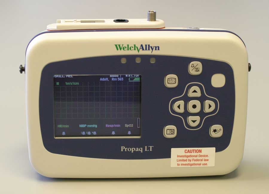
PGUFN802FH
Dec 13, 2005Propaq 802 LTRN
Equipment Class
DSS - Part 15 Spread Spectrum Transmitter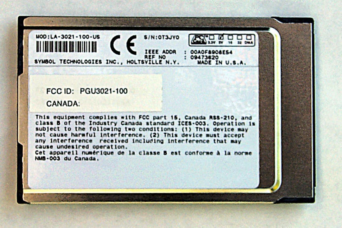
PGU3021-100
Oct 15, 2001Propaq G Series Wireless Option
Equipment Class
DSS - Part 15 Spread Spectrum Transmitter