Text extracted from the exhibit documents filed with the FCC. Open a document above to read the original.
- 1 - OPERATION MANUAL [iDRS-5000] EASTERN INFO-COM INC. http://www.easterninfo.com - 2 - FCC NOTICE THIS DEVICE COMPLIES WITH PART 15 OF THE FCC FULES. OPERATION IS SUBJECT TO THE FOLLOWING TWO CONDITION: (1) THIS DEVICE MAY NOT CAUSE HARMFUL INTERFERENCE, AND (2) THIS DEVICE MUST ACCEPT ANY INTERFERENCE RECEIVED, INCLUDING INTERFERENCE THAT MAY CAUSE UNDERSIRED OPERATION. This equipment has been tested and found to comply with the limits for a Class B digital device, pursuant to part 15 of the FCC Rules. These limits are designed to provide reasonable protection against harmful interference in a residential installation. This equipment generates, uses and can radiate radio frequency energy and, if not installed and used in accordance with the instructions, may cause harmful interference to radio communication. However, there is no guarantee that interference will not occur in a particular installation. If this equipment does cause harmful interference to radio or television reception, which can be determined by turning the equipment off and on, the user is encouraged to try to correct the interference by one or more of the following measures : - Reorient or relocate the receiving antenna. - Increase the separation between the equipment and receiver. - Connect the equipment into an outlet on a circuit difference from that to which the receiver is connected. - Consult the dealer of an experienced radio/TV technician for help. NOTE : The manufacturer is not responsible for any radio or TV interference caused by unauthorized modifications to this equipment. Such modifications could void the user’s authority to operate the equipment. - 3 - 1. iDRS-5000 Board Manual - - 5. Board Minute explanation 4 3 6 5 2 - 4 - - - - - - 5 - iDRS-5000 Digital DIO Pin Configuration 13 25 ο ο ο ο ο ο ο ο ο ο ο ο ο ο ο ο ο ο ο ο ο ο ο ο ο 1 14 Pin # I/O COLOR 1 Sensor 1 BLACK 2 Sensor 2 BROWN 3 Sensor 3 RED 4 Sensor 4 ORANGE 5 Sensor 5 YELLOW 6 Sensor 6 GREEN 7 Sensor 7 BLUE 8 Sensor 8 PURPLE 9 GND BLACK 10 GND BLACK 11 GND BLACK 12 GND BLACK 13 GND BLACK 14 D/O 1 NC WHITE 15 D/O 1 COM GRAY 16 D/O 1 NO BLUE 17 D/O 2 NC WHITE 18 D/O 2 COM GRAY 19 D/O 2 NO YELLOW 20 D/O 3 NC WHITE 21 D/O 3 COM GRAY 22 D/O 3 NO ORANGE 23 D/O 4 NC WHITE 24 D/O 4 COM GRAY 25 D/O 4 NO PURPLE - 6 - 2. Power On 1. To check your camera image, You should turn on cameras, monitor, sensor, etc, before you turn on iDRS-5000. 2. Turn on iDRS-5000. [POWER] lamp will light on, disk check(red LED) blinks then WINDOWS 98 starts. After booting main screen will appear as follows. 3. Main Screen 1) Activated icon will be turned green and show TIP of each icon, when mouse pointer get close to each icon. Inactivated icon will be turned yellow. 2) When consecutive recording, red lamp is displayed in OSD(Camera Name). 3) When motion recording, blue lamp is displayed in OSD(Camera Name). 4) When sensor recording, yellow lamp is displayed in OSD(Camera Name). 5) When [Record] lamp is on and off, it is consecutive recording, [Motion] lamp is on and off, it is motion recording, [Sensor] lamp is on and off, it is sensor recording. 6) Put your mouse pointer to image screen, click left button to enlarge corresponding screen. And click right button to extend to full screen. 7) Click right button in full screen mode to back to main screen. - 7 - Zooming In Zooming Out Focus gets further. 8) [System Shutdown] If you click this icon, confirmation message will appear as follows. If you select [OK] system will be shut down and automatically power OFF. 9) 10) [Motion Tracer] Enlarge a screen in which the motion is detected. 11) [Set up] Change iDRS-3000 set up configurations. (Refer to the ‘2. Set up Change’) 12) [Image search/Playback] Search recorded image. (Refer to the ‘3. See * 3. Image Search) 13) [Camera ON/OFF] Camera ON/OFF icon. When P/T control select camera as 13). If you click this icon power off th4e corresponding camera. 14) Camera Pan/Tilt Control Button. [ - left / - right / - up / - down] 15) [Zoom] Control motorized zoom lens. 16) [Focus] Control camera lens focus. 17) [Light ON/OFF] Control Lighting Equipment. 18) Clock : Indicate present time and date. 19) In case you need to shut down the system by force, push POWER button for 4-5 seconds. But shutting down by force may cause fatal damage to the system itself and data. Please always use [Shut Down] button. Focus gets closer. Quad(4)-screen Rotational All-Channel Display. - 8 - 3. Set up change ( ) 1) [Camera set up] Put each camera name for OSD(On-Screen Display) zone. Set up each camera. If you click system will automatically detect connected camera. [TOTAL BOARD] : Show total number of iDRS-CARDs. [TOTAL SPEED] : Show maximum recording speed. Click to select camera to change camera name iDRS CARD number Input camera number - 9 - 2) [Schedule] Set up each group. Total 10 groups are available (programmable) Select group. Set the days of the week. Connect cameras, motion detectors(software sensor), (external) sensor and D/O. If you want to record specific time, please designate [START TIME], [END TIME]. 00:00 to 00:00 means whole day(24 hours) recording.] After designation, active corresponding group. Automatically connect Set up date, Camera, Sensor, D/O by click. It is not saved with disconnected camera, sensor, D/O, and also disconnected date.(click once again to disconnect.) 3) [Recording Speed] Designate normal recording speed (Frame Rate). - 10 - (Separate frame rate for each camera is available.) Designate motion-detected recording Frame Rate. (Separate frame rate for each camera is available.) When sensor recording designate camera FRAME. (Separate frame rate for each camera is available.) [Switch Speed] : Adjust interval for rotational display model. [Motion Delay] : Keep on recording after motion detection is finished, during indicated time. [Sensor Delay] : Keep on recording after sensor detection is finished, during indicated time. [Sensor Beep] : Activate BEEP sound on sensor …
Text truncated - open the document above for the full version.
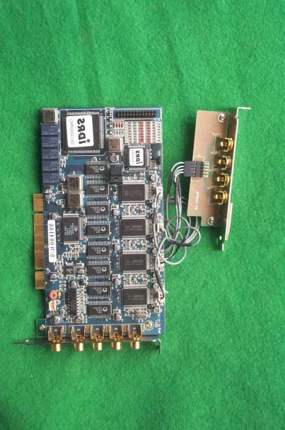
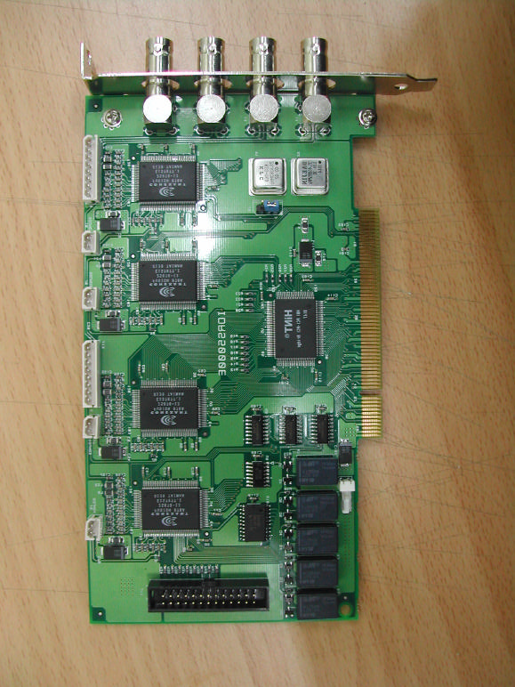
SK TECH CO., LTD. Page 1 of 2 SKT SKTOS-02101 FCC ID : PGZIDRS-5000 External Photographs of EUT SK TECH CO., LTD. Page 2 of 2 SKT SKTOS-02101 FCC ID : PGZIDRS-5000
SK TECH CO., LTD. Page 1 of 1 SKT SKTOS-02101 FCC ID : PGZIDRS-5000 FCC ID Label Sample
SK TECH CO., LTD. Page 1 of 1 SKT SKTOS-02101 FCC ID : PGZIDRS-5000 FCC ID Sample Label & Location Information LABELLING REQUIREMENTS PER 2.928 The Label shown shall be permanently affixed at a conspicuous location on the device and be readily visible to the user at the time of purchase. FCC ID : PGZIDRS-5000 This device complies with part 15 of the FCC Rules. Operation is subject to the following two conditions: (1) This device may not cause harmful interference, and (2) this device must accept any interference received, including interference that may cause undesired operation.
SK TECH CO., LTD. Page 1 of 1 SKT SKTOS-02101 FCC ID : PGZIDRS-5000 Internal Photographs of EUT
SK TECH CO., LTD. Page 1 of 13 SKT SKTOS-02101 FCC ID : PGZIDRS-5000 Certificate of Compliance Test Report No.: SKTOS-02101 NVLAP CODE : 200220-0 Applicant: EASTERN INFO-COM, INC. Applicant Address: Nam Sung B/D, 101-7, Samsung-Dong, Kangnam-Gu, Seoul, Korea Product: VIDEO CAPTURE BOARD FCC ID: PGZIDRS-5000 Model No.: iDRS-5000 Receipt No.: SKE20020318-179 Date of receipt: Mar. 18, 2002 Date of Issue: Oct. 10, 2002 Testing location: SK TECH CO., LTD. 820-2, Wolmoon-Ri, Wabu-Up, Namyangju-Si, Kyunggi-Do, Korea Test Standards: ANSI C63.4 / 2001 Rule Parts: FCC part 15 Subpart B Equipment Class : Class B Digital Device Peripheral Test Result: The above mentioned product has been tested and passed. Prepared by:Y.H.Kang Tested by:J.S.Hyun/Engineer Approved by: K.S.Kim/Manager & Chief Engineer Signature Date Signature Date Signature Date Other Aspects : Abbreviations : · OK, Pass = passed · Fail = failed · N/A = not applicable •This test report is not permitted to copy partly without our permission. •This test result is dependent on only equipment to be used. •This test result is based on a single evaluation of one sample of the above mentioned. •This test report must not be used by the client to claim product endorsement by NVLAP or any agency of the U.S Government. • We certify that this test report has been based on the measurement standards that is traceable to the national or International standards. NVLAP Lab. Code: 200220-0 SK TECH CO., LTD. Page 2 of 13 SKT SKTOS-02101 FCC ID : PGZIDRS-5000 Contents Contents 2 List of Tables 2 List of Figures 2 1. General 3 2. Test Site 3 2.1 Location 3 2.2 List of Test and Measurement Instruments 4 2.3 Test Date 4 2.4 Test Environment 4 3. Description of the tested samples 5 3.1 Rating and Physical Characteristics 5 3.2 Submitted Documents 5 4. Measurement Conditions 6 4.1 Modes of Operation 6 4.2 List of Peripherals 6 4.3 Type of Used cables 7 4.4 Test Setup 7 4.5 Uncertainty 7 5. EMISSION Test 8 5.1 Conducted Emissions 8 5.2 Radiated Emissions 12 List of Tables Table 1 List of test and measurement Equipment 4 Table 2 Test Data, Conducted Emissions 11 Table 3 Test Data, Radiated Emissions 13 List of Figures Figure 1 Spectral Diagram, LINE-PE 9 Figure 2 Spectral Diagram, Neutral-PE 10 SK TECH CO., LTD. Page 3 of 13 SKT SKTOS-02101 FCC ID : PGZIDRS-5000 1. General This equipment has been shown to be capable of compliance with the applicable technical standards and was tested in accordance with the measurement procedures as indicated in this report. We attest to the accuracy of data. All measurements reported herein were performed by SK Tech Co., Ltd. and were made under Chief Engineer’s supervision. We assume full responsibility for the completeness of these measurements and vouch for the qualifications of all persons taking them. 2. Test Site SK TECH Co., Ltd. 2.1 Location 820-2, Wolmoon Ri, Wabu-Up, Namyangju-Si, Kyunggi-Do, Korea The test site is in compliance with ISO/IEC 17025 for general requirements for the competence of testing and calibration laboratories. This laboratory is accredited by NVLAP for NVLAP Lab. Code : 200220-0 and DATech for DAR-Registration No.:TTI-P-G155/97-10 SK TECH CO., LTD. Page 4 of 13 SKT SKTOS-02101 FCC ID : PGZIDRS-5000 2.2 List of Test and Measurement Instruments Table 1 : List of Test and Measurement Equipment l Conducted Disturbance Kind of Equipment Type S/N Calibrated until EMI Receiver ESHS10 862970/019 02.2003 Artificial Mains Network ESH3-Z5 834549/001 10.2002 EMI Receiver ESHS10 835871/002 10.2002 Artificial Mains Network ESH3-Z5 836679/018 10.2002 Conducted Cable N/A N/A N/A l Radiated Disturbance Kind of Equipment Type S/N Calibrated until EMI Receiver ESVS 10 825120/013 02.2003 EMI Receiver ESVS 10 834468/008 11.2002 Spectrum Analyzer R3361A 11730187 07.2003 Amplifier 8447F 3113A05153 06.2003 Log Periodic Antenna UHALP9107 1819 02.2003 Biconical Antenna BBA9106 91031626 02.2003 Antenna Mast 5907 N/A N/A Antenna & Turntable controller 5906 N/A N/A Amp & Receiver connection cables N/A N/A N/A 50 Switcher MP59B 6100214538 N/A 2.3 Test Date Date of Application : Mar. 18, 2002 Date of Test : Apr. 30, 2002 / Oct. 04, 2002 2.4 Test Environment See each test item’s description. SK TECH CO., LTD. Page 5 of 13 SKT SKTOS-02101 FCC ID : PGZIDRS-5000 3. Description of the tested samples The EUT is the Video Capture Board. 3.1 Rating and Physical Characteristics • Display channel : 16channels • Resolution : 320 x 240 • DIO – Sensor 16EA, D/04EA 3.2 Submitted Documents N/A SK TECH CO., LTD. Page 6 of 13 SKT SKTOS-02101 FCC ID : PGZIDRS-5000 4. Measurement Conditions Operating voltage of the EUT is supplied by the PC. ( The PC Input Voltage is AC 120V, 60Hz) 4.1 Modes of Operation The EUT was in the following operation mode during all testing; The output of video distribution detected by camera was transmitted to EUT and the condition of transmission was displayed on PC Monitor. 4.2 List of Peripherals Description Manufacturer Model Name Serial No. FCC ID Personal Computer LG W8S 202KI11027 DoC LCD Monitor Comtec CT-151B B202100494 DoC Keyboard LG LKB-0107 3822B352116 N/A Mouse LG M-S69 HCA20302794 N/A Video Distributor N/A N/A N/A N/A Camera Samsung SDC-310PD M1070206 N/A Adapter (for Monitor) ILAN Elec. Ltd. F1650K N/A N/A Adapter (for Camera) Busung Electronics BSH-1250A N/A N/A SK TECH CO., LTD. Page 7 of 13 SKT SKTOS-02101 FCC ID : PGZIDRS-5000 4.3 Type of Used Cables Description Length Type of shield Manufacturer Remark A/V cable (x4) 1.2m Non-shield N/A Power cable 1.8m Non-shield N/A For PC Video interface cable 1.6m shield N/A Adapter Power cable 1.8m Non-shield N/A For Monitor Adapter Power cable 1.8m Non-shield N/A For Camera Camera interface cable 1.2m Non-shield N/A Keyboard interface cable 1.6m Non-shield N/A Mouse interface cable 1.6m Non-shield N/A 4.4 Test Setup The test setup photographs showed the external supply connections and interfaces. 4.5 Uncertainty 1) Radiated disturbance Uc (Combined standard Un…
Text truncated - open the document above for the full version.
SK TECH CO., LTD. Page 1 of 2 SKT SKTOS-02101 FCC ID : PGZIDRS-5000 Test set up photos Photograph 1: Setup for Conducted Emissions SK TECH CO., LTD. Page 2 of 2 SKT SKTOS-02101 FCC ID : PGZIDRS-5000 Photograph 2: Setup for Radiated Emissions
| # | Rule Parts | Frequency Range | Power Output |
|---|---|---|---|
| 1 | 15B | - | - |

Video Capture Card
Equipment Class
JBP - Part 15 Class B Computing Device Peripheral