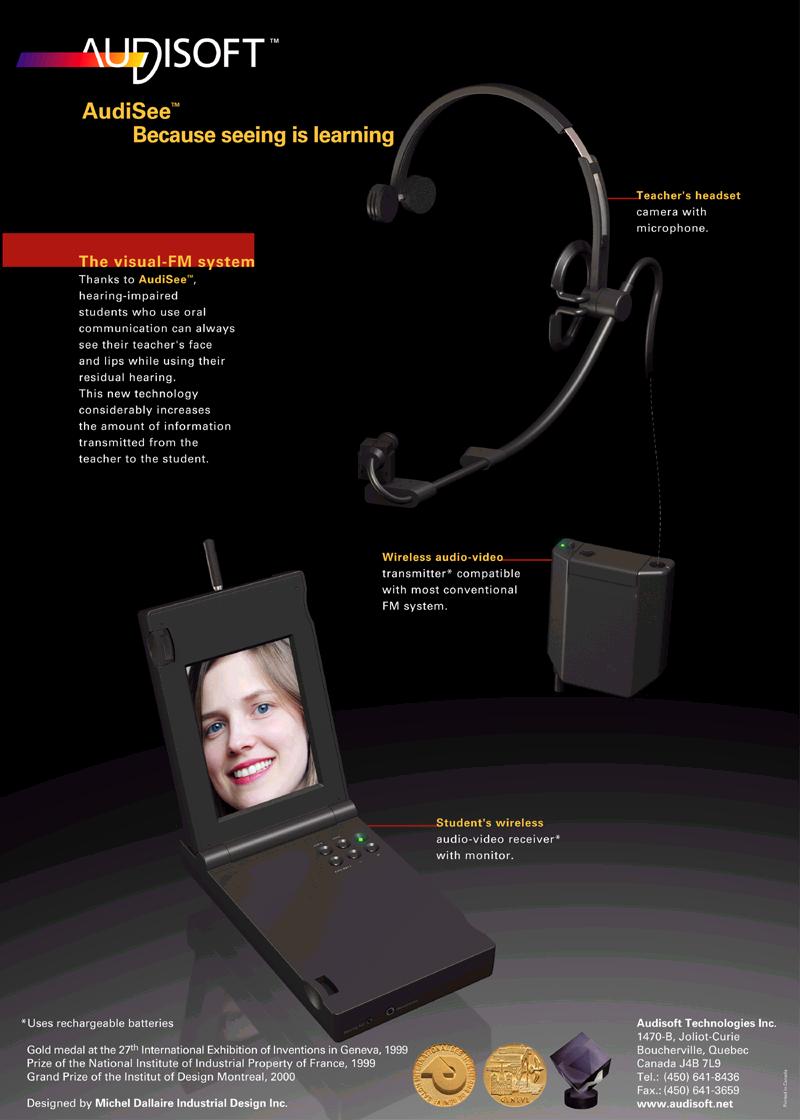
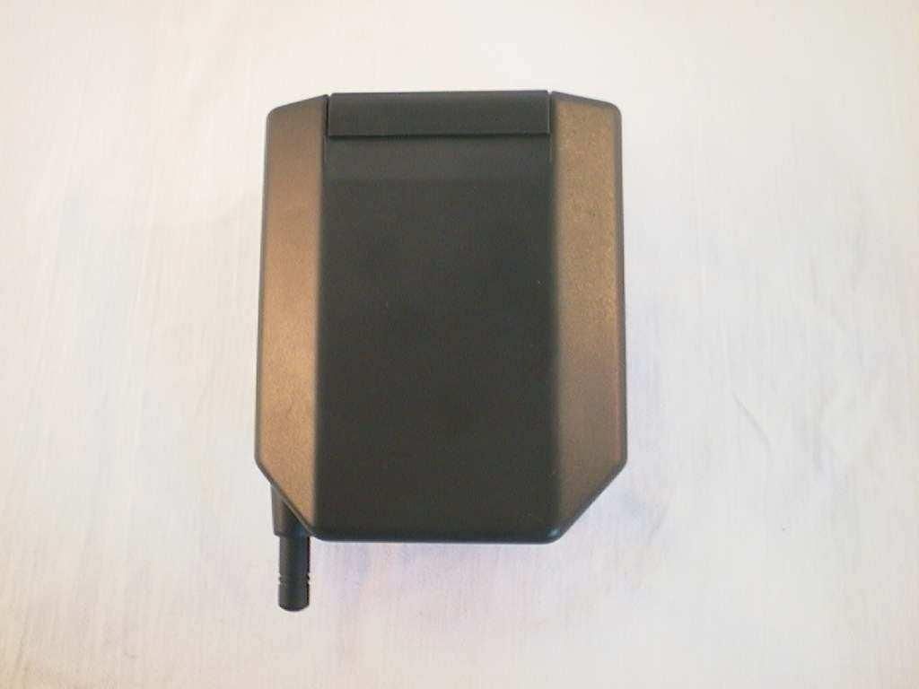
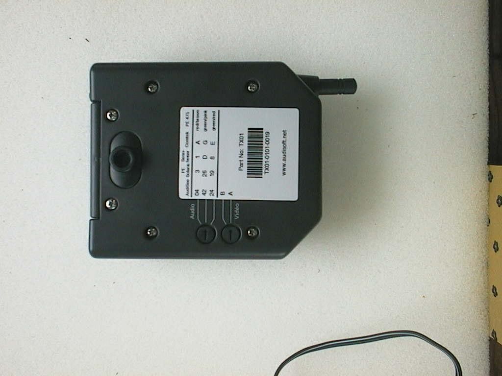
PH9TX01Audio and video transmitter for hearing impaired
Audisoft Technologie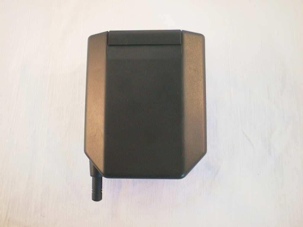
Click to zoom
Application Details
- Equipment Class
- DXX - Part 15 Low Power Communication Device Transmitter
- Date of Grant
- Apr 28, 2002
- Application Purpose
- Original Equipment
- Date of Application
- Mar 13, 2001
- Equipment Note
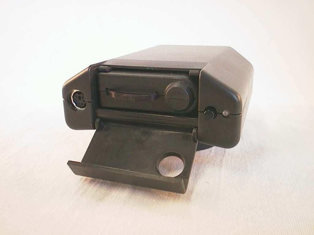
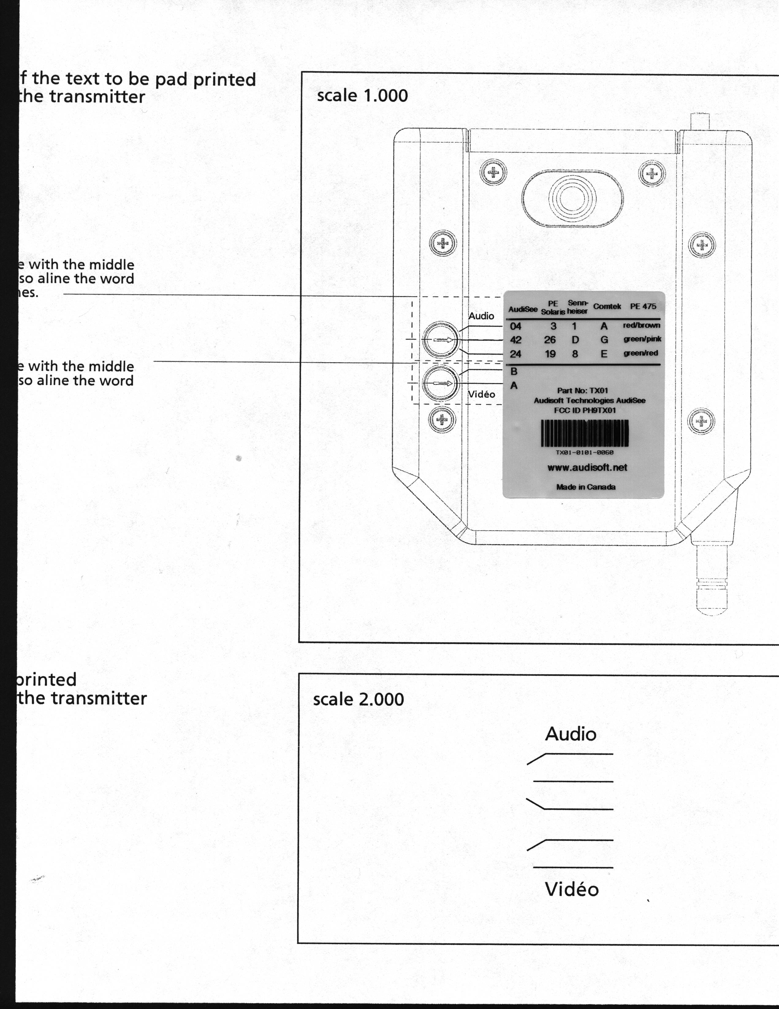
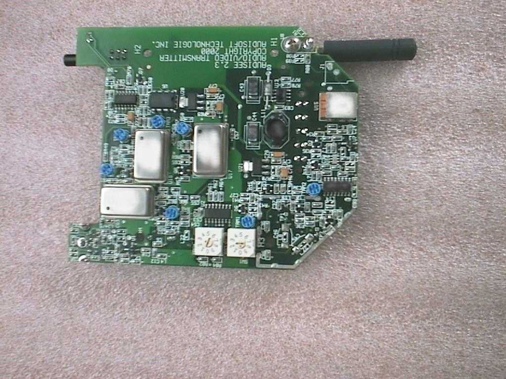
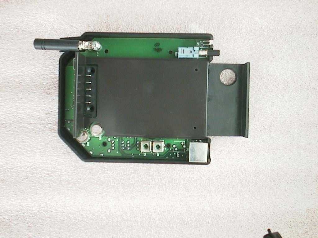
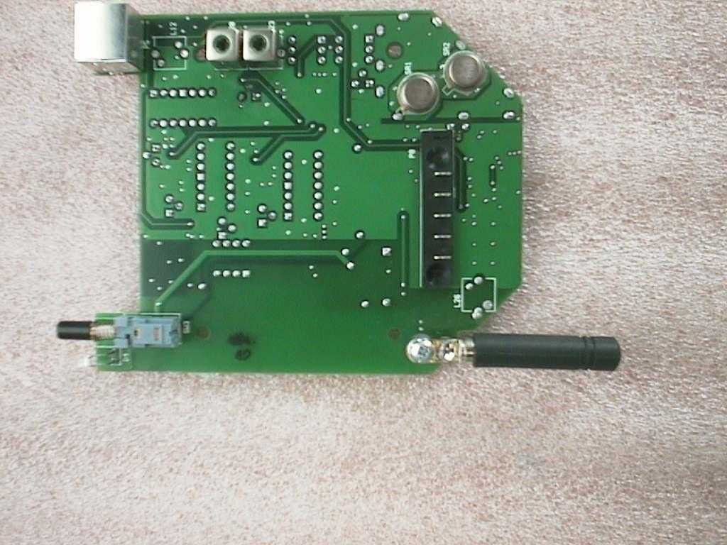
- Audio and video transmitter for hearing impaired
- Frequency Range
- 911.00000000 - 919.00000000
- Company
- Audisoft Technologie
- Country
- Canada
Documents & Files
Document Text
Text extracted from the exhibit documents filed with the FCC. Open a document above to read the original.
Users Manual
1 User’s GuideAudiSee AudiSoft TM Technologies Inc. All rights reser ved.The photocopy, reproduction, translation, electronic stor age and/or transmission in anymanner of any par t of this guide without prior authorization from AudiSoft Technologies Inc. isstr ictly forbidden.All statements, technical information, and recommendations in this manual are believedreliable, but the accuracy and completeness thereof ar e not guaranteed. The information canbe changed at any time without notice. AudiSoft assumes no responsibility for any errors thatmay appear on this document.AudiSoft TM and AudiSee TM are register ed trademarks of AudiSoft Technologies Inc. Printed in Canada 2 TABLE OF CONTENTSTABLE OF CONTENTS ................................................................................. 2 THE AUDISEE SYSTEM ................................................................................ 3 1. The Headset-Camera ................................................................................. 4 a) Assembling the AudiSee headset-camera: ....................................... 4 b) Using the AudiSee headset-camera: ................................................ 4 c) Microphone calibration by an audiologist: .............................................. 5 2. The AudiSee Transmitter ........................................................................... 6 a) Inserting battery into the AudiSee transmitter: ...................................... 6 b) Connecting the headset to the AudiSee transmitter: ............................. 6 c) Activating the AudiSee transmitter: ........................................................ 6 d) Adjusting the AudiSee transmitter’s audio channel and compatibilitywith FM systems: ....................................................................................... 6 f) Fastening and unfastening the AudiSee transmitter clip: ....................... 8 g) Wearing the AudiSee transmitter: .......................................................... 8 3. The AudiSee Monitor-Receiver .................................................................. 9 a) Inserting the battery: ......................................................................... 9 b) Using the AudiSee monitor-receiver: ................................................ 9 c) Using the audio outputs: ................................................................... 9 d) Adjusting the monitor-receiver screen: ........................................... 10 g) Adjusting the AudiSee monitor-receiver’s audio channel: ............... 11 4. THE AUDISEE RECEIVER ...................................................................... 12 5. Batteries and Charger .............................................................................. 13 a) Recharging the transmitter and monitor-receiver batteries : .......... 14 b) Charge status indicator: .................................................................. 14 6. Transport and Storage ............................................................................. 15 TROUBLESHOOTING ................................................................................. 17 Maintenance ................................................................................................. 18 General Maintenance .............................................................................. 18 Cleaning ................................................................................................... 18 SAFETY INFORMATION ............................................................................. 18 APPLYING THE GUARANTEE .................................................................... 19 ADDRESS AND CONTACT INFORMATION ............................................... 20 BAS IC GU AR ANTEE ................................................................................... 21 NOTICE OF COMPLIANCE: FCC AND INDUSTRY CANADA ................... 21 PARTS AND ACCESSORIES ...................................................................... 22 3 THE AUDISEE SYSTEMThe AudiSee TM system allows deaf and hearing-impaired students to see their teacher’s face at all times while using existing hearing abilities to thegreatest degree possible. The AudiSee system takes advantage of the factthat combined audio and visual cues provide at least 30% more informationto students than audio cues alone.This guide is written for users. It explains how to operate AudiSee’s differentmodules. Some sections have been written specifically for audiologists.The system is simple. The teacher wears a headset equipped with a cameraand microphone. The image is displayed via wireless transmission on asmall monitor on the student’s desk, on a larger monitor in front of the class,or on a computer screen. Sound is transmitted directly to the student’s FMsystem.The AudiSee system benefits both student and teacher.AudiSoft TM Technologies’ system can also be used in conferences, again providing many benefits for both speaker and participant.The following table presents the different components required for yourpreferred configuration. Configuration Required elements Reception on the AudiSeemonitor-receiver ! AudiSee headset ! AudiSee transm itter with battery ! AudiSee m onitor-receiver w ith battery ! Battery charger ! Carrying case Reception on a televisionscreen ! AudiSee headset ! AudiSee transm itter with battery ! AudiSee receiver with an AC adapter ! Battery charger ! Television m onitor (not included) Reception on a portablecomputer ! AudiSee headset ! AudiSee transm itter with battery ! AudiSee receiver with battery or ACadapter ! Battery charger ! Carrying case ! Personal com puter with video capturecard (not included) 4 1. THE HEADSET-CAMERA 1) The headset (for assembly)2) Right side of the head with headsetThe headset-camera captures the teacher’s face and voice via the camera ! and microphone " . It is connected by wire # to the transmitter. a) Assembling the AudiSee headset-camera: The arm $ …
Text truncated - open the document above for the full version.
Operational Description
Audisoft Technologies Inc. AUDISEE Technical Specifications AUDISEE Headset Adjustable head band Weight: 150 g Cable length: 90 cm Connector: 6 pins DIN connector Video camera: High Resolution Color camera module Format: 1/3” (.85 cm) Imager, NTSC Active Image Area: 4.69mm Horizontal X 3.54mm Vertical Picture Elements: 510 Horizontal x 492 Vertical Resolution: 330 lines Automatic Exposure: 1/16 to 1/15,734 second Scanning System: 2:1 Interlaced Automatic Image: Brightness, Exposure, White balance Lense: 4mm - 90 degree field of view Sensitivity: Less than 3 lux @ f 1.4 lens Dimensions: L: 1.2 inch (30mm) H: 0.6 inch (17mm) W: 0.6 inch (17mm) Microphone: Unidirectional Back Electret Condenser Microphone Cartridge Sensitivity: -50±4db (0db = 1V/pA, 1kHz) Impedance: Less than 2.2k Ω Directivity: Unidirectional Frequency: 100-12,000 Hz Sensitivity reduction: Within –3 db at 1V S/N ration: More than 55 db Dimension: D : 6 mm H : 5 mm The AudiSee headset-camera comprises a miniature camera and a microphone attached to a support arm placed in front of the speacker’s face. Audisoft Technologies Inc. AUDISEE Technical Specifications AUDISEE Transmitter ON/OFF push button LED indicator for power ON and battery status, varies from green to red. orange indicates approximately 1 hour of use. Battery: DR-108 10.8V /1250 mA Ion-Lithium battery. Typically 7 hours of operation. Connector: 6 positions female DIN connector. Video: Frequencies: Two positions selector for channel A (906 MHz) and B (915 MHz). Modulation: DSB-AM modulation with 80% modulation. Format: NTSC with color sub-carrier at 3.58 MHz. Antenna: Fixed isotropic omni-directional antenna (4 cm x 0.6 cm dia.). Bandwidth: 4 MHz Radiated power: 50 mV/m @ 3m Frequency stability: ±250 KHz Audio: Frequencies: Three positions selector for channel 04 (72.125 MHz), 24 (75.675 MHz) and 42 (72.925 MHz). Modulation : FM modulation ±12 KHz deviation Bandwidth: 25 KHz Antenna: Fixed omni-directional in the headset camera cable. Radiated power: 80 mV/m @ 3m Frequency stability: ±25 ppm Dimensions: 11.5 cm x 9.5 cm x 3.5 cm The AudiSee transmitter is worn at the waist level. It is connected to the headset-camera. It comprises a video/audio transmitter and a battery.
Test Report
Master: ktlPT15249A Date: April 6, 2000 KTL Test Report:0R02313.1 Applicant:Audisoft Technologie 788 Rue Louis Normandin Boucherville, Quebec J4B 3X3 Equipment Under Test:Transmitter (E.U.T.) In Accordance With:FCC Part 15, Subpart C, 15.237 & 15.249 Tested By:KTL Ottawa Inc. 3325 River Road, R.R. 5 Ottawa, Ontario K1V 1H2 Authorized By: G. Westwell, Technologist Date:October 24, 2000 Total Number of Pages:14 Authorized Copy:Soft Copy KTL OttawaFCC PART 15, SUBPART C PROJECT NO.: 0R02313.1 EQUIPMENT: Transmitter Page 2 of 12 Table Of Contents Section 1. Summary Of Test Results.....................................................................................3 Section 2. General Equipment Specification........................................................................5 Section 3. Radiated Emissions...............................................................................................9 Section 4. Test Equipment List...........................................................................................11 Annex A Test Diagrams.....................................................................................................A1 KTL OttawaFCC PART 15, SUBPART C PROJECT NO.: 0R02313.1 EQUIPMENT: Transmitter Page 3 of 12 Section 1.Summary Of Test Results General All measurements are traceable to national standards. These tests were conducted on a sample of the equipment for the purpose of demonstrating compliance with FCC Part 15.249. All tests were conducted using measurement procedure ANSI C63.4-1992. Radiated Emissions were made on an open area test site. New SubmissionProduction Unit Class II Permissive ChangePre-Production Unit GAT Equipment Code THIS TEST REPORT RELATES ONLY TO THE ITEM(S) TESTED. THE FOLLOWING DEVIATIONS FROM, ADDITIONS TO, OR EXCLUSIONS FROM THE TEST SPECIFICATIONS HAVE BEEN MADE. See “ Summary of Test Data”. NVLAP LAB CODE: 100351-0 TESTED BY: DATE: October 24, 2000 Russell Grant, Wireless Group Manager KTL Ottawa Inc. authorizes the above named company to reproduce this report provided it is reproduced in its entirety and for use by the company’s employees only. Any use which a third party makes of this report, or any reliance on or decisions to be made based on it, are the responsibility of such third parties. KTL Ottawa Inc. accepts no responsibility for damages, if any, suffered by any third party as a result of decisions made or actions based on this report. This report applies only to the items tested. KTL OttawaFCC PART 15, SUBPART C PROJECT NO.: 0R02313.1 EQUIPMENT: Transmitter Page 4 of 12 Summary Of Test Data Name Of TestPara. No.Result Conducted Emissions15.207N/A Radiated Emissions15.237, 15.249Complies Footnotes For N/A’s:Batteries KTL OttawaFCC PART 15, SUBPART C PROJECT NO.: 0R02313.1 EQUIPMENT: Transmitter Page 5 of 12 Section 2.General Equipment Specification Manufacturer: Audisoft Technologies Model No.: Transmitter Date Received In Laboratory: October 19, 2000 KTL Identification No.: Item # 41 Frequency Range: Audio:72.0-73.0 MHz, 74.6-74.8 MHz, 75.2-76.0 MHz Video:906.0 MHz, 914.9 MHz Fixed Tunable Bands: 3 + 2 Fixed Frequencies Emission Designator: 5K60F3E, 340KA3F Integral AntennaYesNo Note:If antenna is not integral to transmitter explain method of attachment and type of unique connector: KTL OttawaFCC PART 15, SUBPART C PROJECT NO.: 0R02313.1 EQUIPMENT: Transmitter Page 6 of 12 KTL OttawaFCC PART 15, SUBPART C PROJECT NO.: 0R02313.1 EQUIPMENT: Transmitter Page 7 of 12 KTL OttawaFCC PART 15, SUBPART C PROJECT NO.: 0R02313.1 EQUIPMENT: Transmitter Page 8 of 12 KTL OttawaFCC PART 15, SUBPART C PROJECT NO.: 0R02313.1 EQUIPMENT: Transmitter Page 9 of 12 Section 3.Radiated Emissions Para. No.: 15.237, 15.249 Test Performed By: Russell GrantDate of Test: October 19, 2000 Minimum Standard:Para no. 15.237 & 15.249 The field strengths shall not exceed the following: Fundamental (MHz) Field Strength (mV/m) Field Strength (dBμμV) Harmonic (mV/m) Harmonic (dBμμV) 902-92850940.554 72-768098.11.563.5 Test Results:Complies. The worst-case emission level is 52.5 dBμV/m @ 3m at 1812 MHz. This is 1.5 dB below the specification limit. Measurement Data:See attached table. Maximizing Emission Levels: For hand held equipment or equipment that may be mounted in a variety of positions, the E.U.T. was tested on three orthogonal axis to determine orientation of worst-case emission levels. KTL OttawaFCC PART 15, SUBPART C PROJECT NO.: 0R02313.1 EQUIPMENT: Transmitter Page 10 of 12 Test Data - Radiated Emissions Test Distance (meters) : 3 Range: A Tower Receiver: ESVP RBW(kHz): 120/1000 Detector: Peak Freq. (MHz) Ant. * Pol. (V/H) RCVD Signal (dBμμV/m) Ant. Factor (dB)** Amp. Gain (dB)*** Dist. Corr. (dB) Field Strength (dBμμV/m) Limit (dBμμV/m) Margin (dB) 72.124B/C1V82.59.291.798.16.4 72.124B/C1H79.29.288.498.19.7 144.248B/C1V28.213.842.063.521.5 144.248B/C1H31.813.845.663.517.9 216.372B/C1V24.217.041.263.522.3 216.372B/C1H28.417.045.463.518.1 75.676B/C1V83.08.291.298.16.9 75.676B/C1H78.08.286.298.111.9 151.35B/C1V32.613.946.563.517.0 151.35B/C1H36.013.949.963.513.6 227.026B/C1V14.417.531.963.531.6 227.026B/C1H21.717.539.263.524.3 906.0E/D4V56.832.589.394.04.7 906.0E/D4H54.132.586.694.07.4 1812.0Hrn2V67.533.1-48.152.554.01.5 1812.0Hrn2H64.533.1-48.149.554.04.5 2718.0Hrn2V63.838.0-60.041.854.012.2 2718.0Hrn2H60.238.0-60.038.254.015.8 3624.0Hrn2V56.241.3-57.440.154.013.9 3624.0Hrn2H56.541.3-57.440.454.013.6 4530.0Hrn2V59.043.6-55.547.154.06.9 4530.0Hrn2H58.843.6-55.546.954.07.1 914.9E/D4V56.232.588.794.05.3 914.9E/D4H50.032.582.594.011.5 4574.4Hrn2V47.843.8-55.536.154.017.9 4574.4Hrn2H49.243.8-55.537.554.016.5 5489.3Hrn2V35.246.9-53.628.554.025.5 5489.3Hrn2H39.046.9-53.632.354.021.7 1829.9Hrn2V65.233.2-48.150.354.03.7 1829.9Hrn2H59.833.2-48.144.954.09.1 2744.6Hrn2V69.738.1-60.047.854.06.2 2744.6Hrn2H72.238.1-60.050.354.03.7 3659.5Hrn2V54.541.4-57.638.354.015.7 3659.5Hrn2H58.241.4-57.642.054.012.0 Notes: B/C =Biconical, B/L = Biconilog, L/P = Log-Periodic,…
Text truncated - open the document above for the full version.
Test Setup Photos
Master: ktlPT15249A Date: April 6, 2000 KTL Test Report:0R02313.1 Applicant:Audisoft Technologie 788 Rue Louis Normandin Boucherville, Quebec J4B 3X3 Equipment Under Test:Transmitter (E.U.T.) In Accordance With:FCC Part 15, Subpart C, 15.237 & 15.249 Tested By:KTL Ottawa Inc. 3325 River Road, R.R. 5 Ottawa, Ontario K1V 1H2 Authorized By: G. Westwell, Technologist Date:October 24, 2000 Total Number of Pages:14 Authorized Copy:Soft Copy KTL OttawaFCC PART 15, SUBPART C PROJECT NO.: 0R02313.1 EQUIPMENT: Transmitter Page 2 of 12 Table Of Contents Section 1. Summary Of Test Results.....................................................................................3 Section 2. General Equipment Specification........................................................................5 Section 3. Radiated Emissions...............................................................................................9 Section 4. Test Equipment List...........................................................................................11 Annex A Test Diagrams.....................................................................................................A1 KTL OttawaFCC PART 15, SUBPART C PROJECT NO.: 0R02313.1 EQUIPMENT: Transmitter Page 3 of 12 Section 1.Summary Of Test Results General All measurements are traceable to national standards. These tests were conducted on a sample of the equipment for the purpose of demonstrating compliance with FCC Part 15.249. All tests were conducted using measurement procedure ANSI C63.4-1992. Radiated Emissions were made on an open area test site. New SubmissionProduction Unit Class II Permissive ChangePre-Production Unit GAT Equipment Code THIS TEST REPORT RELATES ONLY TO THE ITEM(S) TESTED. THE FOLLOWING DEVIATIONS FROM, ADDITIONS TO, OR EXCLUSIONS FROM THE TEST SPECIFICATIONS HAVE BEEN MADE. See “ Summary of Test Data”. NVLAP LAB CODE: 100351-0 TESTED BY: DATE: October 24, 2000 Russell Grant, Wireless Group Manager KTL Ottawa Inc. authorizes the above named company to reproduce this report provided it is reproduced in its entirety and for use by the company’s employees only. Any use which a third party makes of this report, or any reliance on or decisions to be made based on it, are the responsibility of such third parties. KTL Ottawa Inc. accepts no responsibility for damages, if any, suffered by any third party as a result of decisions made or actions based on this report. This report applies only to the items tested. KTL OttawaFCC PART 15, SUBPART C PROJECT NO.: 0R02313.1 EQUIPMENT: Transmitter Page 4 of 12 Summary Of Test Data Name Of TestPara. No.Result Conducted Emissions15.207N/A Radiated Emissions15.237, 15.249Complies Footnotes For N/A’s:Batteries KTL OttawaFCC PART 15, SUBPART C PROJECT NO.: 0R02313.1 EQUIPMENT: Transmitter Page 5 of 12 Section 2.General Equipment Specification Manufacturer: Audisoft Technologies Model No.: Transmitter Date Received In Laboratory: October 19, 2000 KTL Identification No.: Item # 41 Frequency Range: Audio:72.0-73.0 MHz, 74.6-74.8 MHz, 75.2-76.0 MHz Video:906.0 MHz, 914.9 MHz Fixed Tunable Bands: 3 + 2 Fixed Frequencies Emission Designator: 5K60F3E, 340KA3F Integral AntennaYesNo Note:If antenna is not integral to transmitter explain method of attachment and type of unique connector: KTL OttawaFCC PART 15, SUBPART C PROJECT NO.: 0R02313.1 EQUIPMENT: Transmitter Page 6 of 12 KTL OttawaFCC PART 15, SUBPART C PROJECT NO.: 0R02313.1 EQUIPMENT: Transmitter Page 7 of 12 KTL OttawaFCC PART 15, SUBPART C PROJECT NO.: 0R02313.1 EQUIPMENT: Transmitter Page 8 of 12 KTL OttawaFCC PART 15, SUBPART C PROJECT NO.: 0R02313.1 EQUIPMENT: Transmitter Page 9 of 12 Section 3.Radiated Emissions Para. No.: 15.237, 15.249 Test Performed By: Russell GrantDate of Test: October 19, 2000 Minimum Standard:Para no. 15.237 & 15.249 The field strengths shall not exceed the following: Fundamental (MHz) Field Strength (mV/m) Field Strength (dBμμV) Harmonic (mV/m) Harmonic (dBμμV) 902-92850940.554 72-768098.11.563.5 Test Results:Complies. The worst-case emission level is 52.5 dBμV/m @ 3m at 1812 MHz. This is 1.5 dB below the specification limit. Measurement Data:See attached table. Maximizing Emission Levels: For hand held equipment or equipment that may be mounted in a variety of positions, the E.U.T. was tested on three orthogonal axis to determine orientation of worst-case emission levels. KTL OttawaFCC PART 15, SUBPART C PROJECT NO.: 0R02313.1 EQUIPMENT: Transmitter Page 10 of 12 Test Data - Radiated Emissions Test Distance (meters) : 3 Range: A Tower Receiver: ESVP RBW(kHz): 120/1000 Detector: Peak Freq. (MHz) Ant. * Pol. (V/H) RCVD Signal (dBμμV/m) Ant. Factor (dB)** Amp. Gain (dB)*** Dist. Corr. (dB) Field Strength (dBμμV/m) Limit (dBμμV/m) Margin (dB) 72.124B/C1V82.59.291.798.16.4 72.124B/C1H79.29.288.498.19.7 144.248B/C1V28.213.842.063.521.5 144.248B/C1H31.813.845.663.517.9 216.372B/C1V24.217.041.263.522.3 216.372B/C1H28.417.045.463.518.1 75.676B/C1V83.08.291.298.16.9 75.676B/C1H78.08.286.298.111.9 151.35B/C1V32.613.946.563.517.0 151.35B/C1H36.013.949.963.513.6 227.026B/C1V14.417.531.963.531.6 227.026B/C1H21.717.539.263.524.3 906.0E/D4V56.832.589.394.04.7 906.0E/D4H54.132.586.694.07.4 1812.0Hrn2V67.533.1-48.152.554.01.5 1812.0Hrn2H64.533.1-48.149.554.04.5 2718.0Hrn2V63.838.0-60.041.854.012.2 2718.0Hrn2H60.238.0-60.038.254.015.8 3624.0Hrn2V56.241.3-57.440.154.013.9 3624.0Hrn2H56.541.3-57.440.454.013.6 4530.0Hrn2V59.043.6-55.547.154.06.9 4530.0Hrn2H58.843.6-55.546.954.07.1 914.9E/D4V56.232.588.794.05.3 914.9E/D4H50.032.582.594.011.5 4574.4Hrn2V47.843.8-55.536.154.017.9 4574.4Hrn2H49.243.8-55.537.554.016.5 5489.3Hrn2V35.246.9-53.628.554.025.5 5489.3Hrn2H39.046.9-53.632.354.021.7 1829.9Hrn2V65.233.2-48.150.354.03.7 1829.9Hrn2H59.833.2-48.144.954.09.1 2744.6Hrn2V69.738.1-60.047.854.06.2 2744.6Hrn2H72.238.1-60.050.354.03.7 3659.5Hrn2V54.541.4-57.638.354.015.7 3659.5Hrn2H58.241.4-57.642.054.012.0 Notes: B/C =Biconical, B/L = Biconilog, L/P = Log-Periodic,…
Text truncated - open the document above for the full version.
Contact Information
Applicant
Luc Ducas(Vice-president)
Technical Contact
Audisoft TechnologieLuc Ducas
[email protected](450)641-8436
1470-B Joliot-Curie · Boucherville · Canada
Non-Technical Contact
Audisoft TechnologieLuc Ducas
[email protected](450)641-8436
Test Firm
Nemko Canada Inc.Stuart Beck
Technical Specifications
| # | Rule Parts | Frequency Range | Power Output |
|---|---|---|---|
| 2 | 15C | 911 MHz - 919 MHz | - |
Other Applications from Audisoft Technologie
PH9RX01
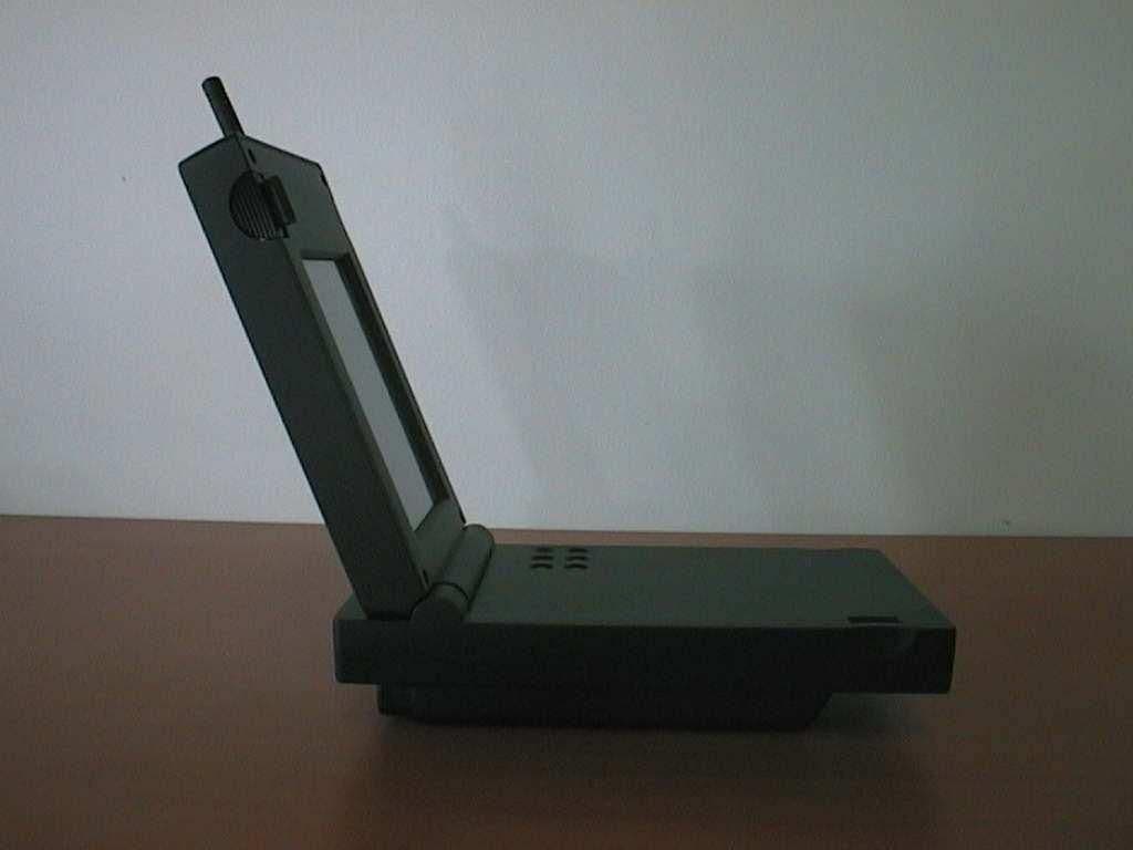
Mar 22, 2001Audio video monitor-receiver for hearing impaired
Equipment Class
CYY - Communications Receiver used w/Pt 15 Transmitter