Text extracted from the exhibit documents filed with the FCC. Open a document above to read the original.
Getting Started with FEATURES GUIDE A simple, step-by-step guide to setting up and using your new ArialPhone Cover Comps rev.1 2/8/01 3:16 PM Page 1 Contents GETTING STARTED................................................................... 00 FIRST THINGS FIRST Overview:Introduction to ArialPhone.........................................00 Requirements for using ArialVoice software ..................................00 Overview:opening the box, parts list .........................................00 ARIALPHONE HARDWARE Identifying ArialPhone components ..............................................00 Assembling the phone hardware ...................................................00 • Charging the batteries ............................................................00 • Assembling the earset ............................................................00 • Assembling the headset .........................................................00 ARIALVOICE SOFTWARE INSTALLATION Running the installation program ..................................................00 • Selecting an address book .....................................................00 • Specifying confirmation options ............................................00 • Specifying dialing options .....................................................00 • Using the microphone wizard.................................................00 Verifying communication between hardware and software ............00 UP AND RUNNING Customizing ArialPhone for multiple users...................................00 Interpreting ArialPhone tones........................................................00 Asking Arial for help .....................................................................00 Specifying ArialVoice settings.......................................................00 Recharging and replacing the batteries .........................................00 Tips for ArialPhone performance...................................................00 MANAGING YOUR PHONE BOOK Overview:Voice recognition technology ....................................00 Revised TOC 2/12/01 2:22 PM Page 1 Overview:How ArialPhone uses the Outlook/Windows address book..............................................................................00 Adding an entry to your address book ..........................................00 Improving the accuracy of voice recognition ................................00 Updating your address book .........................................................00 ANSWERING CALLS WITH ARIALPHONE Overview:How ArialPhone alerts you to incoming calls............................................................................00 Placing a call on hold ...................................................................00 Using call waiting .........................................................................00 Ending a call .................................................................................00 PLACING A CALL Overview: How ArialPhone responds to your commands .................................................................................00 Calling by name or location ..........................................................00 Calling by telephone number ........................................................00 Navigating a phone tree ................................................................00 Placing a 3-way call ......................................................................00 Placing a call on hold ...................................................................00 Using call waiting .........................................................................00 Ending a call .................................................................................00 Dialing without ArialVoice.............................................................00 PLACING A CALL OVER THE INTERNET Overview:Internet telephone technology....................................00 Making a call over the Internet ......................................................00 Revised TOC 2/12/01 2:22 PM Page 2 ADJUSTING THE VOLUME Using the microphone wizard........................................................00 Muting a call .................................................................................00 TROUBLESHOOTING ArialPhone doesn’t understand my commands .............................00 ArialPhone doesn’t recognize names in my phone book ...............00 ArialPhone can’t dial my call.........................................................00 The volume is too loud or too soft ................................................00 My call breaks up..........................................................................00 SAFETY INFORMATION Overview: How ArialPhone operates ..........................................00 Safety guidelines ...........................................................................00 Caring for your phone ...................................................................00 • Protecting your phone............................................................00 • Disposing of batteries ............................................................00 FCC notice ....................................................................................00 CONTACTING TECHNICAL SUPPORT.................................... 00 INDEX.......................................................................................... 00 FCC notice This device complies with Part 15 of the FCC rules and with RSS-210 of Industry Canada. Operation is subject to the following two conditions: 1. This device does not cause harmful interference, and 2. This device must accept any interference received, including interference that may cause undesired operation. Warning:Changes or modifications not expressly approved by the party responsible for compliance could void the user’s authority to operate the equipment. Revised TOC 2/12/01 2:22 PM Page 3
3 Hawthorn Parkway, Vernon Hills, IL 60061 Phone 847-573-9925. Fax 847-573-9926. FCC AUTHORIZATION January 31 2001Time:15:29 To:FCC Aut horization & Evaluation Division 7435 Oakland Mills Road Columbia, MD 21045-0429 From: Gerald HansbergerPhone: 847-573-9925 VP OperationsFax:847-573-9926 Applicant: ArialPhone Corporation E-Mail: [email protected] Dear Ladies and/or Gentlemen: I appoint Kenneth L. Boston and James Blaha at L.S. Compliance, Inc., to act as an agent in the preparation of applications under Part 15 of the rules and regulations of the Federal Communication Commission. I certify that the exhibitions properly describe the device being submitted under this application and will implement any changes described in the test report. The labels described will be affixed to each item. The following statement is required by the Federal Communications Commission: By checking Yes , the applicant certifies that, in the case of an individual applicant, he or she is not subject to a denial of federal benefits, that included FCC benefits, pursuant to section 5301 of the Anti-Drug Abuse Act of 1988, 21 U.S.C 853(a), or, in the case of a non-individual applicant (e.g. corporation, partnership, or other unincorporated association), no party to the application is subject to a denial of federal benefits, that includes FCC benefits, pursuant to that section. X YES______ NO Dated this 31st day of January, 2001 By: Gerald L. Hansberger Title:VP Operations, ArialPhone T Corporation Phone: 847-573-9925 Sincerely, 3 Hawthorn Parkway, Vernon Hills, IL 60061 Phone 847-573-9925. Fax 847-573-9926. 2
Base Station Block DiagramEarset Block Diagram DAA CODEC USB Interface Micro Controller Computer Audio In Audio Out ADPCM Control Bus USB Radio Hummingbird Chipset CODEC ADPCM Phone Line Caller ID Tip Ring Audio Switch Network Switch Control Radio Hummingbird Chipset CODEC Speaker Microphone
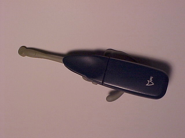
ArialPhone Corporation FCC ID#: PHIAP100 Photo 1 Exterior View of ArialPhone Headset
ArialPhone Corporation FCC ID#: PHIAP100 Photo 2 Exterior View of ArialPhone Headset Ear Clip and Ear Microphone Side Voice Microphone on Left Side
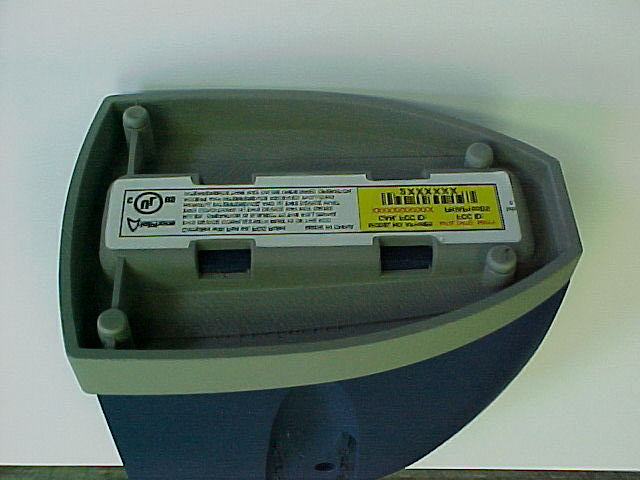
ArialPhone Corporation FCC ID#: PHIAP100 Photo 3 Exterior View of ArialPhone Headset Battery Clip Removed to Expose FCC ID Label
ArialPhone Corporation FCC ID#: PHIAP100 Photo 5 Interior View of ArialPhone Headset Open for Inspection
ArialPhone Corporation FCC ID#: PHIAP100 Photo 6 Interior View of ArialPhone Headset Close-Up of PCB, Antenna located on the Left
ArialPhone Corporation FCC ID#: PHIAP100 Photo 7 Interior View of ArialPhone Headset Close-Up of flipped PCB, Wires go to EarPiece Microphone RF Section in center of PCB
ArialPhone Corporation FCC ID#: PHIAP100 Photo 8 Interior View of ArialPhone Headset Close-Up of RF Antenna
L.S. RESEARCH Inc. HIGH TECHNOLOGY ELECTRONIC CONSULTANTS File:137578 CONFIDENTIAL Page 1 of 1 February 22, 2001 Arial Earset Theory of Operation The Arial Earset is a direct sequence spread spectrum (DSSS) wireless audio device based on the Conexant Hummingbird chipset. It has a single control button w hich causes it to link to a companion base station and exchange full duplex voice communication. A time division duplex (TDD) scheme is used to give full duplex audio operation while only occupying a single RF channel. It can operate on any one of 20 preassigned channels in the 902 to 928 MHz ISM band. The user has no control over channel assignment. When a link is established the chipset monitors signal quality and dynamically changes channels to avoid interference. Conducted output power is a maximum of +21dBm.
L. S. Compliance, Inc. L. S. Research, Inc. Request for FCC Opinion and Ruling PAGE: 1 of 4 Date : January 23, 2001 To :Mr. Kwok Chan Company :FCC Laboratory Phone :301 - 362 - 3055 Email:[email protected] From :Jim Blaha Company :L. S. Research and L. S. Compliance, Inc. Phone :262 - 375 - 4400 Fax :262 - 375 - 4248 Email: [email protected] Subject: FCC Interpretation of TCB Testing Scope Dear Kwok, This brief memo is prepared based on our telephone conversation of January 22 nd . We discussed the interpretation of the TCB Scope in relationship to product certification. The outcome of our discussion ended with your request to have us submit a brief overview of our product. This overview includes product description, photos and power calculations. Based on the following information, it is the opinion of our laboratory that this product qualifies for TCB Certification. We respectfully request your opinion. Please respond by reply email of your recommendations for the testing requirements to achieve FCC certification. Respectfully submitted, James Blaha Sr. Vice-President Quality Manager Page 2 Product Description: 902-928 MHz Transceiver based on Direct Sequence Spread Spectrum. Time Division Duplexed. Digital Voice Transmission and Receiver. Product name for marketing: Arial Phone Market Application: Home Office and Small Business Phone System. Photo’s of Headset: Position of Headset in relationship to Cranium Page 3 Close-up of Headset Close-up of PCB and Antenna Page 4 Headset Dimensions: Unit Size of: 1.25 inches - Height / 6 inches - Width / 1 inch Depth Separation from Cranium, based on photo’s supplied: 3 cm. Headset RF Power: Conducted RF power at the antenna port: 17 dBm Radiated power ( F.S. ) at 3 meters: 108 dBmicroV / m Calculated Equivalent ERP: 12.8 dBm or 19.05 mW - peak L. S. Research and L. S. Compliance opinion on FCC Certification Testing: Based on the above photos and calculations, we are of the opinion that this Phone Headset product may be tested at L. S. Compliance following FCC Part 15.247 requirements with certification filing and approval to be conducted by a TCB. We base this opinion on the TCB – Appendix “A”, Exclusion List revised on December 18, 2000. Specifically, Section VI – Part 15 Portable Transmitters, Paragraph e) , vii) which states TCB’s are excluded if the antenna is “ less than 2.5 cm from a person’s body ” AND the “ peak conducted or peak radiated ( EIRP ) output power exceeds 25 mW for the 900 MHz band ”. Our calculations for both are below these limits and therefore nullify this exclusion. Please respond by email with your opinion on this filing. Sincerely, L. S. Research, Inc.L. S. Compliance, Inc.L. S. Compliance, Inc. Brian PettedJames BlahaKen Boston, PE VP EngineeringSr. Vice-PresidentEMC Lab Manager Quality Manager
Series of emails to/from Mr. Kwok Chan providing FCC Opinion and Ruling on TCF Filing and SAR Testing. Sorry about that, please see attached. >>> "Ji m Blaha" <[email protected]> 01/30/01 12:38PM >>> Hi Kwok, You attached inform on SAR Labs. Your received email did not have this info attached. May I request you send it again. Tha nk yo u, Jim Blaha L. S. Compliance, Inc. ----- Original Message ----- From: Kwok Chan <kc ha n@ fcc. gov> To: <[email protected]> Cc: Kwok Chan <[email protected]> Sent: Monday, January 29, 2001 1:50 PM Subject: Re: Interpretation of TCB testing scope > > Based on the info in your e-mail, it does not appear SAR evaluation is needed for this device to satisfy the requirements of 15.247(b)(4). Attached is info on some SAR labs for future use. We do not approve SAR labs, these are just the ones we know. You will need to call the labs regarding the types of services that are available. > > Kwok Chan > > > >>> "Ji m Blaha" <[email protected]> 01/29/01 02:41PM >>> > January 29, 2001 > > Dear Kwok, > > Tha nk yo u for yo ur quic k responsiveness. > We will submit this filing through the FCC Electronic Filing System. > > However, I do have one more question.... > > Based on the information we shared with you, do we need SAR testing on this > product ?????? > If Yes, then I respectfully request a FCC Aproved Reference List of SAR > Testing Llaboratories > that I ma y co ntact for Sched uling a nd Q uota tions. > > Sincerely, > > Jim Blaha > L. S. Compliance, Inc. > ----- Original Message ----- > From: Kwok Chan <kcha n@fcc. gov> > To: <[email protected]> > Cc: Kwok Chan <[email protected]>; Raymond Laforge <[email protected]> > Sent: Monday, January 29, 2001 10:10 AM > Subject: Interpretatio n of TCB testi ng scope > > > > Mr. Blaha: > > The information in your e-mail (attached below) indicates this device has 17 > dBm (50 mW) conducted output and a 3-meter field strength of 108 dBuV/m. > This field strength converts to 18.9 mW EIRP and is equivalent to 11.5 mW > ERP. The ERP value (19.05 mW) indicated in your e-mail appears to be in > error . > > As you have already indicated in your e-mail, Section VI (e) (vii) of the > TCB Exclusion List does not allow TCB to approve spread spectrum > transmitters operating in the 900 MHZ band if the device or its antenna is > less than 2.5 cm from a person's body when either the peak conducted or peak > radiated (EIRP) output is above 25 mW. The peak conducted output as > indicated in your e-mail is 50 mW, which is above 25 mW; therefore, it does > not qualify for TCB approval. > > The headset dimension section of your e-mail indicates there is about 3 cm > separation between the cranium and "some portions of the device" that has > not been clearly defined. Both Sections VI (e) (vi) and (vii) of the TCB > Exclusion List require a device and its antenna to provide at least 5 cm and > 2.5 cm respectively from a person's body. Since this device designed to be > worn next to a person's ear, it does not appear it would satisfy the > requirements of these two sections. Based on the info provided, this device > would not qualify for TCB approval. > > Kwok Chan > > >
Arial Earset.sch-1 - Thu Jan 25 08:03:54 2001
. . . . . . . . . . . . . . . . . . . L. S. Compliance, Inc. Compliance Testing of: Arial Aphone-100 Prepared for: ArialPhone L.L.C. Gerald L Hansberger Test Report Number: Date(s) of Testing: January 23-24, 2001 All results of this report relate only to the items that were tested. L. S . C o mp lia nc e , Inc . W66 N220 Commerce Court Cedarburg, Wisconsin 53012 Phone: 414 - 375 - 4400 Fax: 414 - 375 - 4248 L. S. COMPLIANCE, Inc. FCC ID: LSC- 1 This report may not be reproduced, except in full, without written approval of L. S. Compliance, Inc. L. S. COMPLIANCE, Inc. FCC ID : PHIAP100 LSC-Page 2 of 24 INDEX SectionDescriptionPage # Cover Page Index1 Description of Measurement Facilities2 Accreditation certificate; A2LA3 Signature Page4 2.3Summary of Test Report5 2.4Introduction5 2.5Purpose6 2.6Conducted Emissions6 2.7Radiated Emission Test Setup7 2.8Radiated Emission Test Procedure7 2.9Test Equipment Utilized8 2.10Restricted Bands Affected9 2.11Photos taken of testing10 2.12Conclusions11 2.13Test Equipment List12 Appendic es ASample Calculations:13 i.Calculation of Radiated Emissions Limits14 BData Charts15 CGraphs18 L. S. COMPLIANCE, Inc. FCC ID : PHIAP100 LSC-Page 3 of 24 D ESCRIPTION OF M EASUREMENT F ACILITIES Site on File with the FCC ID Number: 31040/SIT 1300F2 “ The site referenced above has been found to comply with the test site criteria found in ANSI C63.4-1992 and 47CFR Section 2.948.” L. S. COMPLIANCE, Inc. FCC ID : PHIAP100 LSC-Page 4 of 24 L. S. COMPLIANCE, Inc. FCC ID : PHIAP100 LSC-Page 5 of 24 SIGNATURE PAGE Testing By:12 feb 2001 Thomas T. Lee Date Testing By:12 feb 2001 Kenneth L. Boston PE Date Prepared by: Approved by 12 feb 2001 Kenneth L. Boston, EMC Lab ManagerDate PE #31926 Registered Professional Engineer (State of Wisconsin) L. S. COMPLIANCE, Inc. FCC ID : PHIAP100 LSC-Page 6 of 24 2.3 S UMMARY OF T EST R EPORT MANUFACTURER:ArialPhone L.L.C. MODEL:APhone-100 SERIAL:engineering sample DESCRIPTION:Voice based wireless earset FREQUENCY RANGE:902-928 MHz The Arial APhone-100 was found to meet the radiated emission specification of Title 47 CFR FCC, Part 15, subpart C. for an intentional radiator The Arial APhone-100 was also found to meet the radiated emission specification of Title 47 CFR, FCC Part 15, subpart B for emissions with regards to the receiver and digital sections of the product. This product is a composite device, with the digital sections subject to verification. Therefore this technical report will primary contain data that is pertinent to the certification of the transmitter section of the product. 2.4 I NTRODUCTION On January 23 and 24, of 2001, a series of Radiated Emissions tests were performed on a sample model of the Aphone-100, a spread spectrum transceiver designed for hands free communication with a base station. These tests were performed using the test procedures outlined in ANSI C63.4-1992 for intentional radiators, and in accordance with the requirements set forth in FCC Part 15.247 for a direct sequence spread spectrum transmitter. Tests were also performed as outlined in ANSI C63.4-1992 for non-intentional radiators, in order to verify compliance with the limits set forth in part 15.109 for and to allow verification of emissions for the digital section of the product. These tests were performed by Thomas T. Lee and Kenneth L. Boston PE, of L. S. Compliance, Inc. L. S. COMPLIANCE, Inc. FCC ID : PHIAP100 LSC-Page 7 of 24 2.5 P URPOSE The above mentioned tests were performed in order to determine the compliance of the Aphone-100 product with limits contained in various provisions of Title 47 CFR, FCC Part 15, including: 15.20915.247b15.247e 15.20515.247c15.109 15.247a215.247d Various of these tests, including the conducted RF out the antenna port and the jamming margin test are contained in an additional test report that is attached to this report. All radiated emissions tests were performed to measure the emissions in the frequency bands described by the above sections, and to determine whether said emissions are below the limits established by the above sections. These tests were performed in accordance with the procedure described in the American National Standard for methods of measurement of Radio-Noise Emissions from Low-Voltage Electrical and Electronic Equipment in the Range of 9 kHz to 40 GHz (ANSI C63.4-1992). Another document used as reference for the EMI receiver specification was the International Special Committee on Radio Interference (CISPR) number 16-1 (1993). 2.6Conducted (AC LINE) Test Setup and measurements Due to the fact that the product operates on internal battery power, no conducted emissions tests were performed at 0.45 to 30 MHz on AC lines. L. S. COMPLIANCE, Inc. FCC ID : PHIAP100 LSC-Page 8 of 24 2.7 R ADIATED E MISSIONS T EST S ETUP The test sample was operated within the 3 meter Semi-Anechoic, FCC listed chamber located at L.S. Compliance in Cedarburg, WI. The sample was positioned on a small wood pedestal, which was centered on the flush-mounted 2m diameter metal turntable. The test sample was operated on its internal battery supply. The test sample was configured to run in a continuous transmit mode during the 15.247 and 15.205 measurements. One test sample was set to operate on either channel 01 (low), channel 09(medium) or channel 13 (high) while being tested as an intentional radiator, in order to determine compliance within a frequency range of 902-928 MHz, as dictated by FCC part 15.31m Please refer to Section 2.15 for pictures of the test setup. 2.8 R ADIATED E MISSION T EST P ROCEDURE The fundamental and spurious (harmonic) emissions of the transmitter were tested for compliance to Title 47 CFR, FCC Part 15.247c limits for Direct Sequence Spread Sprectrum systems, and the 15.205 general limits, within the restriced bands. For the calculations used to determine the 1 meter limits, see Appendix A. The test sample was tested from the lowest frequency generated by the transmitter to the 10th harmonic of…
Text truncated - open the document above for the full version.
.......... . . . . . . . . . . LS Research Inc. Airal Phone Earset FCC ID: PHIAP100 Part 15.247 Type Acceptance, Conducted Measurements prepared for Arial Phone Revision 1.0 L.S. RESEARCH Inc. 2 of 51 HIGH TECHNOLOGY ELECTRONIC CONSULTANTS FCC ID: PHIAP100 WE HAVE DESIGNS ON THE FUTURE W66 N220 Commerce Court, Cedarburg, Wisconsin 53012 • 414-375-4400 • FAX 414-375-4248 Email: [email protected] www.lsr.com Table of Contents I. Project Information ............................................................................................................................................... 3 II. FCC Conducted Tests ...................................................................................................................................... 5 A. Part 15.247 .................................................................................................................................................... 5 1. 15.247 (a) (2) Emission 6 dB Bandwidth...................................................................................................... 5 2. 15.247 (b) (1) Output Power ....................................................................................................................... 10 3. 15.247 (b) (3) Effective Radiated Power..................................................................................................... 14 4. 15.247 (c) Spurious Modulation Products................................................................................................... 14 5. 15.247 (d) Power Spectral Density ............................................................................................................. 28 6. 15.247 (e) Processing Gain ......................................................................................................................... 33 III. Critical Equipment List ................................................................................................................................... 50 IV. Equipment Uncertainties ................................................................................................................................. 50 V. Bit Error Ratio Test Software ......................................................................................................................... 51 L.S. RESEARCH Inc. 3 of 51 HIGH TECHNOLOGY ELECTRONIC CONSULTANTS FCC ID: PHIAP100 WE HAVE DESIGNS ON THE FUTURE W66 N220 Commerce Court, Cedarburg, Wisconsin 53012 • 414-375-4400 • FAX 414-375-4248 Email: [email protected] www.lsr.com Airal Phone Earset I. Project Information Project: Airal PhoneEarset Arial Systems Contact: Company: Arial Systems Corporation Full Name: Marc Cygnus Job Title: Senior Programmer Analyst 3 Hawthorn Parkway Vernon Hills, IL 60061 Bus: (847)-573-9925 ext. 228 Bus Fax: (847) 573-9926 E-mail: [email protected] LS Research Contact: Bill Steinike, Operations Manager Brian Petted, Vice President of Engineering Voice: 262-375-4400 Fax: 262-375-4248 Email: [email protected] Report Date: 2/22/01 Revision: 1.0 Proposal #: Proposal File: Arial Phone Job Number: L.S. RESEARCH Inc. 4 of 51 HIGH TECHNOLOGY ELECTRONIC CONSULTANTS FCC ID: PHIAP100 WE HAVE DESIGNS ON THE FUTURE W66 N220 Commerce Court, Cedarburg, Wisconsin 53012 • 414-375-4400 • FAX 414-375-4248 Email: [email protected] www.lsr.com Signatures: Technical Approval L.S. RESEARCH Inc. 5 of 51 HIGH TECHNOLOGY ELECTRONIC CONSULTANTS FCC ID: PHIAP100 WE HAVE DESIGNS ON THE FUTURE W66 N220 Commerce Court, Cedarburg, Wisconsin 53012 • 414-375-4400 • FAX 414-375-4248 Email: [email protected] www.lsr.com II. FCC Conducted Tests A. Part 15.247 1. 15.247 (a) (2) Emission 6 dB Bandwidth a) Test Requirement The 6 dB bandwidth of the Equipment emission must be greater than 500 kHz. kHzB dB 500 6 > − b) Test Configuration The test configuration is presented below: HP E4404B Spectrum Analyzer #CC00221C Transmitter Under Test RG-316 Launch / SMA SMA / N L.S. RESEARCH Inc. 6 of 51 HIGH TECHNOLOGY ELECTRONIC CONSULTANTS FCC ID: PHIAP100 WE HAVE DESIGNS ON THE FUTURE W66 N220 Commerce Court, Cedarburg, Wisconsin 53012 • 414-375-4400 • FAX 414-375-4248 Email: [email protected] www.lsr.com c) Test Conditions: Equipment Under Test The equipment under test is tunable and is set to 3 different channels, one representing the minimum tunable frequency, one representing a midband frequency and one representing the maximum tunable frequency. The frequencies and their hexadecimal channel designators are presented below for reference. Channel 1: 904.8 MHz Channel 9: 914.5 MHz Channel 13: 925.8 MHz Test indications under these three frequency conditions are presented. The output power is fixed to its maximum , worst-case value. d) Test Conditions: Instrumentation Conditions The readings indicated on the spectrum analyzer are a result of a marker search function which determines the 6 dB bandwidth of the indicated spectrum. The spectrum analyzer display indicates its conditions as follows: Center: Center Frequency Span: Frequency Span Res BW: Resolution Bandwidth VBW: Video (averaging) Bandwidth Sweep: Frequency Sweep time over indicated frequency Span. L.S. RESEARCH Inc. 7 of 51 HIGH TECHNOLOGY ELECTRONIC CONSULTANTS FCC ID: PHIAP100 WE HAVE DESIGNS ON THE FUTURE W66 N220 Commerce Court, Cedarburg, Wisconsin 53012 • 414-375-4400 • FAX 414-375-4248 Email: [email protected] www.lsr.com e) Test Indications Test Condition: Channel 1: 904.80M Hz Test Limit: 500 kHz, minimum. Test Indication: 1.546 MHz Test Outcome: 1.546 MHz > 500 kHz → PASS L.S. RESEARCH Inc. 8 of 51 HIGH TECHNOLOGY ELECTRONIC CONSULTANTS FCC ID: PHIAP100 WE HAVE DESIGNS ON THE FUTURE W66 N220 Commerce Court, Cedarburg, Wisconsin 53012 • 414-375-4400 • FAX 414-375-4248 Email: [email protected] www.lsr.com Test Condition: Channel 9: 914.5 MHz Test Limit: 500 kHz, minimum. Test Indication: 1.571 MHz Test Outcome: 1.571 MHz > 500 kHz → PASS L.S. RESEARCH Inc. 9 of 51 HIGH TECHNOLOGY ELECTRONIC CONSULTANTS FCC ID: PHIAP100 WE HAVE DESIGNS ON THE FUTURE W66 …
Text truncated - open the document above for the full version.
W66 N220 Commerce Court · Vernon Hills, Wisconsin · United States
| # | Rule Parts | Frequency Range | Power Output |
|---|---|---|---|
| 1 | 15C | 904.8 MHz - 925.8 MHz | 54.00 mW |

Cordless Earset Basestation
Equipment Class
DSS - Part 15 Spread Spectrum Transmitter