FCCID.CO- FCC ID Database
HomeCompaniesEquipment ClassesSearch

© 2026 FCC ID Database. All rights reserved.

AboutContactData sourced from FCC public records
  1. Home/
  2. ArialPhone L.L.C./
  3. PHIAP100BS

PHIAP100BSCordless Earset Basestation

ArialPhone L.L.C.
Cordless Earset Basestation - FCC ID PHIAP100BS - ArialPhone L.L.C.
Click to zoom

Application Details

Equipment Class
DSS - Part 15 Spread Spectrum Transmitter
Date of Grant
Jun 18, 2001
Application Purpose
Original Equipment
Date of Application
Jun 18, 2001
Equipment Note
Cordless Earset Basestation
Frequency Range
902.00000000 - 928.00000000
Company
ArialPhone L.L.C.
Country
United States

Documents & Files

Select a file to view

Users Manual

↗

Block Diagram

↗

External Photos

↗

ID Label/Location Info

↗

Internal Photos

Operational Description

↗

RF Exposure Info

↗

Schematics

↗

Test Report

↗
↗
↗

Test Setup Photos

↗

Document Text

Text extracted from the exhibit documents filed with the FCC. Open a document above to read the original.

Users Manual

Last date revised: TUESDAY, MAY 15, 2001 page 1 of 1 ArialPhone User Guide TABLE OF CONTENTS GETTING STARTED FIRST THINGS FIRST Overview: Introduction to ArialPhone 00 Requirements for using ArialVoice software 00 Overview: opening the box, parts list 00 ARIALPHONE HARDWARE Identifying ArialPhone components 00 Assembling the phone hardware 00 n Charging the batteries 00 n Assembling the earset 00 n Assembling the headset 00 ARIALVOICE SOFTWARE INSTALLATION Running the installation program 00 n Selecting an address book 00 n Specifying confirmation options 00 n Specifying dialing options 00 UP AND RUNNING Customizing ArialPhone for multiple users 00 Interpreting ArialPhone tones 00 Specifying ArialVoice settings 00 Recharging and replacing the batteries 00 Tips for ArialPhone performance 00 MANAGING YOUR PHONE BOOK Overview: Voice recognition technology 00 Overview: How ArialPhone uses the Outlook/Windows address book 00 Adding an entry to your address book 00 Improving the accuracy of voice recognition 00 Updating your address book 00 Last date revised: TUESDAY, MAY 15, 2001 page 2 of 2 ANSWERING CALLS WITH ARIALPHONE Overview: How ArialPhone alerts you to incoming calls 00 Placing a call on hold 00 Using call waiting 00 Ending a call 00 PLACING A CALL Overview: How ArialPhone responds to your commands 00 Calling by name or location 00 Calling by telephone number 00 Navigating a phone tree 00 Placing a 3-way call 00 Placing a call on hold 00 Using call waiting 00 Ending a call 00 Dialing without ArialVoice 00 PLACING A CALL OVER THE INTERNET Overview: Internet telephone technology 00 Making a call over the Internet 00 ADJUSTING THE VOLUME Changing settings through Windows 00 Muting a call 00 TROUBLESHOOTING ArialPhone doesn’t understand my commands 00 ArialPhone doesn't recognize names in my phone book 00 ArialPhone can’t dial my call 00 The volume is too loud or too soft 00 My call breaks up 00 Last date revised: TUESDAY, MAY 15, 2001 page 3 of 3 SAFETY INFORMATION Overview: How ArialPhone operates 00 Safety guidelines 00 Caring for your phone 00 n Protecting your phone n Disposing of batteries CONTACTING TECHNICAL SUPPORT 00 INDEX 00 Last date revised: TUESDAY, MAY 15, 2001 page 4 of 4 SAFETY GUIDELINES FCC Notice This device complies with Part 15 of the FCC rules and with RSS-210 of Industry Canada. Operation is subject to the following two conditions. 1. This device does not cause harmful interference, and 2. This device must accept any interference received, including interference that may cause undesired operation. Warning: Changes or modifications not expressly approved by the party responsible for compliance could void the user’s ability to operate the equipment. FCC Part 68 and IC CS-03: This equipment complies with Part 68 of the FCC rules and Industry of Canada IC CS-03. The Base Station bears a label on the bottom of the base which contains the FCC registration number and the ringer equivalence number (REN). If requested, this information must be provided to the telephone company. This equipment uses the following standard jack types for network connection: RJ-11 This equipment contains an FCC compliant modular jack. It is designed to be connected to the telephone network or premises wiring using compatible modular plugs and cabling which comply with the requirements of FCC Part 68 rules. The Ringer Equivalence Number, or REN, is used to determine the number of devices which may be connected to the telephone line., An excessive REN may cause the equipment to not ring in response to an incoming call. In most areas, the sum of the RENs of all equipment on a line should not exceed five (5.0). In the unlikely event that this equipment causes harm to the telephone network, the telephone company can temporarily disconnect your service. The telephone company will try to warn you in advance of any such disconnection, but if advance notice isn't practical, it may disconnect the service first and notify you as soon as possible afterwards. In the event such a disconnection is deemed necessary, you will be advised of your right to file a complaint with the FCC. Last date revised: TUESDAY, MAY 15, 2001 page 5 of 5 From time to time, the telephone company may make changes in its facilities, equipment, or operations which could affect the operation of this equipment. If this occurs, the telephone company is required to provide you with advance notice so you can make the modifications necessary to maintain uninterrupted service. Warranty information may be obtained by calling: 847-968-5881. External cables including only the USB and phone cable can be replaced by the user with UL approved cables. The Earset is hearing aid compatible. INDUSTRY CANADA: NOTICE: The Industry Canada label identifies certified equipment. This certification means that the equipment meets telecommunications network protective, operational and safety requirements as prescribed in the appropriate Terminal Equipment Technical Requirements documents. The department does not guarantee the equipment will operate to the user's satisfaction. Before installing this equipment, users should ensure that it is permissible to be connected to the facilities of the local telecommunications company. The equipment must also be installed using an acceptable method of connection. The customer should be aware that compliance with the above conditions may not prevent degradation of service in some situations. Repairs to certified equipment should be coordinated by an ArialPhone representative by calling 847-968-5881. Any repairs or alterations made by the user to this equipment, or equipment malfunctions, may give the telecommunications company cause to request the user to disconnect the equipment. Users should ensure for their own protections that the electrical ground connections of the power utility, telephone lines and internal metallic water pipe system, if present, are connected together. This precaution may be particularly importa…

Text truncated - open the document above for the full version.

Block Diagram

L.S. RESEARCH Inc. HIGH TECHNOLOGY ELECTRONIC CONSULTANTS File:Base Station Theory of Op CONFIDENTIAL Page 1 of 1 March 9, 2001 Arial Base Station Theory of Operation The Arial Earset is a direct sequence spread spectrum (DSSS) wireless audio device based on the Conexant Hummingbird chipset. A time division duplex (TDD) scheme is used to give full duplex audio operation while only occupying a single RF channel. It can operate on any one of 20 preassigned channels in the 902 to 928 MHz ISM band. The user has no control over channel assignment. When a link is established the chipset monitors signal quality and dynamically changes channels to avoid interference. Conducted output power is a maximum of +21dBm. DAACODEC USB Interface Micro Controller Computer Audio In Audio Out PCM Control Bus USB Radio Hummingbird Chipset CODEC PCM Phone Line Caller ID Tip Ring Audio Switch Network Switch Control Figure 1. System block diagram Matching Network T/R Switch Bandpass Filter Lowpass Filter Receive Amplifier Transmit Amplifier Baseband Demodulator Baseband Modulator Baseband Processor Audio CODEC Audio Input Audio Output USB Interface RF105 ChipHummingbird ASIC RF106 Chip Figure 2. Radio block diagram

External Photos

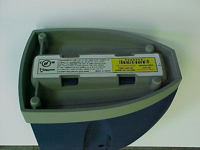
ArialPhone Corporation FCC ID#: PHIAP100BS Photo 1 Exterior View of ArialPhone Base Station ArialPhone Corporation FCC ID#: PHIAP100BS Photo 2 Exterior View of ArialPhone Base Station Showing the FCC ID Label attached to the Base of the Base Station

Operational Description

L.S. RESEARCH Inc. HIGH TECHNOLOGY ELECTRONIC CONSULTANTS File:Base Station Theory of Op CONFIDENTIAL Page 1 of 1 March 9, 2001 Arial Base Station Theory of Operation The Arial Earset is a direct sequence spread spectrum (DSSS) wireless audio device based on the Conexant Hummingbird chipset. A time division duplex (TDD) scheme is used to give full duplex audio operation while only occupying a single RF channel. It can operate on any one of 20 preassigned channels in the 902 to 928 MHz ISM band. The user has no control over channel assignment. When a link is established the chipset monitors signal quality and dynamically changes channels to avoid interference. Conducted output power is a maximum of +21dBm. DAACODEC USB Interface Micro Controller Computer Audio In Audio Out PCM Control Bus USB Radio Hummingbird Chipset CODEC PCM Phone Line Caller ID Tip Ring Audio Switch Network Switch Control Figure 1. System block diagram Matching Network T/R Switch Bandpass Filter Lowpass Filter Receive Amplifier Transmit Amplifier Baseband Demodulator Baseband Modulator Baseband Processor Audio CODEC Audio Input Audio Output USB Interface RF105 ChipHummingbird ASIC RF106 Chip Figure 2. Radio block diagram

RF Exposure Info

Page 3 of 3 _____________________________________________________________________________ W66 N220 Commerce Court, Cedarburg, Wisconsin 53012 • 262-375-4400 • FAX 262-375-4248 Email: [email protected] http://www.lsr.com/ 1. We need an MPE calculation to prove that the device is safe at 20cm. The power density associated with a particular electric field intensity is: ( ) 2 2 222 ; 377120 m Watts Ohms m V EEE W==== πη The power density at a distance from an isotropic radiating source is: () 22 ; 4m Watts r W rW t π = If identical isotropic transmitting and receiving antennas are used, the received power at a distance from an isotropic radiating source is: ()() PrWrA WA r P r Watts tt =⋅= ⋅ = 44 22 ππ ; Solving for transmit power and expressing the received power in terms of received electric field intensity: () PPrr E rWatts t ==4 120 4 2 2 2 π π π; Since the electric field intensity is specified at a 3 meter distance and we are interested in the effective transmit power in dBm: r = 3 meters P (W)=P(mW) x 1000 E(V) = E(uV) x 10 -6 Page 4 of 4 _____________________________________________________________________________ W66 N220 Commerce Court, Cedarburg, Wisconsin 53012 • 262-375-4400 • FAX 262-375-4248 Email: [email protected] http://www.lsr.com/ () ()()() P E EdBm t =⋅         =++−10 30 31000202031010001030 10 2 2 10101010 logloglogloglog () () ()()() PEdBm tV =−++− − 2020102031010001030 1010 6 101010 logloglogloglog μ () PEdBm tV =−++−20120954301477 10 log.. μ () PEdBm tV =−209523 10 log. μ The conversion between effective radiated power and the magnitude of the electric field intensity at a 3 meter distance from the transmitting source are related by: dBmEP VdBt 23.95−= μ The reported intentional emissions of the base-station are as follows. channel 1 114.5 dBuV/m channel 9 114.1 dBuV/m channel 13 113.5 dBuV/m The worst case is channel 1. A graph of the actual test indication is presented below for reference: The effective radiated power for this worst case emission is: Page 5 of 5 _____________________________________________________________________________ W66 N220 Commerce Court, Cedarburg, Wisconsin 53012 • 262-375-4400 • FAX 262-375-4248 Email: [email protected] http://www.lsr.com/ dBm m VdB P mr t 27.1923.955.114 3 =−= = μ The expected power density at a 20 centimeter distance is: () () 22 2 3 10 27.19 2 2.168 10204 10 10 4m mW m W mW r W rW dBm t = × ⋅ == − −         π π Re-normalizing this power density on a per square centimeter basis: () 22 24 2 82.16 10 2.168 cm W cm m m mW rW μ =⋅= − The limit for Maximum Permissible Exposure (MPE) given in Table 1 of §1.1310 is given as () 222 max 7.618 1500 928 1500 )( cm W mW cmMHz MHz mW cmMHz MHzf rW μ = − = − = The base-station uses a Time-Division-Duplex Protocol where the transmitter has a constant duty factor of 50%. Section 2.1091 allows for time averaging of the transmit power for the purposes of the MPE calculations. This fact would reduce the average power to one-half the constantly transmitting value: () 2 41.8 cm W rW μ = Since: ()() 2 max 2 7.61841.8 cm W rW cm W rW μμ =<= Therefore, the device in question meets the MPE requirmement. 5. The output power needs to be measured with a bandwidth which captures the full power of the signal. A power meter is the preferred

Schematics

Arial Base Station.sch-1 - Tue Feb 13 07:17:52 2001 Arial Base Station.sch-2 - Tue Feb 13 07:17:53 2001

Test Report

. . . . . . . . . . . . . . . . . . . L. S. Compliance, Inc. Compliance Testing of: Arial Basestation AP100BS Prepared for: ArialPhone L.L.C. Gerald L Hansberger Test Report Number: 301165 (rev 2) Date(s) of Testing: January 31, February 12, March 8, 19, 2001 All results of this report relate only to the items that were tested.All results of this report relate only to the items that were tested. This report may not be reproduced, except in full, without written approval ofThis report may not be reproduced, except in full, without written approval of L. S. Compliance, Inc. L. S. Compliance, Inc. L. S. Compliance, Inc. W66 N220 Commerce Court Cedarburg, Wisconsin 53012 Phone: 414 - 375 - 4400 Fax: 414 - 375 - 4248 L. S. COMPLIANCE, Inc. FCC ID : PHIAP100BSFCC ID : PHIAP100BS LSC-Arial 301165 Page 1 of 26 INDEXINDEX SectionSection DescriptionDescription Page #Page # Cover Page Index 1 Description of Measurement Facilities 2 Accreditation certificate; A2LA 3 Signature Page 4 2.3 Summary of Test Report 5 2.4 Introduction 5 2.5 Purpose 6 2.6 Conducted Emissions 6 2.7 Radiated Emission Test Setup 7 2.8 Radiated Emission Test Procedure 7 2.9 Test Equipment Utilized 8 2.10 Restricted Bands Affected 9 2.11 Photos taken of testing 10 2.12 Conclusions 12 2.13 Test Equipment List 13 Appendices A Sample Calculations: 14 i. Calculation of Radiated Emissions Limits 15 B Data Charts 16 C Graphs 20 L. S. COMPLIANCE, Inc. FCC ID : PHIAP100BSFCC ID : PHIAP100BS LSC-Arial 301165 Page 2 of 26 DESCRIPTION OF MEASUREMENT FACILITIES Site on File with the FCC ID Number: 31040/SIT 1300F2 Site on file with Industry canada: ID number IC 3088 “ The site referenced above has been found to comply with the test site criteria found in ANSI C63.4-1992 and 47CFR Section 2.948.” L. S. COMPLIANCE, Inc. FCC ID : PHIAP100BSFCC ID : PHIAP100BS LSC-Arial 301165 Page 3 of 26 L. S. COMPLIANCE, Inc. FCC ID : PHIAP100BSFCC ID : PHIAP100BS LSC-Arial 301165 Page 4 of 26 SIGNATURE PAGE Testing By: March 21 2001 Thomas T. Lee Date Testing By: March 21 2001 Kenneth L. Boston PE Date Prepared by: Approved by March 21 2001 Kenneth L. Boston, EMC Lab Manager Date PE #31926 Registered Professional Engineer (State of Wisconsin) L. S. COMPLIANCE, Inc. FCC ID : PHIAP100BSFCC ID : PHIAP100BS LSC-Arial 301165 Page 5 of 26 2.3 SUMMARY OF TEST REPORT MANUFACTURER: ArialPhone L.L.C. MODEL: AP100BS SERIAL: engineering sample DESCRIPTION: Voice based wireless base FREQUENCY RANGE: 902-928 MHz The Arial AP100BS was found to meetmeet the radiated emission specification of Title 47 CFR FCC, Part 15, subpart C., and also Industry Canada RSS-210 section 6.2.2 (o) for an intentional radiator The Arial AP100BS was also found to meetmeet the radiated emission specification of Title 47 CFR, FCC Part 15, subpart B (I.C. RS-210)for emissions with regards to the receiver and digital sections of the product. This product is a composite device, with the digital sections subject to verification. Therefore this technical report will primary contain data that is pertinent to the certification of the transmitter section of the product. 2.4 INTRODUCTION On January 31, February 12, March 8,19, of 2001, a series of Radiated and Conducted Emissions tests were performed on a sample model of the AP100BS, a spread spectrum transceiver designed to be the base station in a hands free communication system. These tests were performed using the test procedures outlined in ANSI C63.4-1992 for intentional radiators, and in accordance with the requirements set forth in FCC Part 15.247 for a direct sequence spread spectrum transmitter. Tests were also performed as outlined in ANSI C63.4-1992 for non-intentional radiators, in order to verify compliance with the limits set forth in part 15.109 for and to allow verification of emissions for the digital section of the product. These tests were performed by Thomas T. Lee and Kenneth L. Boston PE, of L. S. Compliance, Inc. L. S. COMPLIANCE, Inc. FCC ID : PHIAP100BSFCC ID : PHIAP100BS LSC-Arial 301165 Page 6 of 26 2.5 PURPOSE The above mentioned tests were performed in order to determine the compliance of the AP100BS product with limits contained in various provisions of Title 47 CFR, FCC Part 15, including: 15.109 15.209 15.247c 15.205 15.247a2 15.247d 15.207 15.247b 15.247e (Industry Canada RSS-210, 6.2.2.(o) ) Various of these tests, including the conducted RF out the antenna port and the jamming margin test are contained in an additional test report that is attached to this report. All radiated emissions tests were performed to measure the emissions in the frequency bands described by the above sections, and to determine whether said emissions are below the limits established by the above sections. These tests were performed in accordance with the procedure described in the American National Standard for methods of measurement of Radio-Noise Emissions from Low-Voltage Electrical and Electronic Equipment in the Range of 9 kHz to 40 GHz (ANSI C63.4-1992). Another document used as reference for the EMI receiver specification was the International Special Committee on Radio Interference (CISPR) number 16-1 (1993). 2.6 Conducted (AC LINE) Test Setup and measurements The Conducted Emission tests were performed within an 8 by 10 foot shielded room located at L. S. Compliance, Inc. in Cedarburg, WI. The test item was placed on a non-conductive rubber cart, with a height of 80 cm above the reference ground plane. The test object was spaced 40 cm from the rear wall of the shielded room and further than 80 cm from adjacent walls, and the test object power supply was plugged into a 50 (ohm) 50/250μH Line Impedance Stabilization Network (LISN). The test area and set- up are in accordance with ANSI C63.4-1992, sections 5, 6, and 7. The AC power supply to the LISN was fed into the shielded room via an appropriate broadband EMI filter. The test sample was set to operate on the middle channel in continuous transmit during the measurements, and operation…

Text truncated - open the document above for the full version.

Test Report

Page 1 of 1 _____________________________________________________________________________ W66 N220 Commerce Court, Cedarburg, Wisconsin 53012 • 262-375-4400 • FAX 262-375-4248 Email: [email protected] http://www.lsr.com/ FCC ID: PHIAP100BS ADDENDUM TO CONDUCTED MEASUREMENT REPORT The following email response from the Technical Certification Body with regard to the initial FCC filing associated with the FCC ID number PHIAP100BS is presented for reference. This addendum addresses and resolves the action items presented in the correspondence that are related only to theory of operation, conducted measurements and RF Exposure. All other issues are to be addressed in a separate addendum to the radiated emissions report. The issues addressed in this addendum are underlined. ----- Original Message ----- From: Certification Manager To: Jim Blaha Sent: Thursday, March 29, 2001 12:38 PM Subject: FCC ID: PHIAP100BS Hi Jim, We have conducted our review and have found the following issues: 1. We need an MPE calculation to prove that the device is safe at 20cm. 2. We need an RF exposure warning in the manual such as: ""IMPORTANT NOTE: To comply with FCC RF exposure compliance requirements, the following antenna installation and device operating configurations must be satisfied - The antenna(s) used for this transmitter must be installed to provide a separation distance of at least 20 cm from all persons and must not be co-located or operating in conjunction with any other antenna or transmitter." 3. For information only: We note that you did not think that RF Exposure concerns were an issue for this device. This is not the case. Please see attached FCC RF Exposure Procedure to determine when MPE calculations and warnings are required. For example this was a section F device (page 6). The Specific Procedures (SP) referenced are on page 13. 4. In table 18 of the test report only one type of detector data is shown. >From the text we conclude that it is average data. We need to confirm that the device complies with the peak limit of 15.35(b). This peak limit is 20dB above the average limit. Usually both average and peak data are reported to document compliance with both limits (alternatively, peak data which complies with the average limits is also acceptable). Please provide data to document compliance with the peak and average limits. Page 2 of 2 _____________________________________________________________________________ W66 N220 Commerce Court, Cedarburg, Wisconsin 53012 • 262-375-4400 • FAX 262-375-4248 Email: [email protected] http://www.lsr.com/ 5. The output power needs to be measured with a bandwidth which captures the full power of the signal. A power meter is the preferred measurement instrument. On page 11 of the test report the conducted power output measurements were made with a RBW of 100KHz. In the FCC procedure a RBW of greater than the 6dB bandwidth must be used. The 6dB bandwidth is about 1.5MHz. Please provide conducted power output data acquired using a bandwidth greater than 1.55MHz. 6. Please provide information on the length and shielding type of the two data cables attached to the product during radiated and conducted emissions. If shielded cables were used, then the manual must have a statement added instructing the user to utilize shielded cables on those ports so provisioned. 7. Please provide data responsive to the FCC 15.31 (e) requirements. 8. We need a better description of the spreading process to complete the evaluation of compliance with 15.247(e). Please discuss the available chip/symbol rate(s) and tell us the spreading rate and the data rate. If the spreading rate/data rate is less than 11:1, please provide a discussion of the theoretical processing gain of the system. 9. To comply with 2.925(a)(1) the FCC ID on the label must on a single line. Please supply a revised label exhibit. We have noted the label does include a Part 68 ID. How have you handled the Part 68 certification? 10. Please supply details of the label material so we confirm compliance with 2.925(d). Best regards Barry C. Quinlan Certification & Telecom Manager ------------------------------------------------------------------------------- Curtis-Straus LLC Voice: 978.486.8880 x270 527 Great Road Fax: 978.486.8828 Littleton, MA 01460 http://www.curtis-straus.com -------------------------------------------------------------------------------- Action Item resolution: Page 3 of 3 _____________________________________________________________________________ W66 N220 Commerce Court, Cedarburg, Wisconsin 53012 • 262-375-4400 • FAX 262-375-4248 Email: [email protected] http://www.lsr.com/ 1. We need an MPE calculation to prove that the device is safe at 20cm. The power density associated with a particular electric field intensity is: ( ) 2 2 222 ; 377120 m Watts Ohms m V EEE W==== πη The power density at a distance from an isotropic radiating source is: () 22 ; 4m Watts r W rW t π = If identical isotropic transmitting and receiving antennas are used, the received power at a distance from an isotropic radiating source is: ()() PrWrA WA r P r Watts tt =⋅= ⋅ = 44 22 ππ ; Solving for transmit power and expressing the received power in terms of received electric field intensity: () PPrr E rWatts t ==4 120 4 2 2 2 π π π; Since the electric field intensity is specified at a 3 meter distance and we are interested in the effective transmit power in dBm: r = 3 meters P (W)=P(mW) x 1000 E(V) = E(uV) x 10 -6 Page 4 of 4 _____________________________________________________________________________ W66 N220 Commerce Court, Cedarburg, Wisconsin 53012 • 262-375-4400 • FAX 262-375-4248 Email: [email protected] http://www.lsr.com/ () ()()() P E EdBm t =⋅         =++−10 30 31000202031010001030 10 2 2 10101010 logloglogloglog () () ()()() PEdBm tV =−++− − 2020102031010001030 1010 6 101010 logloglogloglog μ () PEdBm tV =−++−20120954301477 10 log.. μ () PEdBm tV =−209523 10 log. μ The conversion between effective radiated power and the magnitude…

Text truncated - open the document above for the full version.

Test Report

.......... . . . . . . . . . . LS Research Inc. Airal Phone Base Station FCC ID: PHIAP100BS Part 15.247 Type Acceptance, Conducted Measurements prepared for Arial Phone Revision 1.0 L.S. RESEARCH Inc. 2 of 51 HIGH TECHNOLOGY ELECTRONIC CONSULTANTS FCC ID: PHIAP100BS WE HAVE DESIGNS ON THE FUTURE W66 N220 Commerce Court, Cedarburg, Wisconsin 53012 • 414-375-4400 • FAX 414-375-4248 Email: [email protected] www.lsr.com Table of Contents I. Project Information ............................................................................................................................................... 3 II. FCC Conducted Tests ...................................................................................................................................... 5 A. Part 15.247 .................................................................................................................................................... 5 1. 15.247 (a) (2) Emission 6 dB Bandwidth...................................................................................................... 5 2. 15.247 (b) (1) Output Power ....................................................................................................................... 10 3. 15.247 (b) (3) Effective Radiated Power..................................................................................................... 14 4. 15.247 (c) Spurious Modulation Products................................................................................................... 14 5. 15.247 (d) Power Spectral Density ............................................................................................................. 28 6. 15.247 (e) Processing Gain ......................................................................................................................... 33 III. Critical Equipment List ................................................................................................................................... 50 IV. Equipment Uncertainties ................................................................................................................................. 50 V. Bit Error Ratio Test Software ......................................................................................................................... 51 L.S. RESEARCH Inc. 3 of 51 HIGH TECHNOLOGY ELECTRONIC CONSULTANTS FCC ID: PHIAP100BS WE HAVE DESIGNS ON THE FUTURE W66 N220 Commerce Court, Cedarburg, Wisconsin 53012 • 414-375-4400 • FAX 414-375-4248 Email: [email protected] www.lsr.com Airal Phone Base Station I. Project Information Project: Airal PhoneBase Station Arial Systems Contact: Company: Arial Systems Corporation Full Name: Marc Cygnus Job Title: Senior Programmer Analyst 3 Hawthorn Parkway Vernon Hills, IL 60061 Bus: (847)-573-9925 ext. 228 Bus Fax: (847) 573-9926 E-mail: [email protected] LS Research Contact: Bill Steinike, Operations Manager Brian Petted, Vice President of Engineering Voice: 262-375-4400 Fax: 262-375-4248 Email: [email protected] Report Date: 3/20/01 Revision: 1.0 Proposal #: Proposal File: Arial Phone Job Number: L.S. RESEARCH Inc. 4 of 51 HIGH TECHNOLOGY ELECTRONIC CONSULTANTS FCC ID: PHIAP100BS WE HAVE DESIGNS ON THE FUTURE W66 N220 Commerce Court, Cedarburg, Wisconsin 53012 • 414-375-4400 • FAX 414-375-4248 Email: [email protected] www.lsr.com Signatures: Technical Approval L.S. RESEARCH Inc. 5 of 51 HIGH TECHNOLOGY ELECTRONIC CONSULTANTS FCC ID: PHIAP100BS WE HAVE DESIGNS ON THE FUTURE W66 N220 Commerce Court, Cedarburg, Wisconsin 53012 • 414-375-4400 • FAX 414-375-4248 Email: [email protected] www.lsr.com II. FCC Conducted Tests A. Part 15.247 1. 15.247 (a) (2) Emission 6 dB Bandwidth a) Test Requirement The 6 dB bandwidth of the Equipment emission must be greater than 500 kHz. kHzB dB 500 6 > − b) Test Configuration The test configuration is presented below: HP E4404B Spectrum Analyzer #CC00221C Transmitter Under Test RG-316 Launch / SMA SMA / N L.S. RESEARCH Inc. 6 of 51 HIGH TECHNOLOGY ELECTRONIC CONSULTANTS FCC ID: PHIAP100BS WE HAVE DESIGNS ON THE FUTURE W66 N220 Commerce Court, Cedarburg, Wisconsin 53012 • 414-375-4400 • FAX 414-375-4248 Email: [email protected] www.lsr.com c) Test Conditions: Equipment Under Test The equipment under test is tunable and is set to 3 different channels, one representing the minimum tunable frequency, one representing a midband frequency and one representing the maximum tunable frequency. The frequencies and their hexadecimal channel designators are presented below for reference. Channel 1: 904.8 MHz Channel 9: 914.5 MHz Channel 13: 925.8 MHz Test indications under these three frequency conditions are presented. The output power is fixed to its maximum , worst-case value. d) Test Conditions: Instrumentation Conditions The readings indicated on the spectrum analyzer are a result of a marker search function which determines the 6 dB bandwidth of the indicated spectrum. The spectrum analyzer display indicates its conditions as follows: Center: Center Frequency Span: Frequency Span Res BW: Resolution Bandwidth VBW: Video (averaging) Bandwidth Sweep: Frequency Sweep time over indicated frequency Span. L.S. RESEARCH Inc. 7 of 51 HIGH TECHNOLOGY ELECTRONIC CONSULTANTS FCC ID: PHIAP100BS WE HAVE DESIGNS ON THE FUTURE W66 N220 Commerce Court, Cedarburg, Wisconsin 53012 • 414-375-4400 • FAX 414-375-4248 Email: [email protected] www.lsr.com e) Test Indications Test Condition: Channel 1: 904.80 MHz Test Limit: 500 kHz, minimum. Test Indication: 1.546 MHz Test Outcome: 1.546 MHz > 500 kHz → PASS L.S. RESEARCH Inc. 8 of 51 HIGH TECHNOLOGY ELECTRONIC CONSULTANTS FCC ID: PHIAP100BS WE HAVE DESIGNS ON THE FUTURE W66 N220 Commerce Court, Cedarburg, Wisconsin 53012 • 414-375-4400 • FAX 414-375-4248 Email: [email protected] www.lsr.com Test Condition: Channel 9: 914.5 MHz Test Limit: 500 kHz, minimum. Test Indication: 1.471 MHz Test Outcome: 1.471 MHz > 500 kHz → PASS L.S. RESEARCH Inc. 9 of 51 H…

Text truncated - open the document above for the full version.

Contact Information

Applicant

Jerry Hansberger(VP Operations and General Manager)
[email protected]847-573-9925Fax: 847-573-9926

Test Firm

LS Research, LLCRyan Urness
[email protected]262-375-4400Fax: 262-375-4248

Technical Specifications

#Rule PartsFrequency RangePower Output
115C902 MHz - 928 MHz48.00 mW
Grant Notes
Grant Conditions � The antenna used for this transmitter must be installed to provide a separation distance of at least 20 cm from all persons and must not be co-located or operating in conjunction with any other antenna or transmitter. End-users and installers must be provided with antenna installation instructions and transmitter operating conditions for satisfying RF exposure compliance.

Other Applications from ArialPhone L.L.C.
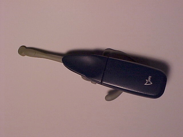
Voice-based Wireless Earset - FCC ID PHIAP100 - ArialPhone L.L.C.
PHIAP100

Voice-based Wireless Earset

Jun 24, 2001

Equipment Class

DSS - Part 15 Spread Spectrum Transmitter