PHNTL03RFPatient Monitoring Transmitter
Global DME,Inc.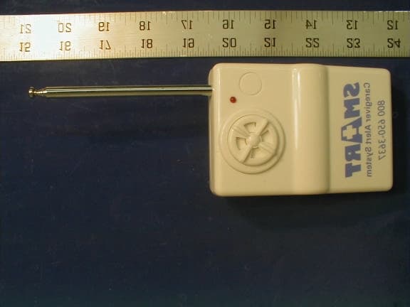
Click to zoom
Application Details
- Equipment Class
- DXX - Part 15 Low Power Communication Device Transmitter
- Date of Grant
- Mar 22, 2001
- Application Purpose
- Original Equipment
- Date of Application
- Mar 05, 2001
- Equipment Note
- Patient Monitoring Transmitter
- Frequency Range
- 26.96000000 - 27.28000000
- Company
- Global DME,Inc.
- Country
- United States
Documents & Files
Document Text
Text extracted from the exhibit documents filed with the FCC. Open a document above to read the original.
Operational Description
Technical Manual Specifications: a. Input: A: 9V Battery B: 9V DC b. Frequency: 27.184MHz(26.96-27.28MHz) c. Code Setting: 31441(3) d. Remote Distance: 25m e. Low Battery Indicator: LED will light continuously when battery voltage below 5.5V
Test Report
Note: This report may not be duplicated without prior written consent of Bay Area Compliance Laboratory Corporation. This report must not be used by the client to claim product endorsement by NVLAP or any agency of the U.S. Government. FCC ID PER PART 15.227 EMI MEASUREMENT AND TEST REPORT For Global DME, Inc. 619 Martin Ave. #6, Rohnert Park, CA 94928 FCC ID: PHNTL03RF March 1, 2001 This Report Concerns: Original Report Equipment Type: Caregiver Alert System Test Engineer: Jeff Lee Test Date: February 15, 2001 Reviewed By: John Y. Chan – Engineering Manager Prepared By: Bay Area Compliance Laboratory Corporation 230 Commercial Street, Suite 2 Sunnyvale, CA 94086 Tel: (408) 732-9162 Fax: (408) 732 9164 Global DME, Inc. FCC ID: PHNTL03RF Report # Test Report FCC Part 15.227 Test Report Page 2 of 14 TABLE OF CONTENTS 1 - GENERAL INFORMATION.................................................................................................................................................3 1.1 PRODUCT DESCRIPTION FOR EQUIPMENT UNDER TEST (EUT)........................................................................................3 1.2 OBJECTIVE................................................................................................................................................................................3 1.3 RELATED SUBMITTAL(S)/GRANT(S).....................................................................................................................................3 1.4 TEST METHODOLOGY..............................................................................................................................................................3 1.5 TEST FACILITY.........................................................................................................................................................................3 1.6 TEST EQUIPMENT LIST............................................................................................................................................................4 1.7 EQUIPMENT UNDER TEST (EUT)...........................................................................................................................................4 2 - SYSTEM TEST CONFIGURATION..................................................................................................................................5 2.1 JUSTIFICATION..........................................................................................................................................................................5 2.2 BLOCK DIAGRAM.....................................................................................................................................................................5 2.3 TEST SETUP BLOCK DIAGRAM...............................................................................................................................................6 2.4 EQUIPMENT MODIFICATIONS.................................................................................................................................................7 3 - CONDUCTED EMISSIONS TEST DATA........................................................................................................................8 4 - RADIATED EMISSION DATA............................................................................................................................................9 4.1 EUT SETUP...............................................................................................................................................................................9 4.2 SPECTRUM ANALYZER SETUP................................................................................................................................................9 4.3 TEST PROCEDURE....................................................................................................................................................................9 4.4 CORRECTED AMPLITUDE & MARGIN CALCULATION.........................................................................................................9 4.5 SUMMARY OF TEST RESULTS...............................................................................................................................................10 4.6 RADIATED EMISSIONS TEST RESULT DATA.......................................................................................................................10 5 – MEASUREMENT OF EMISSIONS WITHIN BAND EDGES.................................................................................11 APPENDIX A – AGENCY AUTHORIZATION LETTER...............................................................................................13 Global DME, Inc. FCC ID: PHNTL03RF Report # Test Report FCC Part 15.227 Test Report Page 3 of 14 1 - GENERAL INFORMATION 1.1 Product Description for Equipment Under Test (EUT) The Global DME, Inc.’s model TL-03RFor the "EUT" as referred to in this report is a 26.96-27.28MHz RF transmitter that is a wireless remote Caregiver Alert System. The EUT measures 4.0” L x 2.75” W x 1.75” H. 1.2 Objective This certification report is prepared on behalf of Global DME, Inc. in accordance with Part 2, Subpart J, and Part 15, Subparts A, B, and C of the Federal Communication Commissions rules. The objective of the manufacturer is to demonstrate compliance with FCC rules, Part 15, sec 227 for field strength requirement. 1.3 Related Submittal(s)/Grant(s) No Related Submittals 1.4 Test Methodology All measurements contained in this report were conducted with ANSI C63.4 –1992, American National Standard for Methods of Measurement of Radio-Noise Emissions from Low-Voltage Electrical and Electronic Equipment in the range of 9 kHz to 40 GHz. All radiated and conducted emissions measurement was performed at Bay Area Compliance Laboratory, Corp. The radiated testing was performed at an antenna-to-EUT distance of 3 meters. 1.5 Test Facility The Open Area Test site used by Bay Are…
Text truncated - open the document above for the full version.
Contact Information
Applicant
Timothy Long(General Manager)
Technical Contact
Bay Area Compliance LaboratoryJohn Chan
[email protected](408)732-9162
230 Commercial St. Suite 2 · Sunnyvale, California · United States
Non-Technical Contact
Bay Area Compliance LaboratoryRita Cai
[email protected](408)732-9162
Test Firm
Bay Area Compliance LaboratoryJohn Chan
Technical Specifications
| # | Rule Parts | Frequency Range | Power Output |
|---|---|---|---|
| 1 | 15C | 26.96 MHz - 27.28 MHz | - |
Other Applications from Global DME,Inc.
PHNTXW01
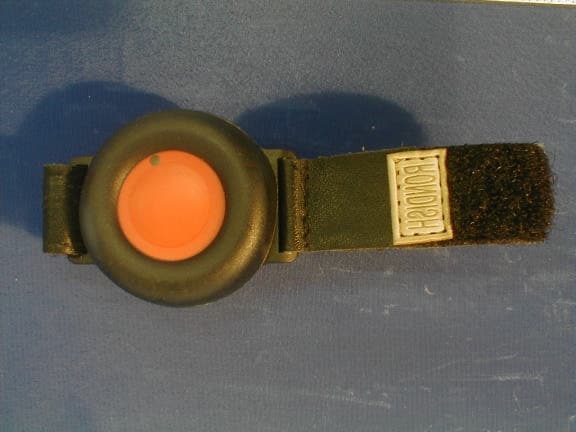
Apr 22, 2001Wrist Band w/Nurse Call
Equipment Class
DXX - Part 15 Low Power Communication Device Transmitter